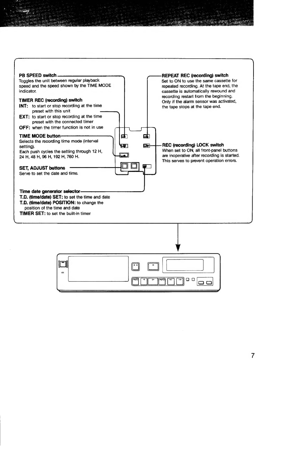
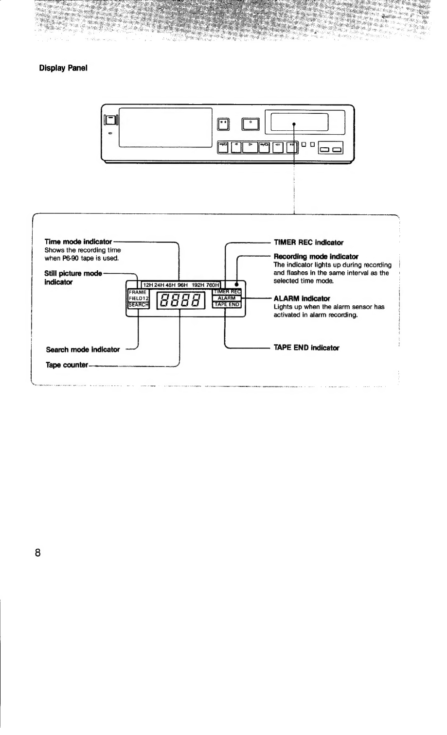
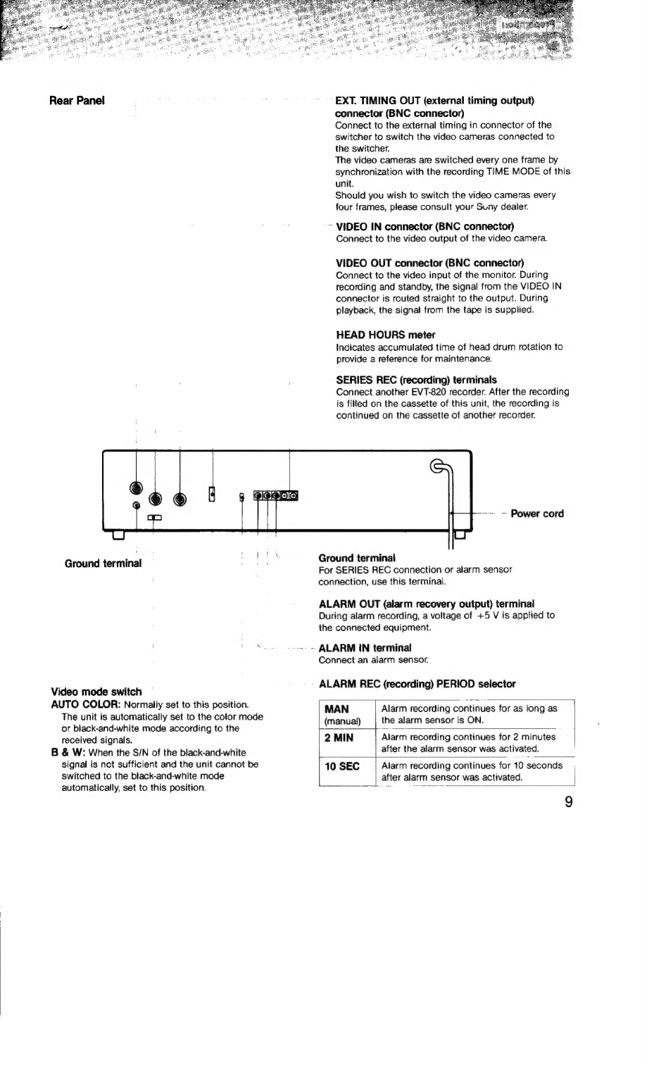
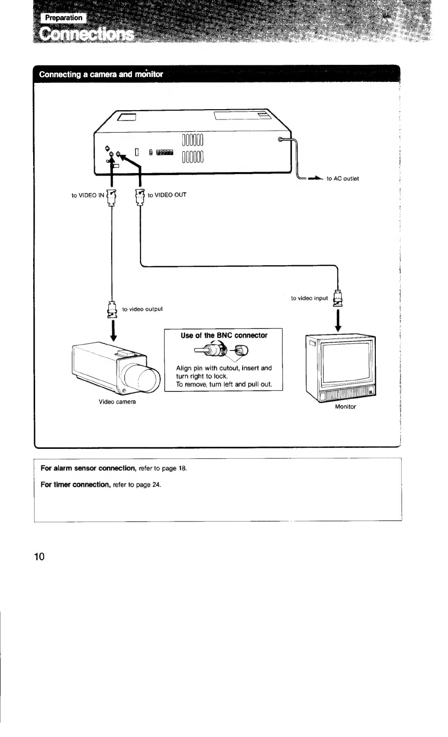
Sony WatchCorder EVT-820 User manual
Other Sony Measuring Instrument manuals


Sony
Sony SVT-RA40 User manual

Sony
Sony MZ-NH600 User manual

Sony
Sony DK110NLR5 User manual
 User manual")
Sony
Sony RDR-VX500 (RDRVX500) User manual

Sony
Sony NEX-FS700 User manual

Sony
Sony DK812FR User manual

Sony
Sony PMW50 User manual

Sony
Sony DCR-PC115 User manual

Sony
Sony MZ-N920 User manual

Sony
Sony MAV-555A User manual