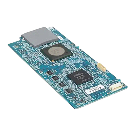
Sony HKPF-9000 User manual

OPERATION MANUAL
1st Edition
Serial No. 10001 and Higher
MULTI FORMAT CONVERTER BOARD
HKPF-9000
警告
電気製品は、安全のための注意事項を守らないと、火災
や人身事故になることがあります。
このオペレーションマニュアルには、事故を防ぐための重要な注意事項と製
品の取り扱いかたを示してあります。このオペレーションマニュアルをよく
お読みのうえ、製品を安全にお使いください。お読みになったあとは、いつ
でも見られるところに必ず保管してください。
本機をあやまって装着すると、火災・感電やその他の事故により、けがをし
たり周辺の物品に損害を与えたりすることがあります。危険を避けるため、
装着はサービストレーニングを受けた技術者にご依頼ください。
本機を装着する技術者へ
装着のしかたは、デジタルビデオインターフェースユニットに付属のマニュ
アルをご覧ください。
Japanese/English/French/German

ソニー製品は安全に十分に配慮して設計されています。しかし、電気製品は、
安全のための注意事項を守らないと、火災や感電などにより死亡や大けがな
ど人身事故につながることがあり、危険です。
事故を防ぐために次のことを必ずお守りください。
安全のための注意事項を守る
2(JP)ページの注意事項をよくお読みください。
この「安全のために」は、本製品の接続先であるデジタルビデオインター
フェースユニットまたはその関連機器に関する安全上の注意事項を記載して
います。
オプションユニットの装着について
危険を避けるために、オプションユニットの装着はサービストレーニングを
受けた技術者、もしくはソニーのサービス担当者または営業担当者にご依頼
ください。
定期点検を実施する
長期間安全に使用していただくために、定期点検を実施することをおすすめ
します。点検の内容や費用については、ソニーのサービス担当者または営業
担当者にご相談ください。
故障したら使用を中止する
ソニーのサービス担当者、または営業担当者にご連絡ください。
万一、異常が起きたら
警告表示の意味
このオペレーションマニュアル
および製品では、次のような表
示をしています。表示の内容を
よく理解してから本文をお読み
ください。
警告
この表示の注意事項を守らない
と、火災や感電などにより死亡
や大けがなど人身事故につなが
ることがあります。
注意を促す記号
行為を禁止する記号
禁止
1電源を切る。
2電源コードや接続コードを抜く。
3ソニーのサービス担当者、または営業担当者に
修理を依頼する。
すぐに電源を切り、消火する。
異常な音、に
おい、煙が出
たら
/
炎が出たら /
日本語 安全のために
火災 感電

1 (JP)
目次
警告....................................................................................................................... 2(JP)
概要 ........................................................................................................................ 3(JP)
HKPF-9000の特長.............................................................................................3(JP)
各部の名称と働き .................................................................................................... 4(JP)
フロントパネル ..................................................................................................... 4(JP)
コネクターパネル ................................................................................................ 5(JP)
仕様 ........................................................................................................................ 7(JP)
日
本
語

2(JP)
警告
禁止
油煙、湯気、湿気、ほこりの多い場所では設置•使用しない
上記のような場所で設置・使用すると、火災や感電の原因となります。
下記の注意を守らないと、
火災や感電により死亡や大けがにつながることがあります。
感電火災
警告

3 (JP)
概要
注意
マルチフォーマットコンバーター基板HKPF-9000は、HDSDI
信号とSDSDI(D1SDI)信号を相互に変換する基板です。
HKPF-9000は、デジタルビデオインターフェースユニットPFV-
HD50A/HD300に組み込んで使用します。動作に必要な電源
は、インターフェースユニットから供給されます。
HKPF-9000の構造および電源電圧は、デジタルビデオインター
フェースユニットPFV-HD50A/HD300用に企画された他の
HKPFシリーズとすべて共通です。これらの基板は、各イン
ターフェースユニットに任意の組み合わせで装着して同時運用
することができ、柔軟なシステム構成が可能になります。
ご注意
デジタルインターフェースユニットにHKPF-9000だけを組み込
んで使用する場合、組み込み可能数は下記のとおりです。
PFV-HD50A:最大1セット
PFV-HD300:最大4セット
基板上のスイッチの設定については、サービストレーニングを
受けた技術者にご依頼ください。
HKPF-9000は以下のものから構成されます。
基板(2)
コネクターパネル(2)
オペレーションマニュアル(1)
インストレーションマニュアル(1)
スロット番号ラベル(1組)
HKPF-9000の特長
HD SDI信号とSD SDI信号の相互変換
HDSDI信号とSDSDI信号を相互に変換することができます。
◆ 変換フォーマットとスイッチ設定については、同梱のインストレーションマ
ニュアルをご覧ください。
エンベデッドオーディオ信号の乗せ換え
入力SDI信号のエンベデッドオーディオ信号を、出力SDI信号に
エンベデッドして出力することができます。
タイムコード信号の乗せ換え
入力SDI信号のタイムコード信号を、出力SDI信号にエンベデッ
ドして出力することができます。
3種類のアスペクト比
変換時、出力信号のアスペクト比を3種類のモードから選択す
ることが出来ます。
SQUEEZE
(スクイーズ):HD,SD変換時、HD画面(アスペ
クト比16:9)をそのままSD 画面(アスペクト比4:3)のフル画
面に変換します。SD,HD変換時は、SD画面(アスペクト比
4:3)をそのままHD画面(アスペクト比16:9)のフル画面に変
換します。
LETTER BOX
(レターボックス):HD,SD変換時、HD画面
のアスペクト比16:9を維持したまま変換します。SD,HD変
換時は、SD画面の上下1/4をカットし、16:9のアスペクト比で
出力します。
EDGE CROP
(エッジクロップ):HD,SD変換時、HD画面
の左右 1/4をカットし、4:3のアスペクト比で出力します。
SD,HD変換時は、SD画面のアスペクト比4:3を維持したま
ま変換します。
外部同期信号に同期
出力SDI信号を外部同期信号(1125または525/625SYNC)に同期
させて出力することができます。
リモートコントロール機能
別売りのHDデジタルビデオコントローラーHKDV-900を接続し
て、ビデオゲイン、イメージエンハンサーなどの調整をリモー
トコントロールすることができます。
ステータスアウト機能
基板の動作状態をモニターするためのステータスアウト機能に
対応しています。

4(JP)
各部の名称と働き
各部の名称と働き
フロントパネル
POWER
(+5V/−5V電源表示)ランプ
VIDEO EXIST
(ビデオ入力表示)ランプ
AUDIO EXIST
(オーディオ入力表示)ランプ
CRCC/EDH
(エラー表示)ランプ
INPUT FORMAT
(入力信号フォーマット番号表示)LED
INPUT SELECT
(入力信号選択)スイッチ
OPTPUT SELECT
(出力信号フォーマット選択)スイッチ
POWER
(+5V/−5V電源表示)ランプ
REF SELECT
(リファレンス信号選択スイッチ)
REMOTE/LOCAL
(リモートコントロール選択)スイッチ
ASPECT
(アスペクト比選択)スイッチ
SQ:SQueeze
LB:LetterBox
EC:EdgeCrop
DTL GAIN/CRISP/H/V RATIO
(ディテール調整)スイッチ
HKPF-9000
POWER
VIDEO
AUDIO
CRCC/EDH
HD
SD(Single)
SD(Dual)
INPUT SELECT
OUTPUT SELECT
INPUT FORMAT
DTL GAIN CRISP H/V RATIO
88
0
1
2
3
4
5
6
7
8
9
A
B
C
D
E
F
0
1
2
3
4
5
6
7
8
9
A
B
C
D
E
F
MFC-2
HKPF-9000
SQ
LB
EC
ASPECT
REF SELECT
OUTPUT SELECT
0
1
2
3
4
5
6
7
8
9
A
B
C
D
E
F
0
1
2
3
4
5
6
7
8
9
A
B
C
D
E
F
0
1
2
3
4
5
6
7
8
9
A
B
C
D
E
F
REMOTE
LOCAL
INPUT
POWER
EXT HD
EXT SD
MFC-1
◆ランプ、LED、スイッチの働きについて詳しくは、同梱のインストレーションマニュアルをご覧ください。

5 (JP)
SDI IN
MFC-1
1
2
1
2
VIDEO CONTROL
SDI OUT
ON
OFF
75Ω
1
2
HD OUT
HKPF-9000
HD IN
REF IN
MFC-2
HKPF-9000
REMOTE IN RS-232C ETHERNET
コネクターパネル
1D1 SDI IN端子
2D1 SDI OUT端子
3HD SDI IN端子
4HD SDI OUT端子
5REF IN端子
6LOOP OUT端子
775Ω終端切り換えスイッチ
8ETHERNET端子
9RS-232C端子
q;REMOTE IN端子
qaVIDEO CONTROL端子

6(JP)
各部の名称と働き
1D1 SDI IN端子(BNC型)
D1SDI信号を入力します。
2D1 SDI OUT端子(BNC型)
変換後のD1SDI信号を出力します。
3HD SDI IN端子(BNC型)
HDSDI信号を入力します。
4HD SDI OUT端子(BNC型)
変換後のHDSDI信号を出力します。
5REF IN(外部同期信号入力)端子(BNC型)
1125または525/625SYNC信号を入力します。
6LOOP OUT(外部同期信号出力)端子(BNC型)
REFIN端子に入力されたSYNC信号を出力します。
775Ω終端切り換えスイッチ
REFIN端子に入力されたSYNC信号の終端ON/OFFを切り換え
ます。
8ETHERNET(イーサネット)端子(モジュラージャック
8ピン)
別売りのアスペクト/カラープロセッサーHZPF-9005使用時、外
部パーソナルコンピューターと接続します。
9RS-232C端子(D-sub 9ピン)
メンテナンス時、外部機器とRS-232Cシリアルリモートコント
ロール信号の通信を行います。
q;REMOTE IN(リモートコントロール入力)端子
外部機器とRS-422Aシリアルリモートコントロール信号の通信
を行います。
qaVIDEO CONTROL(ビデオコントロール)端子
別売りのデジタルビデオコントローラーHKDV-900使用時、リ
モートコントロール信号を接続します。

7 (JP)
一般
電源 +4VDC:5.0A、−5VDC:3.0A
消費電力 約40W
動作温度 5℃〜40℃
保存温度 −20℃〜+55℃
湿度 10〜90%(結露のないこと)
外形寸法 基板:194×310mm(高さ/奥行)
コネクターパネル:218×98×25mm
(高さ/奥行/幅)
質量 基板:約1400g
コネクターパネル:約600g
入力
SDデジタル信号入力
SDIN1/2端子:BNC型(各1)
SDSDI信号(SMPTE-259M準拠、
270Mbps)
入力インピーダンス
75Ω、不平衡
入力端反射損失
15dB以上(5MHz〜270MHz)
入力ケーブル長
最大200m(5C-2V同軸ケーブル使用時)
HDデジタル信号入力
HDIN端子:BNC型(1)
HDSDI信号(BTAS-004B/005B/006B、
SMPTE-291M/292M/299M準拠)
入力インピーダンス
75Ω、不平衡
入力端反射損失
15dB以上(5MHz〜1.485GHz)
伝送損失 20dB以下(742.5MHzにて)
入力ケーブル長
最大100m(5C-FB同軸ケーブル使用時)
同期信号入力 REFIN端子:BNC型(1)
1125または525/625SYNC信号
入力インピーダンス
75Ω、不平衡
スイッチによるON/OFF切り換え可
ループスルー出力
LOOPOUT端子:BNC型(1)
出力
SDデジタル信号出力
SDOUT1/2端子:BNC型(各1)
SDSDI信号(SMPTE-259M準拠、
270Mbps)
出力信号振幅 800mVp-p±10%(75Ω負荷にて)
出力インピーダンス
75Ω、不平衡
出力端反射損失
15dB以上(5MHz〜270MHz)
ジッター タイミングジッター:740ps以下
アライメントジッター:740ps以下
HDデジタル信号出力
HDOUT1/2端子:BNC型(各1)
HDSDI信号(BTAS-004B/005B/006B、
SMPTE-291M/292M/299M準拠)
出力信号振幅 800mVp-p±10%(75Ω負荷にて)
出力インピーダンス
75Ω、不平衡
出力端反射損失
15dB以上(5MHz〜1.485GHz)
ジッター タイミングジッター:673ps以下
アライメントジッター:135ps以下
デジタル入出力システムディレイ
同梱のインストレーションマニュアルをご覧ください。
ステータスアウト
出力情報 ステータスメッセージ:4レベルから選択
リモートコントロール
対応リモートコントローラー
HDデジタルビデオコントローラーHKDV-
900
リモートコントロール信号入力
VIDEOCONTROL端子:D-sub9ピン、メ
ス
仕様および外観は、改良のため予告なく変更することがあります
が、ご了承ください。
仕様


1(GB)
English
Owner’s Record
The model and serial numbers are located on the top of the
unit. Record the serial number in the space provided below.
Refer to them whenever you call upon your Sony dealer
regarding this product.
Model No. HKPF-9000 Serial No. _______________
For the customers in U.S.A.
This equipment has been tested and found to comply with
the limits for a Class A digital device, pursuant to Part 15 of
the FCC Rules. These limits are designed to provide
reasonable protection against harmful interference when the
equipment is operated in a commercial environment. This
equipment generates, uses, and can radiate radio frequency
energy and, if not installed and used in accordance with the
instruction manual, may cause harmful interference to radio
communications. Operation of this equipment in a residential
area is likely to cause harmful interference in which case the
user will be required to correct the interference at his own
expense.
You are cautioned that any changes or modifications not
expressly approved in this manual could void your authority
to operate this equipment.
The shielded interface cable recommended in this manual
must be used with this equipment in order to comply with the
limits for a digital device pursuant to Subpart B of Part 15 of
FCC Rules.
This device complies with part 15 of the FCC Rules.
Operation is subject to the following two conditions: (1) This
device may not cause harmful interference, and (2) this
device must accept any interference received, including
interference that may cause undesired operation.
For the customers in Canada
This Class A digital apparatus complies with Canadian ICES-
003.
For the customers in Europe
This product with the CE marking complies with the EMC
Directive (89/336/EEC) issued by the Commission of the
European Community.
Compliance with this directive implies conformity to the
following European standards:
• EN55103-1: Electromagnetic Interference (Emission)
• EN55103-2: Electromagnetic Susceptibility (Immunity)
This product is intended for use in the following
Electromagnetic Environment: E4
(Controlled EMC environment, ex. TV studio).
English

Table of Contents
2(GB)
Table of Contents
Overview............................................................................................ 3(GB)
Features of the HKPF-9000......................................................... 3(GB)
Location and Function of Parts....................................................... 4(GB)
Front panels (circuit boards)........................................................ 4(GB)
Connector panels ......................................................................... 5(GB)
Specifications..................................................................................... 7(GB)

3(GB)
Overview
The HKPF-9000 Multi-format Converter Board
converts HD SDI signals to SD SDI (D1 SDI) signals,
and vice-versa.
The HKPF-9000 can be mounted in the PFV-HD50A/
HD300 Digital Video Interface Unit. Power to the
HKPF-9000 is supplied internally by the PFV-HD50A/
HD300.
This and other HKPF series circuit boards that are
planned for the PFV-HD50A/HD300 Digital Video
Interface Unit will share the same structure and power
requirements, thereby giving users the flexibility to use
various combinations of boards to suit their purposes.
Note
When only the HKPF-9000 is to be used in a digital
video interface unit, the maximum number of units that
can be mounted in each digital video interface unit is
as follows:
PFV-HD50A: 1 set
PFV-HD300: 4 sets
Consult Sony service personnel concerning the switch
settings on the HKPF-9000.
Each HKPF-9000 set comes with the following items:
•Circuit boards (2)
•Connector panels (2)
•Operation Manual (1)
•Installation Manual (1)
•Slot number stickers (1 set)
Features of the HKPF-9000
Bi-directional conversion between HD SDI
and SD SDI signals
The HKPF-9000 performs bi-directional conversions
between HD SDI signals and SD SDI signals.
For details concerning the signal format and the switch
settings for signal conversion, refer to the supplied
installaion manual.
Transfer of embedded audio signals to output
signal
Audio signals embedded in SDI input signals can be
added to and output with the SDI output signals.
Transfer of embedded time code signals to
output signal
Time code signals embedded in SDI input signals can
be added to and output with the SDI output signals.
Choice of three aspect ratios
Three aspect ratios can be selected for the converted
output signal.
SQUEEZE: During HD SDI-to-SD SDI conversion,
a full-size HD SDI picture (aspect ratio: 16:9) is
converted into a full-size SD SDI picture (aspect
ratio: 4:3). During SD SDI-to-HD SDI
conversion, a full-size SD SDI picture (aspect
ratio: 4:3) is converted into a full-size HD SDI
picture (aspect ratio: 16:9).
LETTER BOX: During HD SDI-to-SD SDI
conversion, an HD SDI picture is converted to an
SD SDI picture with the 16:9 aspect ratio intact.
During SD SDI-HD SDI conversion, the top-
quarter and bottom-quarter sections of the picture
are cut, and the picture is output with a 16:9 aspect
ratio.
EDGE CROP: During HD SDI-to-SD SDI
conversion, the right-quarter and left-quarter
sections of the picture are cut, and the picture is
output with a 4:3 aspect ratio. During SD SDI-to-
HD SDI conversion, the SD SDI picture is
converted to an HD SDI picture with the 4:3
aspect ratio intact.
Synchronization with an external sync signal
Converted signals can be output in synchronization
with an external 1125 or 525/625 sync signal.
Remote control capability
When the optional HKDV-900 HD Digital Video
Controller is connected, the video gain, image
enhancing, and other adjustments can be done
remotely.
Status information output
The HKPF-9000 supports the output of status
information output for monitoring the operation status
of the converter board.

Location and Function of Parts
4(GB)
For details on the function of the lamps, display, and switches, refer to the installation manual supplied with the unit.
Front panels (circuit boards)
Location and Function kf Parts
HKPF-9000
POWER
VIDEO
AUDIO
CRCC/EDH
HD
SD(Single)
SD(Dual)
INPUT SELECT
OUTPUT SELECT
INPUT FORMAT
DTL GAIN CRISP H/V RATIO
88
0
1
2
3
4
5
6
7
8
9
A
B
C
D
E
F
0
1
2
3
4
5
6
7
8
9
A
B
C
D
E
F
MFC-2
HKPF-9000
SQ
LB
EC
ASPECT
REF SELECT
OUTPUT SELECT
0
1
2
3
4
5
6
7
8
9
A
B
C
D
E
F
0
1
2
3
4
5
6
7
8
9
A
B
C
D
E
F
0
1
2
3
4
5
6
7
8
9
A
B
C
D
E
F
REMOTE
LOCAL
INPUT
POWER
EXT HD
EXT SD
MFC-1
POWER (+5 V/–5 V power) lamp
VIDEO EXIST (video input) lamp
AUDIO EXIST (audio input) lamp
CRCC/EDH (error) lamp
INPUT FORMAT (input signal format
number) display
INPUT SELECT (input signal format)
switch
OUTPUT SELECT (output signal format)
switches
POWER (+5 V/–5 V power) lamp
REF SELECT (reference signal)
switch
REMOTE/LOCAL (remote
control) switch
ASPECT (aspect ratio) switch
SQ: SQueeze
LB: Letter Box
EC: Edge Crop
DTL GAIN/CRISP/H/V RATIO
(detail level control) switches

5(GB)
SDI IN
MFC-1
1
2
1
2
VIDEO CONTROL
SDI OUT
ON
OFF
75Ω
1
2
HD OUT
HKPF-9000
HD IN
REF IN
MFC-2
HKPF-9000
REMOTE IN RS-232C ETHERNET
Connector panels
1D1 SDI IN connectors
2D1 SDI OUT connectors
3HD SDI IN connector
4HD SDI OUT connectors
5REF IN connector
6LOOP OUT connector
775Ωterminator switch
8ETHERNET connector
9RS-232C connector
q; REMOTE IN connector
qa VIDEO CONTROL connector

Location and Function of Parts
6(GB)
1D1 SDI IN connectors (BNC type)
Input D1 SDI signals.
2D1 SDI OUT connectors (BNC type)
Output converted D1 SDI signals.
3HD SDI IN connector (BNC type)
Inputs HD SDI signals.
4HD SDI OUT connectors (BNC type)
Output converted HD SDI signals.
5REF IN (external reference signal input)
connector (BNC type)
Inputs a 1125 or 525/625 sync signal.
6LOOP OUT (external reference signal output)
connector (BNC type)
Outputs the sync signal input from the REF IN
connector.
775Ωterminator switch
When set to ON, terminates the sync signal input from
the REF IN connector.
8ETHERNET connector (modular jack, 8-pin)
When using an optional HZPF-9005 Aspect/Color
Processor, attach the personal computer to this
connector.
9RS-232C connector (D-sub, 9-pin)
Used for maintenance purposes. Use this connector to
transmit RS-232C serial remote control signals with an
external device.
q; REMOTE IN (remote control signal input)
connector
Use this connector to transmit RS-422A serial remote
control signals with an external device.
qa VIDEO CONTROL (video control signal input)
connector
When using an optional HKDV-900 Digital Video
Controller, use this connector to input remote control
signals.

7(GB)
Specifications
General
Power requirements
+4 V DC: 5.0 A, –5 V DC: 3.0 A
Power consumption
Approximately 40 W
Operating temperature
5°C to 40°C (41°F to 104°F)
Storage temperature
–20°C to +55°C (–4°F to 131°F)
Humidity 10% to 90% (without
condensation)
Dimensions Circuit board (h/w): 194 ×310 mm
(7 3/4×12 1/4in.)
Connector panel (h/d/w): 218 ×98
×25 mm (8 5/8×3 7/8×1 in.)
Mass Circuit board: approximately
1400 g (3 lb 1 oz)
Connector panel: approximately
600 g (1 lb 2 oz)
Inputs
Serial digital signalSD IN 1/2: BNC type (1 each)
SD SDI signal (conforming to
SMPTE-259M, 270 Mbps)
Input impedance
75Ω, unbalanced
Input end reflection loss
15 dB or more (5 MHz to 270
MHz)
Cable length Up to 200 m (when the 5C-2V
Coaxial Cable is used)
HD digital signal HD IN: BNC type (1)
HD SDI signal (conforming to
BTA S-004B/005B/006B, and
SMPTE-291M/292M/299M)
Input impedance
75Ω, unbalanced
Input end reflection loss
15 dB or more (5 MHz to 1.485
GHz)
Transmission loss 20 dB or less (at 742.5 MHz)
Cable length Up to 100 m (when the 5C-FB
Coaxial Cable is used)
Sync signal REF IN: BNC type (1)
1125 or 525/625 sync signal
Input impedance
75Ω, unbalanced
Switched on or off by the
termination switch
Loop through output
LOOP OUT: BNC type (1)
Outputs
Serial digital signal
SD OUT 1/2: BNC type (1 each)
SD SDI signal (conforming to
SMPTE-259M, 270 Mbps)
Output signal amplitude
800 mVp-p ±10% (at 75Ω
impedance)
Output impedance
75Ω, unbalanced
Output end reflection loss
15 dB or more (5 MHz to
270 MHz)
Jitter Timing jitter: 740 ps or less
Alignment jitter: 740 ps or less
HD digital signal HD OUT 1/2: BNC type (1 each)
HD SDI signal (conforming to
BTA S-004B/005B/006B, and
SMPTE-291M/292M/299M)
Output signal amplitude
800 mVp-p ±10% (at 75Ω
impedance)
Output impedance
75Ω, unbalanced
Output end reflection loss
15 dB or more (5 MHz to 1.485
GHz)
Jitter Timing jitter: 673 ps or less
Alignment jitter: 135 ps or less
Digital input/output system delay
Refer to the installation manual supplied with the unit.
Status output
Output informationStatus messages: choice of four
levels

Specifications
8(GB)
Remote control
Applicable remote controller
HKDV-900 HD Digital Video
Controller
Remote control signal input
VIDEO CONTROL connector:
D-sub 9-pin, female
Design and specifications are subject to change
without notice.

1(FR)
Pour les utilisateurs au Canada
Cet appareil numérique de la classe A est conforme àla
norme NMB-003 du Canada.
Pour les clients européens
Ce produit portant la marque CE est conforme àla Directive
sur la compatibilitéélectromagnétique (EMC) (89/336/CEE)
émise par la Commission de la Communautéeuropéenne.
La conformitéàcette directive implique la conformitéaux
normes européennes suivantes:
•EN55103-1: Interférences électromagnétiques (émission)
•EN55103-2: Sensibilitéélectromagnétique (immunité)
Ce produit est prévu pour être utilisédans l’environnement
électromagnétique suivant: E4 (environnement EMC
contrôléex. studio de télévision).
Français
Français

Sommaire
2(FR)
Sommaire
Aperçu ................................................................................................3(FR)
Caractéristiques de la carte HKPF-9000 ...................................... 3(FR)
Localisation et fonction des organes ................................................4(FR)
Panneaux avant (cartes de circuits) .............................................. 4(FR)
Panneaux des connecteurs ............................................................ 5(FR)
Spécifications......................................................................................7(FR)
Table of contents
Languages:
Other Sony Media Converter manuals

Sony
Sony NXL-IP4F User manual

Sony
Sony DVA-P1100 User manual

Sony
Sony TDM-NC1 - Wi-fi Client For Streaming Music Installation instructions

Sony
Sony BKMW-104 User manual

Sony
Sony BKPF-101A User manual

Sony
Sony LMT-100 User manual

Sony
Sony DVMC-DA1 User manual

Sony
Sony VAIO PCWA-DE30 User manual

Sony
Sony HDRC-4000 User manual

Sony
Sony BKMA-7030 User manual

Sony
Sony NU-IP40D User manual

Sony
Sony DVMC-DA2 User manual

Sony
Sony NSBK-A16 User manual
Sony
Sony Ipela SNT-EX104 User manual

Sony
Sony LMT-100 User manual

Sony
Sony BKSI-2050 User manual

Sony
Sony MKS-6550 User manual

Sony
Sony DVMC-DA2 User manual
Sony
Sony HKSP-1125 User manual
Sony
Sony MVS-8000X System User manual