Sony HKSP-1125 User manual

HD UP CONVERTER BOARD
HKSP-1125
INSTALLATION MANUAL
1st Edition (Revised 1)
Serial No. 10001 and Higher
!WARNING
This manual is intended for qualified service personnel only.
To reduce the risk of electric shock, fire or injury, do not perform any servicing other than that
contained in the operating instructions unless you are qualified to do so. Refer all servicing to
qualified service personnel.
!WARNUNG
Die Anleitung ist nur für qualifiziertes Fachpersonal bestimmt.
Alle Wartungsarbeiten dürfen nur von qualifiziertem Fachpersonal ausgeführt werden. Um die
Gefahr eines elektrischen Schlages, Feuergefahr und Verletzungen zu vermeiden, sind bei
Wartungsarbeiten strikt dieAngaben in der Anleitung zu befolgen. Andere als die angegeben
Wartungsarbeiten dürfen nur von Personen ausgeführt werden, die eine spezielle Befähigung
dazu besitzen.
!AVERTISSEMENT
Ce manual est destiné uniquement aux personnes compétentes en charge de l’entretien. Afin
de réduire les risques de décharge électrique, d’incendie ou de blessure n’effectuer que les
réparations indiquées dans le mode d’emploi à moins d’être qualifié pour en effectuer d’autres.
Pour toute réparation faire appel à une personne compétente uniquement.


1 (E)
HKSP-1125
Purpose of this manual
This manual is an installation manual of HD Up Converter
Board HKSP-1125.
This manual is intended for use by trained system and
service engineers, and describes information regarding
installation.
Related manuals
Besides this installation manual, the following manuals are
available for the HKSP-1125.
.Maintenance Manual (Available on request)
This manual describes the information that premises the
parts level service (adjustment, parts list, diagrams, etc.).
If this manual is required, please contact your local Sony
Sales Office/Service Center.
.“Semiconductor Pin Assignments” CD-ROM (Available
on request)
This “Semiconductor Pin Assignments” CD-ROM
allows you to search for semiconductors used in B&P
Company equipment.
Part number: 9-968-546-XX
1. Installation
The HKSP-1125 is composed of the following items.
.Main board (DPR-215A board)
.Connector board (DIF-137A board)
.Unit label (2pcs)
.Operation guide
.Installation manual
Attaching HKSP-1125
The HKSP-1125 is designed to be installed and operated in
the signal processing unit PFV-SP series.
In accordance with the installation manual of the PFV-SP
series, be sure to attach the main board and connector
board of the HKSP-1125.
n
This unit uses two slots of PFV-SP series. Remove the
two-slot blank panels when installing the connector board.
Matching connector/cable
When external cables are connected to the connectors on
the connector board, the hardware listed below (or equiva-
lents) must be used.
SDI IN, VIDEO IN, HD OUT
Connector: BNC (75 Z)/1-569-370-12
Cable: Fujikura 5C-2V cable
REMOTE
Connector: 9P, Male/1-566-354-XX
Cable: 9P-9P remote control cable
RCC-5G (5 m)
RCC-10G (10 m)
Shell: Hood for 9 pin/9-885-028-89
DDK Ltd. 17JE-09H-1A or equivalent
n
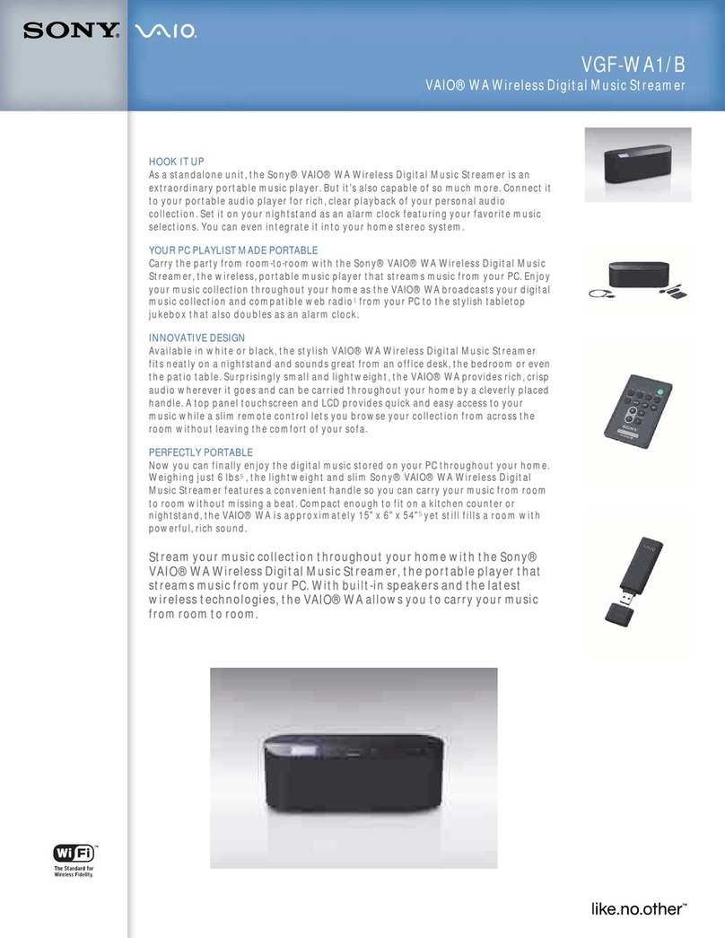
Be sure to use the remote control cable RCC-5G/10G
without attaching the spring lock plate.
Spring lock plate
OK NG
2 (E) HKSP-1125
2. Name and Function of Connector
11
11
1SDI IN (SDTV serial digital video signal input)
connector (BNC-type)
This connector inputs a SDTV serial digital video
signals of D1 SDI (525/625) and D2 SDI (525).
22
22
2VIDEO IN (NTSC analog video signal input)
connector (BNC-type)
This connector inputs an analog NTSC video signal.
33
33
3HD OUT (HDTV serial digital video signal
output) connectors (BNC-type)
The video signal input to the SDI IN and VIDEO IN
connectors is processed according to the operating
mode and then output.
The same signal is output from connectors 1 and 3.
44
44
49PIN/GPI connector (D-sub 9 Pin)
This connector is the input/output connector of an
external controls which connecting the HD digital
video controller HKDV-900.
Moreover, this connector can also be used as GPI. The
selection is performed by the menu of this unit.
3. Name and Function of Switch and
Indicator
The switches and indicators on the operation panel and
main board (DPR-215A board) are described below.
3-1. Operation Panel
REMOTE
(RS-422)
I
N
1
2
3
SDI IN
VIDEO IN
1125
HD OUT
P
U
T
U
O
T
P
U
T
1
2
4
3
HD UP-CONVERTER
HKSP-1125
PUSH
EXIT
ANALOG
AUDIO IN
REF IN
VIDEO IN
STATUS
D2 SDI
D1 SDI
9
0
!-
2
1
5
6
7
8
3
4

3 (E)
HKSP-1125
Dial and switch (Refer to Section 5-1-1 for operation.)
No. Ref. No. Name Function
1EN1 Dial Selects the setting item and data.
(LED-395A board) Select: Turn the dial.
Determine: Press the dial.
2S1 EXIT key Returns to the display mode when this switch is pressed in the input
(LED-395A board) mode.
Displays
No. Ref. No. Name Function
3ND1 Upper Display Displays the setup and operation data items.
(LED-394A board)
4ND2 Lower Display Displays the values of setup and operation data.
(LED-394A board)
Indicators
No. Ref. No. Name Function
5D1 STATUS Lights in green: Under normal operation
(LED-393A board) Blinks in green: A warning occurs. (Refer to Section 6-1-2.)
Blinks in red: An error occurs. (Refer to Section 6-1-1.)
Off: The power supply of the main board is abnormal or
CPU is not activated.
n
When an error and warning are occurred simultaneously, error
overrides the warning.
For details, refer to Sections 5-2 and 6.
6D2 VIDEO IN Lights in green: A SD video input signal is normal.
(LED-393A board) Lights in red: A SD video input signal is abnormal or dose not match
with the setting of a format.
Off: A SD video input signal does not exist.
7D3 REF IN Lights in green: A selected reference signal is normal.
(LED-393A board) Lights in red: A selected reference signal is abnormal.
Off: A selected reference signal does not exist.
8D4 AUDIO IN Lights in green: An audio input signal is normal.
(LED-393A board) Lights in red: An audio input signal is abnormal.
Off: An audio input signal does not exist.
9D6 D1 SDI Lights in green: A D1 SDI input mode is selected.
(LED-393A board) Off: Other mode is selected.
!/ D7 D2 SDI Lights in green: A D2 SDI input mode is selected.
(LED-393A board) Off: Other mode is selected.
!- D8 ANALOG Lights in green: An ANALOG input mode is selected.
(LED-393A board) Off: Other mode is selected.

4 (E) HKSP-1125
3-2. Main Board (DPR-215A Board)
Switches (Factory default settings are indicated by a \\
\\
\mark.)
No. Ref. No. Name Function
1S1901 RESET The DPR-215A board performs the same operation as during the power-on
sequence when this switch is pressed.
n
Do not use during normal operation.
2S600 STATUS Status out select switch
1-8 (\ON)
For details about this switch, refer to Section 5-2.
3S601 TEST Test switch
1-8 (\OFF)
n
Factory use only.
4S1900 NORM/DOWN CPU program rewrite switch
(\NORM)
n
Do not use during normal operation.
O
N
O
N
1
8
O
N
1
8
S1901
S1900
S601
S600
14 3 2

5 (E)
HKSP-1125
4. Operating Function
The HD up converter board HKSP-1125 converts the standard TV signal (SDI) to high definition TV
signal (HD SDI), and has an additional function required for conversion.
Input/Output
.Input signal can be selected from the following four video signals.
D1 SDI (59.94i)
D1 SDI (50i)
D2 SDI (59.94i)
NTSC ANALOG (59.94i)
.Output signal can be selected from the following four signal systems according to the selected signal
mentioned above.
1080i/59.94: D1 SDI (59.94i) /D2 SDI (59.94i) /NTSC ANALOG (59.94i)
1035i/59.94: D1 SDI (59.94i)/ D2 SDI (59.94i) /NTSC ANALOG (59.94i)
1080i/50: D1 SDI (50i)
720p/59.94: D1 SDI (59.94i) /D2 SDI (59.94i) /NTSC ANALOG (59.94i)
Genlock System
The sync signal of the output signal can be selected from internal sync INPT, external sync REFA and
REFB. If the external sync signal is selected, the frame synchronizer function operates automatically.
.Internal Synchronization Mode
m
.The system delay is fixed to 1Frame.
.When the unit is operating in this mode, the audio rate convert function can not operate irrespective of
the setting (ON/OFF) of the audio rate convert function ADRC.
The delay amount of audio is fixed to 1Frame. But, it is possible to adjust it by the system delay SYC,
SY-F and audio delay ADLY. (For more details, refer to Section “5. Setting”.)
0_1f 0_2f 1_1f 1_2f
0_1f 0_2f 1_1f 1_2f
1Frame
Video input signal
Video output signal

6 (E) HKSP-1125
.External Synchronization Mode (Frame Synchronizer Mode)
When the external sync signal is delayed α(660H or less).
When the external sync signal is advanced β(1Frame _660H or less).
n
When the unit is operating in this mode, the audio rate convert function is switched to ON/OFF according
to the setting (ON/OFF) of the audio rate convert function ADRC. The audio delay is fixed to 1Frame.
But, it is possible to adjust it by the system delay SYC, SY-F and audio delay ADLY. (For more details,
refer to Section “5. Setting”.)
Motion Sensitivity Adjustment Function
According to the motion, the ratio converts from a field or a frame is changed adaptively and processed.
The sensitivity can be adjusted in five steps.
Aspect Ratio
The aspect ratio of the output video signal can be selected from Edge crop, Letter Box, or Squeeze. The
position can be adjusted in each aspect ratio.
Color Corrector Function
The color corrector function can be selected from YPbPr, HUE, or RGB, and the white clip and black clip
adjustments can also be performed.
0_1f 0_2f 1_2f
0_1f 0_2f 1_1f 1_2f
0_1f 0_2f 1_1f 1_2f
1Frame + α
External sync signal
Video input signal
Video output signal
α
1_1f
0_1f 1_2f
0_2f 1_1f 1_2f
0_2f 1_1f 1_2f
1Frame −β
External sync signal
Video input signal
Video output signal
β
1_1f0_2f
0_1f
0_1f

7 (E)
HKSP-1125
Back-color Control Function
The back-color control function has the following features.
.Color adjustment of color matte
.Position adjustment for back-color area
.Enables the layout and super-impose of the intake picture into back.
Ancillary Data Multiplexing
Multiplexes the auxiliary data such as VITC, digital super imposed data, and so on to HD SDI signal.
Audio
Audio signal can be delayed up to 2 Frames, and corresponds to 8 channels.

8 (E) HKSP-1125
5. Setting
Each item can be set using the operation panel.
The operation of the operation panel and the setting of
setup switches on the main board are described below.
The several setting items and operation modes are always
stored, so it is not necessary to reset the settings by the
POWER ON/OFF etc.
5-1. Setting Using Operation Panel
5-1-1. Operation
Upper Display: Displays the item (menu).
Lower Display: Displays the set value.
Turn the dial clockwise: The item advances.
Turn the dial counterclockwise:
The item returns.
Press the dial: The hierarchy of a menu turns
into lower by one.
The set value is determined.
EXIT key: The hierarchy of a menu returns
by one.
n
For the configuration and hierarchy of a menu, refer to
Sections “5-1-2. Menu Configuration”and “5-1-3. Menu
List”.
Basic operation
1. Turn the dial and select the menu to be set.
2. Press the dial to turns into the lower hierarchy of a
menu by one.
3. When it is determined at the bottom of the hierarchy,
the display returns to the system menu.
n
The system automatically returns to the HOME menu
mode when, in the input mode, the state of no operation
continues over a fixed period of time (about 5 minutes).
HD UP-CONVERTER
HKSP-1125
PUSH
ANALOG
EXIT
AUDIO IN
REF IN
VIDEO IN
STATUS
D2 SDI
D1 SDI
Upper display
Lower display
Dial
EXIT key

9 (E)
HKSP-1125
Setting example 1 (Without the hierarchy of a
menu)
When setting the reference to REF IN A of signal process-
ing unit PFV-SP series
1. Turn the dial to display “REF”on the upper display.
The current setting is displayed on the lower display.
2. Press the dial. The lower display turns into the input
mode and blinks.
3. Turn the dial to display “REFA”(REF IN A as the
reference) and press the dial.
“REFA”is lit up and returns the display mode, then
the reference is set to REF IN A.
Setting example 2 (With the hierarchy of a menu)
When setting the video gain to 90 % in the color corrector
mode
1. Turn the dial to display “C/C”on the upper display.
The current setting (YpbPr) is displayed on the lower
display.
2. Press the dial to turns into the input mode.
3. Turn the dial to display the “HUE”, and press the dial.
The menu “VI-G”for the composite video signal is
displayed on the upper display. The current setting
value (“100 %”) is displayed on the lower display, and
its picture is fed out.
4. Press the dial to turns into the input mode.
5. Turn the dial to counterclockwise to display “90 %”.
The video gain is set to 90 %.
6. Press the dial once to turn the system into the higher
hierarchy by one.
7. Press the EXIT key twice to return the HOME menu.
5-1-2. Menu Configuration
The setting items are classified into three groups.
The current “FMT”of the HOME is displayed when the
power is turned on.
.HOME menu
Group of items that displays the current statuses of
MODE and format are contained.
.System menu
Group of functions (e.g., signal format, default recall)
that changes the system setting extensively during the
operation are contained.
n
To enter the system menu, press the dial 2 seconds or
more in the HOME menu.
.Operation menu
Group of items (e.g., color corrector function, enhancer
function) that changes the setting frequently during the
operation are contained.

10 (E) HKSP-1125
[IN-V] : Input video select
D1 : Selects D1 SDI
D2 : Selects D2 SDI
ANA : Selects NTSC ANALOG
[REF] : Video reference select
INPT : INPUT VIDEO
REFA : REF IN A
REFB : REF IN B
[EX-R] : External reference select
HD : Tri-level sync signal
SD : 525/625 black burst signal
[CONV] : Conversion mode
ADP : Adaptive
FLD : Converts at field fixation.
FRM : Converts at frame fixation.
[M-SE] : Motion detection sensitivity adjustment
1 : Adaptive 2
5 : Adaptive 3
[ASPC] : Aspect mode select
ON : Aspect menu ON
[ASPE] : Aspect ratio select
EC : Edge Crop mode
LB : Letter Box mode
SQ : Squeeze mode
[ECPC] : Edge Crop position control
ON : Variable
OFF: Fixed to center
[EC-P] : Edge Crop position adjustment
[LBPC] : Letter Box position control
ON : Variable
OFF: Fixed to center
[LB-P] : Letter Box position adjustment
[AS-F] : Aspect flag mode ON/OFF
OFF: Panel setting is effective.
ON : Follows flag of stream.
OFF : Aspect menu OFF
[C/C||] : Color corrector mode
YPb
HUE
RGB
Y[M-G] : Master gain adjustment
Y[Y-G] : Y gain adjustment
Y[Pb-G] : Pb gain adjustment
Y[Pr-G] : Pr gain adjustment
Y[SETU] : Setup adjustment
H[VI-G] : Video gain adjustment
H[CH-G] : Chroma gain adjustment
H[HUE] : HUE adjustment
H,R [OFFS] : Offset adjustment
R[M-G] : Master gain adjustment
R[R-G] : R gain adjustment
R[G-G] : G gain adjustment
R[B-G] : B gain adjustment
Y/R/H [WCL] : White clip level setting
Y/R/H [BCL] : Black clip level setting
. . .
. . .
_
Operation menu
5-1-3. Menu List
n
The menus for the color corrector mode are displayed as
follows.
Menu for RGB: Displays as “R”.
Menu for YPbPr: Displays as “Y”.
Menu for HUE: Displays as “H”.
[HOME]
[FMT] : Output format
108i/5994 : 1080i/59.94
103i/5994 : 1035i/59.94
108i/50 : 1080i/50
720p/5994 : 720p/59.94sF
[O||DL] : Selects output delay
REF : REF synchronization
ADJ : Variable
MIN : Minimum delay
[DL||A] : Adjusts delay amount
O O X X : Adjustment of grade of 100
XXOX : Adjustment of grade of 10
XXXO : Adjustment of grade of 1
[DL2F] : 2 Frames delay ON/OFF
OFF : 2 Frames delay OFF
ON : 2 Frames delay ON
[FS||P] : Frame synchronizer process select
FREZ : Outputs the picture just before intermit-
tent of signal.
GRAY : Outputs the gray picture.
[DEFA] : Default recall
OFF : No change
USER : User default setting
FACT : Factory setting state
[DF-S] : User default save
OFF : No change
SAVE : Save current setting to user default
[REMO] : 9-pin remote select HKDV-900/GPI
HKDV :
Use HD digital video controller HKDV-900
GPI : Use GPI
[V-SG] : Video SG
OFF : No output
1 : Color bars 100 % (709) select
16 : Grey select
[DIAG] : Self diagnosis mode
OFF : End
ON : Start
[SOFT] : CPU software version display
[PLD1] : PLD1 version display
[PLD2] : PLD2 version display
[HARD] : Hardware version display
: Error code display
: Warning code display
System menu
. . .
. . .
_
_
_

11 (E)
HKSP-1125
[BC] : Back-color control function ON/OFF
ON : Back-color control function ON
[BC-Y] : Back-color Y level adjustment
[BCPb] : Back-color Pb level adjustment
[BCPr] : Back-color Pr level adjustment
[BCLP] : Expand left-side area of back-color.
[BCRP] :
Expand right-side area of back-color.
SUP : Super impose (Displays when REF is set to INPT.)
[BCLP] : Expand left-side area of back-color.
[BCRP] :
Expand right-side area of back-color.
[CAP] : Capture a picture into memory.
ON : Performs capturing and inserts it.
OFF : No change
OFF : Back-color control OFF
[SETR] : Set-up remove function ON/OFF
OFF : Set-up remove function OFF
ON : Set-up remove function ON
[GAM] : Gamma correction function ON/OFF
ON : Gamma correction function ON
GAMM : Gamma curve
OFF : Gamma correction function OFF
[ENHC] : Enhancer function ON/OFF
ON : Enhancer function ON
DET : Detail signal gain adjustment
LIMT : Clip level setting
CRIS : Crispening level setting
LEVD : Compression amount setting
FREQ : H details frequency setting
H/V : H/V details signal mix ratio setting
OFF : Enhancer function OFF
[SYNC] : Sync phase coarse adjustment
[SY-F] : Sync phase fine adjustment
[ADRC] : Audio rate converter ON/OFF
OFF : Audio rate converter OFF
ON : Audio rate converter ON
[ADLY] : Audio delay ON/OFF
OFF : Audio delay OFF
ON : Audio delay ON
O X X X : Adjustment of grade of 1000
X O X X : Adjustment of grade of 100
X XO X : Adjustment of grade of 10
X X XO : Adjustment of grade of 1

12 (E) HKSP-1125
5-1-4. HOME Menu
Item Description
HOME Displays the input video (D1 SDI/D2 SDI/ANALOG input mode) on the upper display. (Displays the
contents of the IN-V (D1, D2, ANA) in the actual display.)
Displays the HD output format on the lower display. (Displays the number of scanning lines and frequency
alternately at intervals of 1 second.)
5-1-5. System Menu
n
To enter the system menu, press the dial in the HOME menu 2 seconds or more.
(Factory default settings are indicated by a \\
\\
\mark.)
Item Description
FMT Selects the output format. The number of scanning lines and frequency is displayed alternately at intervals
of 1 second on the lower display. When the dial is pressed, the number of scanning lines is displayed on
the upper display, and the frequency is displayed on the lower display, and the format can be selected.
D1 SDI input mode
Selects the D1 SDI input mode by IN-V, and selects the output format described below by FMT.
Display Output format
\108i/5994: 1080i/59.94
108i/50: 1080i/50
103i/5994: 1035i/59.94
720p/5994: 720p/59.94sF
D2 SDI input mode
Selects the D2 SDI input mode by IN-V, and selects the output format described below by FMT.
Display Output format
\108i/5994: 1080i/59.94
103i/5994: 1035i/59.94
720p/5994: 720p/59.94
ANALOG input mode
Selects the ANALOG input mode by IN-V, and selects the output format described below by FMT.
Display Output format
\108i/5994: 1080i/59.94
103i/5994: 1035i/59.94
720p/5994: 720p/59.94
O_DL Adjusts the output delay amount.
\REF: REF synchronization (When the REF is set to INPUT, the delay amount is set to 1 frame. When
the REF is set to REFA or REFB, the frame synchronizer operates, and then the delay amount is
variable in the range of about 0.6 frame to 1.6 frame.)
ADJ: Variable
MIN: Minimum delay
n
When the mode is in ADJ or MIN, the frame synchronizer is set to OFF forcibly.
DL_A Adjusts the delay amount. (Only when O_DL is set to ADJ, this mode is enabled.)
Sets the delay amount in the units of line, and setup is possible to 660 to 1171 lines.
OOXX: The grade of 100 blinks. Sets the value from 6 to 11 by turning the dial, and press the dial to
determination. Shifts the grade of 10 by pressing the dial againÅCand shifts the grade of 1000 by
pressing the EXIT key.
XXOX: The grade of 10 blinks. Set the value from 0 to 9 by turning the dial, and press the dial to
determination. Shifts the grade of 1 by pressing the dial againÅCand shifts the grade of 100 by
pressing the EXIT key.
XXXO: The grade of 1 blinks. Set the value from 0 to 9 by turning the dial, and press the dial to determi
nation.
DL2F 2 frames delay (Adds 1 frame to the normal delay amount of video and audio.)
\OFF: No change
ON: 2 frames delay

13 (E)
HKSP-1125
Item Description
FS_P Selects the frame synchronizer process (Selects the output picture at the time of the input signal is
intermittent.)
\FREZ: Outputs the picture just before intermittent of signal.
GRAY: Output the gray picture.
n
When the external sync is selected as the REF signal, the frame synchronizer operates automatically.
DEFA Changes the setting into default setting.
\_OFF: Not change the setting.
USER: Changes the setting into the contents that is saved in DF-S.
FACT: Changes the setting into the default settings of the factory shipping state.
n
If the setting is not saved in DF-S, the default setting of the USER is the same as the factory shipping state.
DF-S Saves the current setting as the user default.
\_OFF: Not save the setting
SAVE: Saves the setting.
REMO Selects the 9 pin remote.
\HKDV: Selects this mode when controlling the unit using a HD digital video controller HKDV-900.
GPI: Selects this mode when controlling the unit using GPI.
m
.The HD digital video controller HKDV-503 cannot be used. Be sure to use the HKDV-900.
.Even if the HKDV-900 is used, the unit can also be controlled by the front panel.
n
The following table shows the functions of the video controller and control function of this unit.
The Omark means the controllable function.
For the items displayed as Enhancer etc. after the Omark, these items become controllable by pressing
the Enhancer button of the HKDV-900.
The Xmark means the uncontrollable function.
Function Item Menu of the unit HKDV-900
Video/REF select All OX
Conversion All OX
Aspect Edge Crop OOEnhancer
Letter Box OOEnhancer
Squeeze OOEnhancer
Edge Crop Position OOEnhancer
Letter Box Position OOEnhancer
Aspect flag OX
Color Corrector YPbPr OOHD (Selectable to RGB)
HUE OOD2
RGB OOHD (Selectable to YPbPr)
White clip OX
Black clip OX
Setup Remover (7.5 %) OOD1
Back-color Back-color Y Level OOD1
Back-color Pb Level OOD1
Back-color Pr Level OOD1
Back-color Left Position OX
Back-color Right Position OX
Gamma Correction All OOEnhancer
Enhancer All OOEnhancer
Sync Phase All OOHD
Audio Delay All OX

14 (E) HKSP-1125
Item Description
n
The HKSP-1125 operates as the following GPI specifications.
.Pin assignment
Pin Control
3 pin LOW = REMOTE
HIGH = LOCAL (When LOCAL is selected, following pins
cannot be controlled by GPI too.)
5 pin LOW = SQUEEZE
HIGH = Follows the setting of 8 pin.
8 pin LOW = LETTER BOX
HIGH = EDGE CROP
.Pin input TTL level
LOW <1.5 V
HIGH >3.5 V
V-SG Starts up the VIDEO SG and selects the output signal.
\OFF: Does not output the video signal. (The input video signal is processed and output directly.)
1: Color Bars 100% (709)
2: Color Bars 75% (709)
3: Vertical Color Bars 100% (709)
4: Vertical Color Bars 75% (709)
5: Ramp
6: Ramp with Chroma
7: 10 steps
8: 5 steps
9: Cross Hatch
10: Dot
11: Box1
12: Box2
13: Vertical Ramp
14: Vertical Ramp with Chroma
15: 100% White
16: Gray
DIAG Self diagnosis mode
\OFF: Ends the self diagnosis mode.
ON: Starts the self diagnosis mode.
n
The DIAG display blinks during self diagnosis mode, and when 60 seconds are left to the end of the self
diagnosis, the counts down starts. When the diagnosis is ended, lights up the DIAG display.
If the error is not existed, E-OK is displayed on the lower display.
If the error is existed, error number is displayed on the lower display.
n
For details of the diagnosis results, refer to Section “6-2. Self Diagnosis Mode Error Code List”.
m
When the EXIT key is pressed during DIAG, the diagnosis operation is interrupted and ended.
.The display during DIAG is controlled normally.
.The DIAG operation takes about one minute from a start to an end.
SOFT Displays the version of CPU software on the lower display.
n
There is no hierarchy in this menu. Therefore, even if the dial is pressed, an item does not change.
PLD1 Displays the version of PLD mounted on the main board on the lower display.
n
There is no hierarchy in this menu. Therefore, even if the dial is pressed, an item does not change.
PLD2 Displays the version of PLD mounted on the connector board on the lower display.
n
There is no hierarchy in this menu. Therefore, even if the dial is pressed, an item does not change.

15 (E)
HKSP-1125
Item Description
HARD Displays the version of hardware on the lower display.
n
There is no hierarchy in this menu. Therefore, even if the dial is pressed, an item does not change.
ERR! Displays the error code generated in this unit.
When an error occurs in the error item being selected by STATUS_OUT SW, the error is displayed.
When two or more errors occur, an error code is switched at intervals of 1 second, and is displayed.
When there is no error, - - - - is displayed.
n
For details of the error code, refer to Section “6-1-1 Error”.
WRN! Displays the warning code generated in this unit.
When a warning occurs in the warning item being selected by STATUS_OUT SW, the warning is dis-
played.
When two or more warnings occur, a warning code is switched at intervals of 1 second, and is displayed.
When there is no warning, - - - - is displayed.
n
For details of the warning code, refer to Section “6-1-2 Warning”.

16 (E) HKSP-1125
5-1-6. Operation Menu
(Factory default settings are indicated by a \\
\\
\mark.)
Item Description
IN-V Selects input video mode.
\D1: Selects D1 SDI input mode (525/626).
D2: Selects D2 SDI input mode (525).
ANA: Selects NTSC ANALOG input mode (525).
REF Selects the reference of the HD-SDI output signal.
\INPT: Sets the INPUT VIDEO as the reference.
REFA: Sets the REF IN A of the connector board on the PFV-SP series as the reference.
REFB: Sets the REF IN B of the connector board on the PFV-SP series as the reference.
n
When the REFA or REFB is selected as the REF signal, and when its selected signal is not inputted, the
INPT is selected automatically.
EX-R Selects the format of the reference input signal.
\HD _: Tri-level sync signal
SD _: 525/625 black burst signal
CONV Selects the conversion mode.
\ADP: Adaptive (Motion adaptive field/frame conversion)
FLD: Converts at field fixation.
FRM: Converts at frame fixation.
M-SE Adjusts the motion detection sensitivity during converting. (This mode is effective only when CONV is set
to ADP.)
By this sensitivity, the conversion ratio from Frame or Field at the time of conversion can be changed. If a
numerical value is enlarged, the sensitivity of motion sensor becomes high. As the result, the portion
processed as the animation increases. (When the output mode is 720p, 2 to 4 can only be selected.)
1: adaptive2 (Still picture priority mode)
2: adaptive1-S
\3: adaptive1 (Standard mode)
4: adaptive1-M
5: adaptive3 (Animation priority mode)
ASPC Selects the aspect mode.
OFF: Edge Crop mode (Default)
\ON: Opens the aspect menu.
ASPE Selects the aspect ratio.
\ECN: Edge Crop mode
LB: Letter Box mode
SQ: Squeeze mode
ECPC Edge Crop Position Control
OFF: Fixed to center.
\ON: Variable
EC-P Adjusts the Edge Crop position. (In the units of 2 pixels.)
Factory setting: 0
Setting range: _240 to +240 (at 1080 output)
_160 to +160 (at 720p output)
LBPC Letter Box Position Control
OFF: Fix to center.
\ON: Variable
LB-P Adjusts the Letter Box Position (This mode is only effective when LBPC is set to ON.)
Factory setting: 0
Setting range: _31 to +32 (at 1080i/59.94 output, and the center is 52 lines.)
_36 to +36 (at 1080i/50 output, and the center is 59 lines.)
_30 to +30 (at 720p output, and the center is 52 lines.)
n
The variable can be performed in the unit of one line. When the setting is set to maximum value, the
picture is positioned to the lower most position, and set to minimum value, the picture is positioned to the
upper most position.

17 (E)
HKSP-1125
Item Description
AS-F Selects the aspect flag mode.
\OFF: The panel setting is turned effective.
ON: Follows flag of stream.
n
When the aspect flag is set to ON, and when the aspect identifying flag is set to 16 lines of the input
signal, the output aspect is controlled irrespective of the aspect setting of the unit and aspect setting of the
HKDV-900.
Aspect identifying flag is existed →Outputs the Squeeze mode.
Aspect identifying flag is not existed →Outputs the Edge Crop mode.
C/C Selects the system when performing the color correction.
The menu displaying by each selection differs.
\YPb: The color adjustment by YPbPr is possible.
M-G: Adjusts the master gain.
Factory setting: 100 %
Adjusting range: 0 to 141 % (in units of 1 %)
Y-G: Adjusts the Y-ch gain.
Factory setting: 100 %
Adjusting range: 0 to 141 % (in units of 1 %)
Pb-G: Adjusts the Pb-ch gain.
Factory setting: 100 %
Adjusting range: 0 to 141 % (in units of 1 %)
Pr-G: Adjusts the Pr-ch gain.
Factory setting: 100 %
Adjusting range: 0 to 141 % (in units of 1 %)
SETU: Adjusts the setup.
Factory setting: 0 %
Adjusting range: _10 % to +10 % (in units of 0.5 %)
WCL: Sets the white clip level.
Factory setting: OFF
Setting range: 93 % to 108 % (in units of 1 %)
BCL: Sets the black clip level.
Factory setting: OFF
Setting range: _6 % to +7 % (in units of 1 %)
HUE: The color adjustment by composite is possible.
VI-G: Adjusts the video gain.
Factory setting: 100 %
Adjusting range: 0 % to 141 % (in units of 1 %)
CH-G: Adjusts the chroma gain.
Factory setting: 100 %
Adjusting range: 0 % to 141 % (in units of 1 %)
HUE: Adjusts the hue.
Factory setting: 0 d
Adjusting range: _30 dto +30 d(in units of 1 d)
OFFS: Adjusts the offset.
Factory setting: 0 %
Adjusting range: _10 % to +10 % (in units of 0.5 %)
WCL: Sets the white clip level.
Factory setting: OFF
Setting range: 93 % to 108 % (in units of 1 %)
BCL: Sets the black clip level.
Factory setting: OFF
Setting range: _6 % to +7 % (in units of 1 %)

18 (E) HKSP-1125
Item Description
RGB: The color adjustment by RGB is possible.
M-G: Adjusts the master gain.
Factory setting: 100 %
Adjusting range: 0 % to 141 % (in units of 1 %)
R-G: Adjusts the R-ch gain.
Factory setting: 100 %
Adjusting range: 0 % to 141 % (in units of 1 %)
G-G: Adjusts the G-ch gain.
Factory setting: 100 %
Adjusting range: 0 % to 141 % (in units of 1 %)
B-G: Adjusts the B-ch gain.
Factory setting: 100 %
Adjusting range: 0 % to 141 % (in units of 1 %)
OFFS: Adjusts the offset.
Factory setting: 0 %
Adjusting range: _10 % to +10 % (in units of 0.5 %)
WCL: Sets the white clip level.
Factory setting: OFF
Setting range: 93 % to 108 % (in units of 1 %)
BCL: Sets the black clip level.
Factory setting: OFF
Setting range: _6 % to +7 % (in units of 1 %)
OFF: Sets the color corrector function to OFF.
BC Back-color control function (Color matte function)
In the Edge Crop mode, the color can be added to the black portion on both sides. The designation of
color can be adjusted by the level of three signal of Y, Pb and Pr signals in the unit of 1 %.
For the signal with the wide blanking width like an analog signal, it is possible to expand the widths of the
right and left sides to add the back-color.
\ON: Turns On the back-color control.
BC-Y: Back-color Y level. (Default is 40.)
BCPb: Back-color Pb level (Default is 200.)
BCPr: Back-color Pr level (Default is 200.)
BCLP: Expands the left side area of back-color. (0 to 32 pixels, default is 0.)
BCRP: Expands the right side area of back-color. (0 to 32 pixels, default is 0.)
SUP: Insert the picture that is converted by Squeeze mode instead of the back color.
This menu is displayed only when the REF is set to INPT. If REFA or REFB is selected, this
function cannot be used.
CAP: Memorize the picture that is converted by the Squeeze mode into the memory.
OFF: No change
ON: Executes capturing, and inserts its picture to the side of the Edge Crop.
n
Be sure to select the CAP and ON in the Squeeze mode.
The capturing cannot be performed in the Edge Crop mode.
The picture that was captured will be erased when the power of the signal processing unit is
turned OFF, when except SUP is selected in BC mode, and when the REFA or REFB is selected
in the REF.
OFF: Turns the back-color control to OFF.
SETR Set-up remove function
\OFF: Performs the usual conversion.
ON: Removes the 7.5 % set-up, and converts.
n
This mode is only effective when the input signal is analog composite (NTSC) or D2 SDI (NTSC) signal.
GAM Controls the gamma correction function.
ON: Sets the gamma correction function to ON.
Factory default setting: 0.45
Setting range: 0.38 to 0.52 (in units of 0.01)
\OFF: Sets the gamma correction function to OFF.
n
The specifications of both Inv-γand γconform to ITU-R BT.709 standard, and the default setting of the γis
ITU-RBT.709.
Other manuals for HKSP-1125
1
Table of contents
Other Sony Media Converter manuals

Sony
Sony MVE-8000 User manual

Sony
Sony CarrierGate PCWA-DE50 User manual

Sony
Sony DVMC-DA1 User manual

Sony
Sony XV-T33 - Video Sketch Titler User manual

Sony
Sony VAIO PCWA-DE30 User manual

Sony
Sony MKS-6550 User manual

Sony
Sony SRP-F300 User manual

Sony
Sony HDRC-4000 User manual

Sony
Sony BKSR-2025 User manual

Sony
Sony BKPF-012A User manual

Sony
Sony DVMC-DA1 User manual

Sony
Sony BKSI-2020 User manual

Sony
Sony BKPF-L752 User manual

Sony
Sony TDM-NC1 - Wi-fi Client For Streaming Music User manual

Sony
Sony HVBK-1520 User manual

Sony
Sony MEU-WX1 User manual

Sony
Sony DFR-E3000 User manual

Sony
Sony NSBK-A16H User manual

Sony
Sony DVMC-DA2 User manual

Sony
Sony NXLK-IP50Y User manual