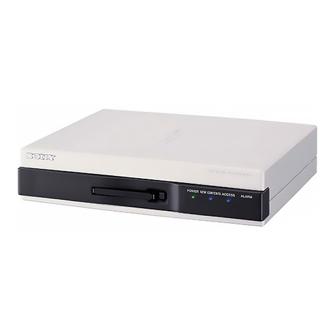
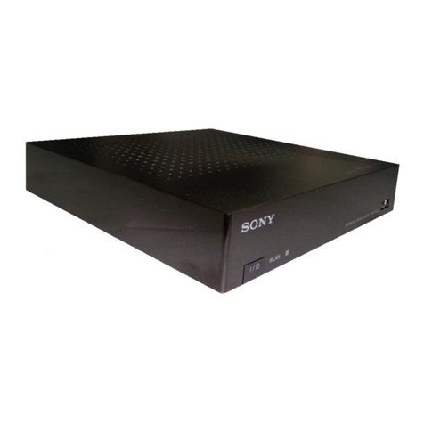
Sony NSP-1 User manual

3-855-936-14(1)
Network Player
© 2004 Sony Corporation
NSP-1
Operating Instructions
Before operating the unit, please read this manual thoroughly and retain it for future
reference.

2
To reduce the risk of fire or electric shock,
do not expose this apparatus to rain or
moisture.
To avoid electrical shock, do not open the
cabinet. Refer servicing to qualified
personnel only.
IMPORTANT
The nameplate is located at the left side.
For the customers in the USA
This equipment has been tested and found to comply with
the limits for a Class A digital device, pursuant to Part 15
of the FCC Rules. These limits are designed to provide
reasonable protection against harmful interference when
the equipment is operated in a commercial environment.
This equipment generates, uses, and can radiate radio
frequency energy and, if not installed and used in
accordance with the instruction manual, may cause
harmful interference to radio communications. Operation
of this equipment in a residential area is likely to cause
harmful interference in which case the user will be
required to correct the interference at his own expense.
You are cautioned that any changes or modifications not
expressly approved in this manual could void your
authority to operate this equipment.
All interface cables used to connect peripherals must be
shielded in order to comply with the limits for a digital
device pursuant to Subpart B of Part 15 of FCC Rules.
For the State of California, USA only
Perchlorate Material - special handling may apply, See
www.dtsc.ca.gov/hazardouswaste/perchlorate
Perchlorate Material : Lithium battery contains
perchlorate.
For the customers in Europe
This product with the CE marking complies with the EMC
Directive issued by the Commission of the European
Community.
Compliance with this directive implies conformity to the
following European standards:
• EN55103-1: Electromagnetic Interference (Emission)
• EN55103-2: Electromagnetic Susceptibility (Immunity)
This product is intended for use in the following
Electromagnetic Environments: E1 (residential), E2
(commercial and light industrial), E3 (urban outdoors),
E4 (controlled EMC environment, ex. TV studio)
WARNING
Use an AC power adapter provided with this equipment as
a power supply source. Any other power sources may
result in hazards such as a fire.
This product has no power switch.
Disconnect device of this equipment is the mains plug of
the AC adapter.
The mains plug on this equipment must be used to
disconnect mains power. Please ensure that the socket
outlet is installed near the equipment and shall be easily
accessible. In the event of abnormal operations, disconnect
the mains plug.
Voor de Klanten in Nederland
• Gooi de batterij niet weg maar lever deze in als klein
chemisch afval (KCA).
• Dit apparaat bevat een vast ingebouwde batterij die niet
vervangen hoeft te worden tijdens de levensduur van het
apparaat.
• Raadpleeg uw leverancier indien de batterij toch
vervangen moet worden. De batterij mag alleen
vervangen worden door vakbekwaam servicepersoneel.
• Lever het apparaat aan het einde van de levensduur in
voor recycling, de batterij zal dan op correcte wijze
verwerkt worden.
For the customers in Taiwan only
WARNING

3
Table of Contents
Table of Contents
Features .......................................................4
Names and Functions of Parts...................5
Front Panel.................................................... 5
Rear Panel..................................................... 6
System Configuration .................................8
Installation .................................................... 9
Setup ............................................................9
Preparation.................................................... 9
Opening the Setup Pages .............................. 9
Selecting a Language.................................. 10
System Setup .............................................. 10
User Setup................................................... 11
Making Account Settings ........................... 13
When All of the Settings for All of Pages Are
Completed ......................................... 13
Confirming the Status of this Unit...........14
Installing the BZNP-D1LE .........................14
Downloading Sample Material .................15
Precautions................................................15
Precautions for products with built-in HDD15
Others.........................................................16
Specifications.............................................. 16
Time Difference World Map ...................... 18

4Features
Features
The NSP-1 Network Player plays back (decodes) video/
audio data in MPEG format, outputting an analog signal. It
is the ideal digital content player for advertising,
presentations, training, and other situations.
The following are the principal features of this system.
High Image Quality
Plays MPEG-2 MP@ML encoded movies and full-color
still images and Web screen, providing an image quality
comparable to that of a DVD player.
Superimposed Movies, Stills, and Text
With a playlist, you can specify movies, stills, and
superimposed captions to be displayed simultaneously on
the monitor for specified durations.
Large Storage Capacity
The unit incorporates a 40-GB hard disk drive. This holds
about six hours and 30 minutes of video compressed to a
bit rate of 8 Mbps, or about 13 hours of video at 4 Mbps. 1)
1) Figures for storage times are for storing movies only. Depending on how
the system is used, the actual movie storage capacity may be less than
these figures.
Wide Range of Interfaces Supported
• Analog video input: Composite video input is available.
This allows you to overlay moving images sent from a
VTR or DVD over a still image.
• Analog audio input: Two input channels (left and right)
are available. This allows the unit to output mixed audio
signals input from a VTR or DVD.
• Analog video output: Composite video output is
available.
• Analog audio output: Two output channels (left and
right) are available.
• 10BASE-T/100BASE-TX: Network connection is
possible.
• GPI: This allows remote control of the monitor and other
external devices connected to this unit.
Image Rotation on the monitor screen display
Since you can rotate the direction of the still image
displayed, you are not required to create still images for
vertical display.
Compact and Lightweight
The dimensions (width/height/depth) are 210 ×44 ×167
mm (8 3/5×1 3/4×6 5/8inches), and the unit weighs only
about 1.5 kilogram (3 lb 6 oz), despite incorporating a
large-capacity hard disk drive.

5
Names and Functions of Parts
Front Panel
aPC card
Use only the supported PC card.
For detailed information on the supported PC card, consult
your nearest Sony dealer.
At the factory, a dummy card has been inserted. When you
use a real PC card, remove the dummy PC card. Retain the
dummy card. When a PC card is not being used, be sure to
keep the dummy card inserted in the slot. If the dummy
card is removed and nothing is inserted in the PC card slot,
the ventilation of the unit does not work correctly.
bPOWER indicator
This lights when power is supplied to the unit.
cNEW CONTENTS indicator
This indicator is off, or lit, to indicate the status of new
content delivery.
Lit: New data has arrived.
Off: At least one item of new data has been played or
deleted.
dACCESS indicator
This indicator flashes while data is being read or written to
the internal hard disk drive.
eALARM indicator
This flashes when a system error has occurred.
When this indicator is flashing, an error has occurred.
Contact your nearest Sony dealer.
3NEW CONTENTS indicator
1PC card
5ALARM indicator
2POWER indicator
4ACCESS indicator
Note

6Names and Functions of Parts
Rear Panel
a(network) connector (RJ-45 modular jack)
This is a 10BASE-T/100BASE-TX connector for network
(Ethernet) connection.
For safety, do not connect the connector for peripheral
device wiring that might have excessive voltage to this
port. Follow the instructions for this port.
bAUDIO IN L/R connectors (pin jacks)
These input analog audio signals.
cVIDEO IN connector (pin jack)
This inputs the analog composite video signal.
dAUDIO OUT L/R connectors (pin jacks)
These output the playback audio as an analog signal. For a
stereo signal, connector L outputs the left channel, and
connector R outputs the right channel
eVIDEO OUT connector (pin jack)
This outputs the playback video as a composite signal.
fReset button
Used to forcibly restart this unit when it hangs or freezes.
Push this button using a sharply pointed tools, such as a
pencil or stretched paper clip.
gDip switches
Used for various services. Set all switches to OFF.
1(Network) connector
5VIDEO OUT connector
2AUDIO IN L/R connectors
4AUDIO OUT L/R connectors
0GPI connector
6Reset button
9Cable lock
7Dip switches
qa (SERIAL) connector
qs (Analog RGB OUT) connector
qd USB connectors
8DC IN 13.5V connector/Metal cable
retainer
3VIDEO IN connector
Caution

7
Names and Functions of Parts
hDC IN 13.5V connector/Metal cable retainer
Connect the DC cable of the supplied AC adapter to this
connector.
After connecting the DC cable, it is recommended that you
attach the supplied metal cable retainer to prevent the DC
cable from being accidentally disconnected.
iCable lock
Attach a security cable to prevent the unit from being
stolen.
jGPI (general purpose interface) connector (D-sub
25-pin, female)
This is a parallel interface connector.
For detailed information on this connector, contact your
nearest Sony dealer.
k(SERIAL) (general purpose interface)
connector (D-sub 9-pin, male)
Connect this to the D-sub 9-pin connector of a plasma
display or video monitor to allow you control those
devices.
l(Analog RGB OUT) (general purpose interface)
connector (HD D-sub 15-pin, female)
Connect this to the VGA connector of a plasma display or
video monitor.
mUSB connectors
Connect only a device that supports the USB interface.
For detailed information on devices that support the USB
interface, consult your Sony dealer or a Sony service
representative.
After connecting the DC
cable, attach the supplied
metal cable retainer.

8System Configuration
System Configuration
The following diagram shows an example of a typical
system configuration.
VTR/tuner
Plasma display
Audio output
connectors
Speaker Speaker
RS-232C Analog RGB
connector
AUDIO OUT R connector
AUDIO OUT L connector
Video output connector
AUDIO IN L connector
AUDIO IN R connector
(SERIAL) connector
Network
connector
Internet/Intranet
Computer
Network
(BZNP-D1 software runs
on this computer.)
VIDEO IN connector
Analog RGB
OUT
connector

9
Setup
Installation
This unit is designed to be operated in either a horizontal
or vertical position.
If you wish to install this unit vertically, use the supplied
stand and mount this unit on the stand as illustrated. If this
unit is mounted in the wrong direction, it is likely to
malfunction.
Setup
This section described the settings you should make to use
this unit for the first time.
The following pages are used for system setup.
• System Settings page (see page 10)
Used to make settings for items such as system date and
time, and others related to network, displays, and so on.
• User Settings page (see page 11)
Used to make settings for items such as recover mode,
play log settings and so on.
• Account Settings page (see page 13)
Used to make settings for user names and passwords.
When you use this unit first time, make the required
settings according to the procedures described below.
When you want to change settings, follow the procedure
given for the corresponding items on the page.
About the Advanced Settings page
Systems administrator privileges are not required to make
settings on this page. This page is prepared for service or
special settings. This page is not used for daily operation.
Preparation
Access the setup page from the Web browser.
For detailed information on how to access the setup pages
from the Web browser, first download the manual. To do
this, refer to “Downloading the Manual” explained in the
Operation Guide of the printed manual supplied with this
unit.
For details, refer to the Operation Guide.
Opening the Setup Pages
1
Turn the power of the computer on.
2
Turn the power of the unit on.
3
Start the Web browser (Internet Explorer).
4
Enter a URL.
Enter the following default address and port number
set at the factory.
http://192.168.0.1:4980
5
Press the ENTER key.
The confirmation dialog box appears.
6
Enter the user name and password.

10 Setup
Enter the following user name and password set at the
factory.
User name: NSP1admin
Password: NSP1admin
Be sure to change the password set at the factory for
safety.
For detailed information on how to change the
password, see “Making Account Settings” on page 13.
7
Click the “OK” button.
The Status page opens.
Selecting a Language
You can select the language used on the setup pages.
To display the setup pages in Japanese: Click “ ”.
To display the setup pages in English: Click “English”.
System Setup
The System Settings page is used to make general system
settings such as system date and time, networks, displays,
and so on. Also, this page allows you to verify system
information
Opening the System Settings page
Click the “System Settings” button.
The System Settings page opens.
Setting/changing the system date and time
1
Enter the date (year/month/day) and time (hours/
minutes) in the “Change Time” column.
2
Enter the time zone.
Enter the time difference from UTC.
For detailed information on the time difference, see
the time difference world map on page 18.
3
Click the “Send” button.
The date and time information is sent to the unit.
The date and time can be set or changed only by
clicking the “Send” button to send the information to
the unit.
However, whenever you change the time zone, be sure
to carry out the following operation.
However, if you intend to continue the setup
operation, it is not necessary to carry out the following
step.
Make the settings on each page, as required. When all
of the desired settings are completed on each page, be
sure to click the “Reboot” button on that page.
4
Click the “Reboot” button.
The unit is powered off once, and then powered on
again.
The time zone of this unit is switched to the one
entered in step 2.
When a “ON” is selected indicating an NTP server is to be
used on page 11, the date and time set on this page are
adjusted according to the time information sent from the
NTP server after a while.
Making the system settings
1
Enter the name of this NSP-1
The name set here is used for entries made in the log.
This is useful when multiple NPS-1s are managed.
2
Set the network address.
When a wireless LAN is used:
Select “Yes” from “Wireless LAN.”
Enter the ESSID (Extended Service Set ID) in the
“ESSID” text box and the WEP (Wired Equivalent
Privacy) key in the “WEP key” text box, if required.
Enter the ESSID using alphabettical and numeric
characters.
Ask the network administrator for both.
Be sure not to connect the network cable to the
network connector on the unit, when a wireless LAN
is used.
When a wireless LAN is not used:
Select “No” from “Wireless LAN.”
When a DHCP server is used:
Select “Yes” from “DHCP”.
The IP address, subnet mask, and default gateway
address are obtained automatically.
After this unit is turned off and then turned on when
you click the “Reboot” button, addresses
automatically obtained are displayed.
When a DHCP server is not used:
Select “No” from “DHCP”.
Note
Note
Note
Note
11
Setup
Enter the following parameters:
IP Address: Enter the IP address for this unit.
Subnet Mask: Enter the subnet mask of the network
where the unit is to be used.
Default Gateway: Enter the IP address of the default
gateway.
3
Make settings related to the DNS server.
When a DNS server is not used:
Select “No” from “DNS Sever”.
When a DNS server is used:
Select “Yes” from “DNS Sever”.
Enter the IP address of the DNS server set for the
network (Internet/intranet) to which this unit is
connected.
For detailed information on the address, ask your
network administrator.
4
Make settings related to the proxy server.
When a proxy server is used:
Select “Yes” from “Proxy Server”.
Enter the address and the port number in the “Address”
text box and “Port” text box respectively.
Enter the address to be accessed without using a proxy
divides with a “,” (comma) in the “Address for Proxy
Server Bypassing” text box.
Ask the network administrator for the address and the
port number.
When a proxy server is not used:
Select “No” from “Proxy Server”.
5
Make settings related to the NTP server.
Select whether or not the built-in clock is to be
adjusted via the network.
When an NTP server is not used
Select “No” from “NTP Server”.
When a NTP server is used:
Select “Yes” from “NTP Server”.
Enter the IP address of the NTP server to be used.
When “Yes” is selected indicating a NTP server is to
be used, the system date and time are set according to
the time information sent from the NTP server.
6
Make settings for “Display.”
You can make the following settings:
Resolution: Set the screen resolution to be used.
Orientation: You can select one from among
“Landscape”, “Portrait (Counter Clockwise)” or
“Portrait (Clockwise)” based on the orientation of the
plasma display.
• When “Portrait (Counter Clockwise)” or “Portrait
(Clockwise)” is selected, the resolution and layout of
the material are restricted.
• The VIDEO OUT connector located on the rear
panel of the unit is activated only when “Composite”
is selected from “Resolution,” and “Landscape” is
selected from “Orientation.” The images output
from this connector will not be displayed correctly
except with the settings described above.
• When “Composite” is selected from “Resolution,”
images will not be displayed correctly on a plasma
display or video monitor connected to the
(analog RGB OUT) connector.
7
Select the video input/output signal format.
Select either “NTSC” or “PAL” from “Video”.
8
Click the “Send” button.
The settings made on this page are sent to the NSP-1.
To resume the setup operation, go to another page
without carrying out step 9.
9
Click the “Reboot” button.
This unit is turned off and turned on again. Settings
made are then valid.
To verify the information related to this unit
You can verify the software and hardware version of the
unit on the System Settings page.
User Setup
This page allows you to make settings for creating play
logs and for the recovery mode of the hard disk.
Opening the User Settings page
Click the “User Settings” button.
The User Settings page opens.
Making user settings
1
Make settings for the playout log.
You can select whether or not playout logs sent from
this unit are saved.
To save playout logs: Select “Yes” from “Playout
Log”.
To discard playout logs: Select “No” from “Playout
Log”.
Note
Notes

12 Setup
To specify the number of days to keep playout
log records
Enter the number in the “Period XX days” box.
2
Set the start time for the hard disk sleep.
To maintain the functions of the hard disk of this unit,
this unit allows the hard disk to sleep for about five
minutes once a day.
Set the start time of this sleep period (hour/minute) in
the “Start from” boxes.
For safe operation of the system, this unit carries out a
maintenance process, turns off once and then on again
automatically once a day. Thus, it cannot play
materials nor receive files during these minutes of
sleeping. It is recommended that you set the time for a
time of day when the schedule is affected as little as
possible. 00:00 a.m. is the default time. Change the
time as required.
3
Make settings for automatic deletion of materials.
By setting a time for automatic deletion when
materials are registered, materials are automatically
deleted at the specified period.
To activate the automatic delete function: Select
“Yes” from “Automatic Contents Deletion”.
To not activate the delete function: Select “No”
from “Automatic Contents Deletion”.
4
Make settings for serial communication on the “Serial
Communication” column.
Make settings for serial communication to control
external devices such as PDP.
Select the purpose of use of the (SERIAL)
connector located on the rear panel of the unit. Select
“External Device Control” to control external devices
using the firmware installed in the unit. Usually use
the unit with “External Device Control” selected.
Select “NSP-1 Control from Host” to control the unit
from external devices using the RS-232C control
function of this unit.
Communication speed: Select the communication
speed from the “Speed (bps)” drop down list box.
Parity: Select the communication parity from “Parity”
drop down list box.
Time out: Set the time out for response from devices.
5
Make settings for the screen saver.
To use the screen saver function: Select “Yes” from
“Built-in Screen Saver”.
To not use the screen saver function: Select “No”
from “Built-in Screen Saver”.
This setting works for the default screen sever only.
6
Make settings for the Web screen on the “Web Page”
column.
Select the font and font size (pixels) to be used on the
Web screen.
You can select whether the normal error screen or a
specific still picture is displayed when an HTTP
connection error occurs with “Screen upon
Connection Failure”.
To use normal error screen display: Select
“Default”.
To use a specific still picture: Select “Specified”.
Select the index number of the still picture to be used
in the display.
You can select whether the displayed page is stored in
the NSP-1 with “Cache Use”. The page stored is
displayed when an HTTP connection error occurs.
However, stored data is cleared when starting up or
restarting.
To use a cache: Select “Yes”.
To not use a cache: Select “No”.
When you select “Yes” for “Cache Use”, be sure to
select “Default” for “Screen upon Connection
Failure”. If you select “Specified” for “Screen upon
Connection Failure”, the setting of “Yes” for “Cache
Use” becomes invalid, even if you select “Yes”.
7
Make settings for the video contrast (an external input
is included) on the “Video Contrast” column.
8
Adjust the audio level for each piece of material on the
“Audio Level” column.
“PCM” indicates the material of audio file and flash
file.
Make settings for the audio mix when audio files exist
for two or more piece of material reproduced
simultaneously on “Audio Output” column.
To output all materials mixed: Select “Mixed”.
When the sound of Audio and Flash is given
priority and output as video sound: Select “PCM”.
9
Select the recovery mode from the “Substitute for
Missing Material”column.
You can select the mode to be used when a
transmission error occurs during scheduled playback,
for example, when there is no material registered in the
schedule.
To display nothing: Select “No Contents” from
“Recovery Mode”.
To display material played just before an error
occurred: Select “Previous Contents” from
“Recovery Mode”.
Note
Note

13
Setup
To display specified material: Select “Specified
Contents” from “Recovery Mode”. When “Specified
Contents” is selected, enter the index number of the
materials in the “Index” box.
10
Click the “Send” button.
The settings carried out on this page are sent to the
NSP-1.
To resume the setup process, go to another page
without carrying out step 11.
11
Click the “Reboot” button.
This unit is turned off and then on again. The settings
made are now valid.
Making Account Settings
To access the Web page of the NSP-1, it is necessary to
enter a user name and password. The Account Settings
page allows you to change the passwords.
Users cannot access this page without proper
authorization.
Be sure to change the passwords.
The number of characters that can be entered to make up a
password is between 6 and 14 characters.
You can use alphabetical and numeric characters
excluding *, [, ], \, %, /, $, “, &, and ‘.
Setting/changing the password for the
administrator
This is the password for a user who is authorized to make
system settings for this unit.
1
Enter the new password in the “Password” text box of
the “Administrator Account” column.
2
Enter the same password as the one entered in step 1.
3
Click the “Send” button.
The password for the Administrator Account is
changed.
Setting/changing a password for a
operator user account
This is the password for a user who accesses this unit from
the application software.
This user is allows to open the status page.
1
Enter the new password in the “Password” text box of
the “Operator Account” column.
2
Enter the same password as the one entered in step 1.
3
Click the “Send” button.
The password for the Operator Account is changed.
Setting/changing a password for status
user account
This is the password for a user who is allowed only to
access the status page.
1
Enter the new password in the “Password” text box of
the “Status User Account” column.
2
Enter the same password as the one entered in step 1.
3
Click the “Send” button.
The password for the Status User Account is changed.
Setting/changing a password for the root
account
This is the password to be used for performing
maintenance or making special settings such as creating
new application software. It is recommended that you
change the password for the root account when a security
may be a problem because the network is connected to
public networks, etc.
1
Enter the new password in the “Password” text box of
the “Root Account” column.
2
Enter the same password as the one entered in step 1 in
the “Confirmation” text box.
3
Click the “Send” button.
The password for the Root Account is changed.
When All of the Settings for All of
Pages Are Completed
Click the “Reboot” button on the last page where you made
the settings.
This unit is turned off and then is turned on again.
Settings made on each page are now valid.
When the Account Settings page is the last page where you
made settings, open a different page and click the
“Reboot” button on that page.
Note
Note
14 Confirming the Status of this Unit / Installing the BZNP-D1LE
Confirming the Status of
this Unit
The Status page allows you to confirm the following
information about the unit.
About NSP-1: Model Name, Serial No., and the capacity
of the Hard disk drive are displayed.
Current status of the NSP-1: Internal temperatures of the
unit, fan, and hard disk drive are displayed. When an error
occurs, the error number is displayed.
Calendar: Displays one month of the calendar.
When you click the “Update” button after changing the
year and month using the drop down boxes, the display of
the calendar is changed to the specified month.
Installing the BZNP-D1LE
The BZNP-D1LE Network Player Management Software
is saved on the hard disk of this unit. By installing the
BZNP-D1LE on the computer, you can manage materials
data, create playlists, playback schedules, and so on.
Proceed as follows to install the BZNP-D1LE software on
the computer.
Shutdown all applications that use the BZNP-D1 before
you begin installation of the upgrade. This file can be used
to upgrade previous version as well. Previous setting and
any license registration will continue in effect after the
upgrade process is completed.
1
Click the “Download” button.
The Download page opens.
2
Click “Download” from “BZNP-D1LE Software”.
A dialog box asking whether you want to “Run” or
“Save” it appears.
3
Click the “Run” button.
“Publisher: Unknown Publisher” may be displayed as
a Warning Security, since the virus check is ending.
Click the “Run” button. Installation starts.
4
Follow and check the on-screen messages, then click
the “Next >” button when required during the
installation process.
Note

15
Downloading Sample Material / Precautions
Downloading Sample
Material
Sample material which can be played back using this unit
is saved on the hard disk of this unit.
You can use this sample material to create a playback
program using the BZNP-D1 software and this
downloaded sample material.
1
Click the “Download” button.
The Download page opens.
2
Click “Download” from “Sample Contents.”
You are asked where this sample material is saved.
3
Specify the folder and click the “OK” button.
Downloading begins.
Precautions
Precautions for products with built-
in HDD
This unit has a built-in hard disk drive (HDD). The HDD
is a precision device. If subject to shock, vibration, static
electricity, high temperature or humidity, data loss can
occur. When installing and using the unit, closely observe
the following precautions.
Protect from shocks and vibrations
When subject to shocks or vibrations, the HDD can be
damaged and loss of data on the HDD can occur.
• When transporting the unit, use the specified packing
material. When transporting on a dolly or similar, use a
type which does not transmit excessive vibrations.
Excessive shocks and vibrations can damage the HDD.
• Never move the unit while it is powered. Also before
removing or inserting the unit in a rack, make sure that
power is off.
• Protect all HDD-equipped devices in the rack from
shocks.
• Before removing or inserting the unit in a rack, make
sure that power to any other HDD-equipped devices in
the rack is also switched off.
• Do not remove panels or outer parts of the unit.
• When placing the unit on a floor or other surface, make
sure that the unit is equipped with the specified rubber
feet, and put the unit down carefully. If there are no feet,
mount the rubber feet first. Do not place the unit near
other devices that may become a source of vibrations.
Wait for 30 seconds after turning power off
For a brief interval after the power is turned off, the platters
inside the HDD will still keep spinning and the heads will
be in an insecure position. During this interval, the unit is
more susceptible to shocks and vibrations than during
normal operation. For a period of at least 30 seconds after
turning power off, avoid subjecting the unit even to very
light shocks. After this period, the hard disk will be fully
stopped and the unit can be manipulated.
Temperature and humidity related precautions
Use and store the unit only in locations where the specified
temperature and humidity ranges are not exceeded.
Temperature range for operation: +5 to +40 ºC
(+41 to +104 ºF)
Humidity range for operation: 20 to 80% relative
humidity (no condensation)
Temperature range for storage: –20 to +55 ºC
(–4 to +131 ºF)
Humidity range for storage: 20 to 90% relative
humidity (no condensation)

16 Others
When HDD seems to be faulty
Even if the HDD is showing signs of malfunction, be sure
to observe all the above precautions. This will prevent
further damage from occurring until the problem can be
diagnosed and corrected.
HDD replacement
The HDD of the unit is a consumable part that will need
periodic replacement. When operating at room
temperature, a normal replacement cycle will be about two
years, or 10,000 hours. However, this represents only a
general guideline and does not imply that the life
expectancy of this part is guaranteed. Even when operating
the unit at the temperature within recommended operating
range, the higher the ambient temperature at which the unit
is operated, the shorter the life expectancy. Regarding part
replacement, consult your Sony dealer or a Sony service
representative.
Others
Specifications
General
Power supply
13.5 VDC provided from the AC adaptor
Power consumption
Approx. 45 W
Operating temperature
5ºC to 40ºC (41ºF to 104ºF)
Operating humidity
20% to 80% (no condensation allowed)
Storage temperature
−20ºC to +55ºC (−4ºF to +131ºF)
Storage and transport humidity
20% to 90% (no condensation allowed)
Mass Approx. 1.5 kg (3 lb 6 oz)
External dimensions
210 x 44 x 167 mm
(83/5× 13/4× 65/8inches) excluding
projecting parts and controls
Hard disk capacity
40 GB
File formats 1)
Video compression format
MPEG-2 MP@ML PS, MPEG-4 ASP@L5
Graphic formats
Bitmap, JPEP, Macromedia FLASH, HTML
Audio compression formats
WAV, MP3
Video signal formats
NTSC/PAL
1) Some files cannot be played back.
Front
Left side
210 (83/5)
44 (13/4)
167(65/8)
Unit: mm (inches)

17
Others
Input/output connectors
Video input/output
Analog RGB OUT
HD D-sub 15-pin (female) (1)
Switchable among VGA (640 × 480), SVGA
(800 × 600), XGA (1024 × 768) and WVGA
(848 × 480)
VIDEO IN
Pin jack (1), composite signal, 1 Vp-p, input
impedance 75 Ω, unbalanced, sync negative
VIDEO OUT
Pin jack (1), composite signal, 1 Vp-p, load
impedance 75 Ω, unbalanced, sync negative.
Audio inputs/outputs
AUDIO IN
Pin jacks (2), input impedance 6.8 kΩor more,
unbalanced
AUDIO OUT
Pin jacks (2), load impedance 10 kΩor more,
unbalanced
Network
100BASE-TX/10BASE-T
RJ-45 type (1)
Others
PC card slot (1)
PCMCIA Type II
SERIAL D-sub 9-pin (male) (1)
GPI D-sub 25-pin (female) (1)
USB USB 1.1 (2)
Supplied accessories
AC adaptor (1)
AC cable (1)
Stand (1)
Metal cable retainer (1)
Screw (1)
Operation Guide (1)
Limited Warranty (1)
Operating Instructions and BZNP-D1 Network Player
Management Software are included on the hard disk of the
unit.
Design and specifications are subject to change without
notice.
Trademark Notice
Macromedia and Flash are either registered trademarks or
trademarks of Macromedia, Inc. in the United States and
other countries/regions.
Notes
• Always make a test recording, and verify that it was
recorded successfully.
SONY WILL NOT BE LIABLE FOR DAMAGES OF ANY
KIND INCLUDING, BUT NOT LIMITED TO,
COMPENSATION OR REIMBURSEMENT ON
ACCOUNT OF FAILURE OF THIS UNIT OR ITS
RECORDING MEDIA, EXTERNAL STORAGE SYSTEMS
OR ANY OTHER MEDIA OR STORAGE SYSTEMS TO
RECORD CONTENT OF ANY TYPE.
• Always verify that the unit is operating properly before
use. SONY WILL NOT BE LIABLE FOR DAMAGES OF
ANY KIND INCLUDING, BUT NOT LIMITED TO,
COMPENSATION OR REIMBURSEMENT ON
ACCOUNT OF THE LOSS OF PRESENT OR
PROSPECTIVE PROFITS DUE TO FAILURE OF THIS
UNIT, EITHER DURING THE WARRANTY PERIOD OR
AFTER EXPIRATION OF THE WARRANTY, OR FOR
ANY OTHER REASON WHATSOEVER.

18 Others
Time Difference World Map
Refer to this map when you set the time zone on the
System Settings page.

Sony Corporation
Other manuals for NSP-1
5
Table of contents
Other Sony Media Player manuals

Sony
Sony DMXWL1 - BRAVIA Wireless HD Link Owner's manual

Sony
Sony NSZ-GS7 User manual

Sony
Sony HAP-Z1ES User manual

Sony
Sony SMP-N100 User manual

Sony
Sony LocationFree LF-PK1 User manual

Sony
Sony FMP-X5 User manual

Sony
Sony DSX-A212UI User manual

Sony
Sony Walkman NW-MS6 User manual

Sony
Sony FMP-X10 User guide

Sony
Sony CDX-V3800 User manual

Sony
Sony DXSM5511BT User manual

Sony
Sony HDCAM J-H1 User manual

Sony
Sony MINIDISC ZS-M35 User manual

Sony
Sony HAP-S1 User manual

Sony
Sony DFP-R3000 User manual

Sony
Sony SMP-NX20 User manual

Sony
Sony RM-PP1 User manual

Sony
Sony VSP-BZ10 User guide

Sony
Sony Smart B-Trainer User guide

Sony
Sony NSZ-GS8 User manual