Sony WRT-807B User manual

UHF SYNTHESIZED WIRELESS MICROPHONE
WRT-807B
SERVICE MANUAL
U Model
CE Model
1st Edition (Revised 3)

WRT-807B (U/CE)
!WARNING
This manual is intended for qualified service personnel only.
To reduce the risk of electric shock, fire or injury, do not perform any servicing other than that
contained in the operating instructions unless you are qualified to do so. Refer all servicing to
qualified service personnel.
!WARNUNG
Die Anleitung ist nur für qualifiziertes Fachpersonal bestimmt.
Alle Wartungsarbeiten dürfen nur von qualifiziertem Fachpersonal ausgeführt werden. Um die
Gefahr eines elektrischen Schlages, Feuergefahr und Verletzungen zu vermeiden, sind bei
Wartungsarbeiten strikt die Angaben in der Anleitung zu befolgen. Andere als die angegeben
Wartungsarbeiten dürfen nur von Personen ausgeführt werden, die eine spezielle Befähigung
dazu besitzen.
!AVERTISSEMENT
Ce manual est destiné uniquement aux personnes compétentes en charge de l’entretien. Afin
de réduire les risques de décharge électrique, d’incendie ou de blessure n’effectuer que les
réparations indiquées dans le mode d’emploi à moins d’être qualifié pour en effectuer d’autres.
Pour toute réparation faire appel à une personne compétente uniquement.

1
WRT-807B (U/CE)
Table of Contents
1. Operating Instructions.....................................................................1-1
2. Service Overview
2-1. Disassembly ................................................................................................2-1
2-2. Note On Parts Replacement and Reassembly .............................................2-4
2-2-1. Precautions on Reassembly ........................................................2-4
2-2-2. Note on Parts Replacement ........................................................2-5
2-3. Unleaded Solder ..........................................................................................2-5
3. Electrical Alignment
3-1. Equipment and Tools ..................................................................................3-1
3-2. Adjustments.................................................................................................3-2
3-2-1. Power Supply Voltage Check ....................................................3-3
3-2-2. Carrier Frequency Adjustment ...................................................3-4
3-2-3. RF Power Output Adjustment ....................................................3-4
3-2-4. Reference Frequency Deviation Adjustment .............................3-5
3-2-5. Maximum Frequency Deviation Adjustment .............................3-6
3-2-6. Distortion Ratio Check...............................................................3-7
3-2-7. S/N Check ..................................................................................3-8
3-2-8. Frequency Characteristics Check ...............................................3-8
3-2-9. Tone Signal Adjustment.............................................................3-9
3-2-10. Battery Alarm Signal Check ....................................................3-10
3-2-11. Spurious Emissions Check .......................................................3-12
4. Spare Parts
4-1. Notes on Repair Parts..................................................................................4-1
4-2. Exploded View and Parts List.....................................................................4-2
4-3. Electrical Parts List .....................................................................................4-4
4-4. Supplied Accessories ................................................................................4-16
5. Semiconductor Pin Assignments.............................................5-1
6. Block Diagram.......................................................................................6-1

2WRT-807B (U/CE)
7. Board Layouts and Schematic Diagrams
7-1. Board Layouts .............................................................................................7-1
CN-1868....................................................................................................7-1
DP-306 ......................................................................................................7-1
MB-860 .....................................................................................................7-1
7-2. Schematic Diagrams....................................................................................7-4
CN-1868....................................................................................................7-4
MB-860 .....................................................................................................7-4
DP-306 ......................................................................................................7-8

1-1
WRT-807B (U/CE)
Section 1
Operating Instructions Reprinted from the
operating instructions
Owner’s Record
The model and serial numbers are located at the rear of the
unit. Record the serial number in the space provided below.
Refer to these numbers whenever you call upon your Sony
dealer regarding this product.
Model No. WRT-807B Serial No.
Notice for customers in the U.S.A.
Use of Sony wireless devices is regulated by the Federal
Communications Commission as described in Part 74
subpart H of the FCC regulations and users authorized
thereby are required to obtain an appropriate license.
You are cautioned that any changes or modifications not
expressly
to approved in this manual could void your authority
operate this equipment.
ii
Notice for customers in Canada:
Use of Sony wireless devices is regulated by the Industry
Canada as described in their Radio Standard Specification
RSS-123.
A licence is normally required. The local district office of
Industry Canada should therefore be contacted. When the
operation of the device is within the broadcast band, the
licence is issued on no-interference, no-protection basis with
respect to broadcast signals.
Operation of this device is subject to the following two
conditions: (1) this device may not cause interference, and
(2) this device must accept any interference, including
interference that may cause undesired operation of the
device.
Avis pour les clients au Canada:
L’usage des appareils sans-fil Sony est réglé par l’Industrie
Canada comme décrit dans leur Cahier des Normes
Radioélectriques CNR-123.
Une licence est normalement requise. Le bureau de
l’Industrie Canada doit être contacté. Lorsque l’opération de
l’appareil est dans les limites de la bande de radiodiffusion,
la licence est émanée sur la base de non-interférence, non-
protection avec les signaux de radiodiffusion.
L’utilisation de cet appareil est soumise aux deux conditions
suivantes : (1) cet appareil ne peut causer d’interférences, et
(2) cet appareil doit accepter toutes les interférences, y
compris
fonctionnement
les interférences capables de provoquer un
indésirable de l’appareil.
iii
U.K. 854.125 - 862 MHz
Spain 841.250 841.750 842.250 842.750 MHz
843.250 848.750 849.250 849.750 MHz
850.250 850.750 851.250 851.750 MHz
Belgium 854.125 - 862 MHz
Luxembourg 854.125 - 862 MHz, 800 - 822 MHz
Germany 798 - 822 MHz
Norway 800 - 820 MHz
Denmark 800 - 820 MHz
France 758 - 822 MHz
Ireland 800 - 820 MHz
Italy 800 - 820 MHz
Portugal 800 - 820 MHz
Sweden 800 - 820 MHz
Switzerland 800 - 820 MHz
Finland 800 - 814 MHz
Iceland 800 - 814 MHz
Austria 774 - 782 MHz
Netherland 774 - 782 MHz
Hereby, Sony Corporation, declares that this WRT-807B is in
compliance with the essential requirements and other
relevant provisions of Directive 1999/5/EC.
Note:
In some countries additional frequency bands may be used
with the agreement of the national authority.
Sony Corporation déclare par la présente que ce WRT-807B
est conforme aux exigences fondamentales et aux autres
dispositions applicables de la Directive 1999/5/CE.
Remarque:
Des bandes de fréquence supplémentaires peuvent être
utilisées dans certains pays, avec l'accord des autorités
nationales.
Hiermit erklärt die Sony Corporation, daßdas Modell
WRT-807B die grundlegenden Anforderungen und sonstigen
relevanten Bestimmungen der Richtlinie 1999/5/EU erfüllt.
Hinweis:
In einigen Ländern können mit dem Einverständnis nationaler
Behörden weitere Frequenzbereiche verwendet werden.
Notice for customers in Europe
Spécifications
Hinweis particulières pour les consommateurs européens
für Kunden in Europa
Aviso para los usuarios en Europa
iv

1-2 WRT-807B (U/CE)
Por la presente, Sony Corporation, declara que este
WRT-807B cumple con los requisitos esenciales y otras
disposiciones pertinentes de la Directiva 1999/5/EC.
Nota:
En algunos países, es posible utilizar bandas de frecuencias
adicionales con el consentimiento de las autoridades
nacionales.
Note for customers in Switzerland:
Before use, a request of concession for a wireless
microphone (Frequency Class 3) has to be submitted to
Bakom.
Note concernant les utilisateurs en Suisse:
Une demande de concession de microphone sans fil
(fréquence classe 3) doit être présentée au Bakom avant
d'utiliser l'appareil.
Hinweis für Kunden in der Schweiz:
Vor Inbetriebnahme ist eine Konzessionsanforderung für ein
drahtloses Mikrofon (Frequenzklasse 3) bei Bakom
einzureichen.
Note for customers in Finland:
To own and use, it is necessary to obtain an individual
licence of the Telecommunications Administration
Center.
Hinweis für Kunden in Luxemburg:
Vor Inbetriebnahme eines Geräts müssen die Frequenzen
gegebenenfalls nach den geltenden Vorschriften vor dem
Gebrauch von der “ILT”zugewiesen werden.
Nota per i clienti in Italia:
L’uso del prodotto sul territorio italiano èsoggetto alle
regolamentazioni del Codice Postale e delle
Telecomunicazioni art. 334.
Hinweis für Kunden in der Deutschland:
Vor Inbetriebnahme mußbei der zuständigen Außenstelle
der Regulierungsbehörde (Reg TP) eine Kanalzuweisung
beantragt werden.
Hinweis für Kunden in der Österreich:
Vor
lokalen
Inbetriebnahme ist die individuelle Genehmigung der
Behörden für das Telekommunikationsspektrum
erforderlich.
v
1
(GB)
English Precautions
• The unit is designed for use in ambient temperature range
of 0°C to 50°C (32°F to 122°F).
• Do not place the unit on or near heat sources, such as
lighting equipment, power amplifiers, or in a place subject
to direct sunlight or excessive moisture. In such places,
the external finish or internal parts of the unit may be
damaged.
• If the unit is used in a very humid or dusty place or in a
place subject to an active gas, clean its surface as well as
the connectors with a dry, soft cloth soon after use.
Lengthy use of the unit in such places or not cleaning it
after its use in such places may shorten its life.
• When cleaning the unit, never use organic solvents such as
thinners or benzine, which will damage the finish of the
unit.
• The unit has been factory adjusted precisely. Do not
tamper with its internal parts or attempt to repair it.
• Do not attempt to recharge an alkaline battery.
• Do not dispose of a battery in fire. Do not disassemble or
short-cirtuit a battery.
• Make sure to use an LR6 (size-AA) alkaline battery.
• Make sure the poles of the battery match the + and –
markings in the battery holder.
• Remove the battery when the unit will not be used for a
long period of time.
Table of Contents
Precautions................................................................1
Introduction ...............................................................2
Transmitting Channel Band ..............................2
Features .............................................................2
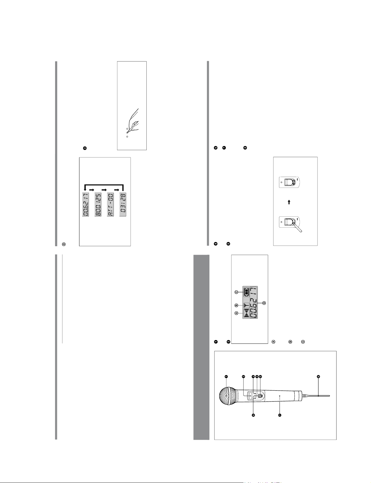
Parts Identification....................................................4
Power Supply ............................................................ 7
Settings ......................................................................8
Initiating Setting Mode .....................................8
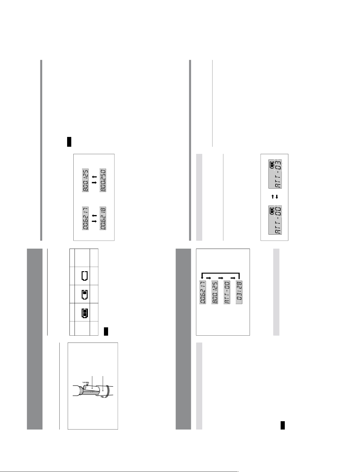
Changing the Transmitting Channel .................8
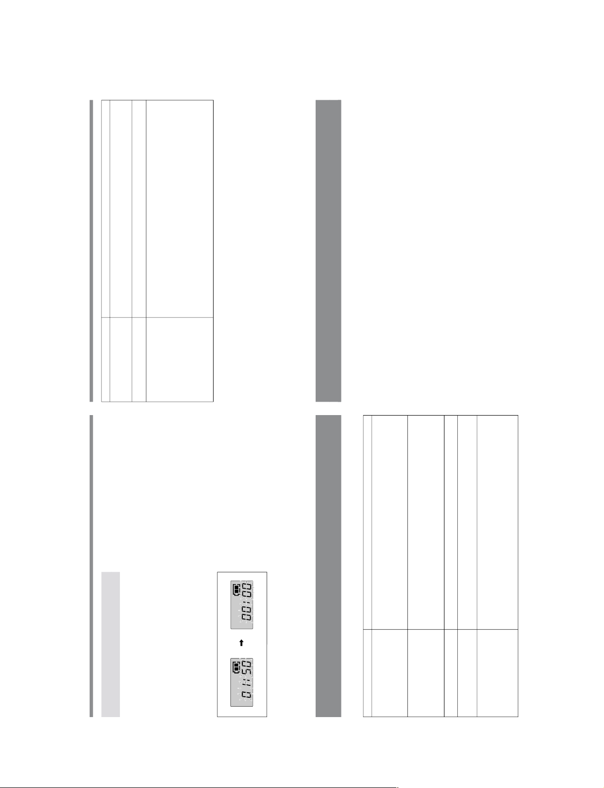
Changing the Input Attenuation Setting ..........10
Resetting the Accumulated Battery Use Time
Indication ...................................................11
Troubleshooting ......................................................12
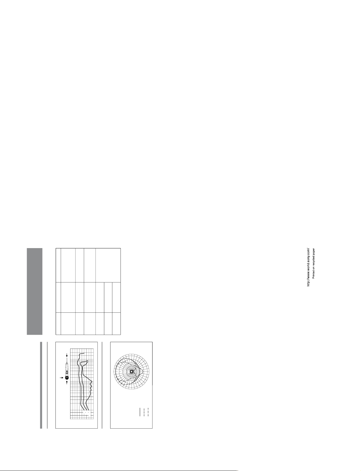
Specifications..........................................................14
Error Messages ....................................................... 15
2
(GB)
Introduction
The WRT-807B is a UHF-synthesized wireless microphone
for use in a 800-MHz band UHF-synthesized wireless
microphone system.
The WRT-807B operates in conjunction with the MB-806A
with WRU-806B UHF Synthesized Tuner Unit for vocal
concentration.
The WRT-807B can be also used with existing Sony
wireless microphone systems consisting of the WRT-805B/
855B UHF Synthesized Transmitter and WRR-805B/855B/
862B UHF Synthesized Tuner, etc.
Transmitting Channel Band
The microphone/transmitter and tuners of wireless
microphone systems are classified by frequency band.
A 24-MHz frequency band is assigned to each microphone/
transmitter and tuner model.
In building a UHF wireless microphone system, be sure to
pair a microphone/transmitter with a tuner that has the same
TV channel number.
Features
Phase Locked Loop (PLL) synthesized system
The WRT-807B features a refined phase locked loop (PLL)
synthesizer circuit.
POWER switch with holding function
The POWER switch can be locked in the ON position to
protect against accidental power cut-offs.
Low-battery notification on tuner
When the microphone battery is low, the microphone sends a
warning to the WRR-805B/862B/WRU-806B in the form of
“Battery status information.”
This information is sent to the WRR-805B/862B/WRU-
806B about one hour before the battery goes dead to allow
the battery to be safely replaced.
When the WRR-805B/862B/WRU-806B receives this
information, the LED on tuner panel starts to flash.
Powered by readily available battery type
The built-in, high-efficiency DC-DC converter provides
about
single5 hours of continuous and stable operation with just a
LR6 (size-AA) alkaline battery.

1-3
WRT-807B (U/CE)
5
(GB)
+
SET
–
Display example
for CE62 model
CH (channel) indication
Displays the transmitting channel.
Each time you press the SET button in Transmit mode, the
channel indication changes as follows.
Transmitting channel: The current transmitting channel
setting.
Transmitting frequency: The current transmitting
frequency setting.
Attenuation: The input attenuation setting in decibels.
Can be set within a range of 0 dB to 21 dB in 3-dB
steps.
Accumulated battery use time: The accumulated time of
battery use (in 1-minute increments).
Transmitting
channel
To adjust these parameters, see “Changing the transmitting
Channel” on page 8, “Changing the Input Attenuation
Setting” on page 10 or “Resetting the Accumulated Battery
Use Time Indication” on page 11.
SET button
In Transmit mode, press this button to change the indicated
items in the lower half of the liquid-crystal display.
To change to Setting mode, turn the POWER switch to ON
while holding this button down. Then press this button to
select the items to be indicated.
How to press the SET and +/–buttons
For details on Setting mode, see “Settings” on page 8.
Press the button with a
ballpoint pen or similar item.
Transmitting
frequency
Attenuation level
Accumulated
battery
Press use time
SET button.
6
(GB)
ON
HOLD
ON
HOLD
POWER indicator
Lights when the microphone is on.
POWER switch
Turns the microphone ON or OFF.
When you set this switch to ON without holding down any
other button, the microphone enters Transmit mode, and the
signal of the selected channel is transmitted.
The HOLD switch appears when the POWER switch is set
to ON.
Set the HOLD switch to the lock position to prevent an
accidental power cut-off during microphone operation.
Locking the POWER switch
Slide the HOLD switch to the
right with a ballpoint pen or
similar item.
Antenna
Battery holder
Insert the battery here.
For details on inserting the battery, see “Power Supply”on
page 7.
+ (+ selection) / – (– selection/reset) buttons
In Setting mode, use these buttons to select the transmitting
channel and attenuation level, and use the –button to reset
the accumulated battery use time indication to 00:00.
For details on Setting mode, see “Settings”on page 8.
A yellow mark appears
when the switch is in the
hold position.
Parts Identification
4
(GB)
Display example
for CE62 model
Parts Identification
Wind screen
Protects against noise caused by wind.
Liquid-crystal display
AF (audio input) indication
Lights whenever an audio signal stronger than the reference
level is received.
RF (antenna output) indication
Lights during signal transmission from the antenna.
BATT (battery) indication
Shows
See the battery condition.
“Battery indication”on page 7.
AF RF BATT
3
(GB)
LCD readout of various information
The microphones LCD shows the current channel number,
frequency, input attenuation setting, and residual battery
power.
The accumulated battery use time is also indicated (in one-
minute increments) to allow precise monitoring of battery
use.
Automatic saving of channel and input attenuation
settings
All channel and input attenuation settings are automatically
saved when the microphone is turned off (and are
maintained even when the battery is removed), thus
eliminating the need to make the same settings again the
next time you use the microphone.
Highly reliable electronic attenuator
Adjustable in a range of 0 dB to 21 dB in 3-dB steps, the
built-in input level attenuator reduces signal distortion
during the input of excessively strong audio signals.
Tone signal-incorporated RF carrier signal
The microphone transmits an RF carrier signal that
incorporates a tone signal to enable any tuner with a tone
squelch circuit to pick out only the target audio signal.
Wide dynamic range and low noise
The microphones compander (compressor/expander) system
enables transmission over a wide dynamic range with
minimum noise.
Notes on operation
•When operating two or more microphones, keep the
microphones separated from each other by a distance of at
least 30 cm (1 foot).
•Keep
the microphones at least 3 meters (10 feet) away from
receiving antenna.

1-4 WRT-807B (U/CE)
7
(GB)
1234
BATT
indication
Lights Lights Flashes Goes off
Battery
condition Good Less than
half-charge Almost
exhausted Completely
exhausted
2
1,3
E
e
Power Supply
The microphone can operate on one LR6 (size AA) alkaline
battery continuously for about 5 hours at 25 ºC (77ºF).
Inserting the battery
1
Turn the grip in the direction of the arrow to open the
battery holder.
2
Match the battery to the polarity markings and insert it
into the battery holder.
3
Close the battery holder and lock the grip by turning it
in the opposite direction of the arrow.
Battery indication
When you turn the power on, the battery condition is
indicated by the BATT indication in the liquid-crystal
display.
Note
The indication may be incorrect if the battery was not new
when inserted. If you plan to use the microphone for a long
period, replace the battery with a new one.
8
(GB)
Channel selection
mode
*
Freqency selection
mode
Attenuator adjustment
mode
Accumulated time
indication reset mode
Press the
SET button.
Display example
for CE62 model
Settings
Initiating Setting Mode
Enter Setting mode to change the transmitting channel, the
transmitting frequency and the attenuation level, or to reset
the accumulated battery use time indication.
To enter Setting mode
While holding down the SET button, turn the POWER
switch to ON.
Hold the SET button down until an indication appears on the
liquid-crystal display.
The microphone enters Setting mode and the indication
before the microphone was previously turned OFF flashes
on the liquid-crystal display.
Pressing the SET button cycles the modes in the order of
Channel selection mode, Frequency selection mode (page
9), Attenuator adjustment mode (page 10) and Accumulated
time indication reset mode (see page 11).
Note
On the model available in Europe, the transmitting channels
are grouped in four sets as shown in “Sony Wireless
Microphone System Frequency List.”
* On the model available in Europe, set the channel group indication (the
left two digits) first. Press the + or –button to toggle the channel
group (e.g., for CE62 model: 00 y62 y63 y64) and press the
SET button. Then, the remaining four digits start to flash for setting
the channel number.
Changing the Transmitting Channel
The transmitting channel can be selected through either the
channel number or the frequency.
1Set the microphone to Setting mode.
If the channel number (or frequency) indication does not
appear,
(or press the SET button until the channel number
frequency) indication appears.
9
(GB)
Channel selection mode Freqency selection mode
+ button –button + button –button
Display example for CE62 model
2
Press the + or –button to select the channel number (or
frequency).
Pressing the + button cycles the indication in the order
shown in separate “Sony Wireless Microphone System
Frequency List.”Pressing the –button cycles the
indications in the opposite direction.
Hold down the button to change the channel number (or
frequency) quickly.
3
When the desired channel number (or frequency)
appears, turn the POWER switch to OFF to release
Setting mode, or press the SET button to continue
operations in Setting mode.
The next time you turn on the microphone (by turning the
POWER switch to ON), the microphone will enter Transmit
mode with the selected channel number (or frequency).
Notes
•The microphone cannot transmit in Setting mode.
•Make sure that the channel selected on the microphone is
the same as that selected on the tuner being used in the
same system.
•Depending on the noise or interference conditions, all
selectable channels may not be usable. If necessary, you
can determine which channels are usable by cycling the
channel selection through a number of channels on the
tuner with the microphone set to OFF. Those channels for
which the RF indicator on the tuner does not light are
usable.
•The microphone may not operate correctly if it is turned
on immediately after being turned off in Setting mode.
Wait for a few
Wait for a few seconds before turning the power on again.
10
(GB)
+ button
AF RF BATT AF RF BATT
–button
Changing the Input Attenuation Setting
The input attenuation setting can be changed within a range
of 0 dB to 21 dB (in 3-dB steps) in either Setting mode or
Transmit mode.
Changing the input attenuation in Setting
mode
1Set the microphone to Setting mode.
2If the attenuation level is not displayed, press the SET
button until it appears.
3Press the + or –button to change the attenuation setting.
Hold down the button to change the level quickly.
4Once the desired level appears, turn the POWER switch
to OFF to release Setting mode, or press the SET button
to continue operations in Setting mode.
The next time you turn on the microphone (by turning the
POWER switch to ON), the microphone enter Transmit
mode with the selected attenuation setting.
Changing the input attenuation in Transmit
mode
You can also change the input attenuation setting while
transmitting
If
button
in Transmit mode.
1the attenuation level is not displayed, press the SET
until it appears.
2Press the + or –button to change the attenuation setting.
Setting

1-5
WRT-807B (U/CE)
11
(GB)
AF RF BATT AF RF BATT
–button
Resetting the Accumulated Battery Use
Time Indication
The accumulated battery use time is the total time (in hours
and minutes) the battery has been used. It is recorded
whenever the WRT-807B is on.
Reset the indication to 00:00 whenever you replace the
battery.
1Set the microphone to Setting mode.
2If
4Turn
the accumulated battery use time is not displayed,
press the SET button until it appears.
3Press the –button.
The indication resets to 00:00.
Press the + button while the 00:00 indication is on to go
back to previous value.
the POWER switch to OFF to release Setting
mode.
12
(GB)
Troubleshooting
If you have any problem using this unit, use the following checklist. Should any problem persist, consult your Sony dealer.
Symptom Meaning/Remedy
The microphone does not turn on. •The + and –poles of the battery do not match those of the battery compartment. bInsert the
battery with the poles correctly matched.
•The battery is exhausted. bReplace the battery with new one.
•The battery terminals in the microphone are dirty. bClean the + and –terminals with a cotton
swab.
The battery runs down quickly. •The battery is exhausted. bReplace the battery with new one.
•A manganese battery is being used. bUse an alkaline battery. The battery life of a manganese
battery is less than half that of an alkaline battery.
•The microphone is being used under cold conditions. bThe battery runs down quickly under cold
The microphone cannot be turned
off. The HOLD switch is in locked position. bChange the HOLD switch to the unlocked position.
The channel cannot be changed. An attempt was made to change the channel by pressing the SET button only. bTurn the
microphone
conditions.
off, then turn the microphone on again while holding down the SET button. Then
change the channel with the + and –buttons.
There is no sound. •The indication on the LCD is flashing. bThe
b
microphone is in channel setting mode. Turn the
power off, then on again.
•The channel setting on the microphone is different from that on the tuner. bUse the same channel
setting for both the microphone and tuner.
•The AF or RF indicator does not turn on. Confirm that the microphone and tuner are both turned
on.
13
(GB)
The sound is weak. •The attenuation level setting is too high. bThe output level is low. Press the –button in attenuation
level setting mode to lower the attenuation level.
•The volume on the amplifier, mixer or tuner is low. bAdjust the volume.
There is distortion in the sound. The attenuation level setting is too low. bThe input level is extremely high. Press the + button in
attenuation level setting mode to raise the attenuation level.
There is sound interruption or
noise. •The receiver's antenna is incorrectly connected. bConnect the antenna correctly according to the
operation manual of the tuner or antenna divider.
•The antenna divider is turned off. bTurn the antenna divider on. It is possible for the tuner to
receive signals even when the antenna divider is turned off, but sound interruption or noise may
occur.
•The RF indicator lights even when the microphone is off. bJammed transmissions are being
received. Determine which channels are usable (i.e., channels for which the RF indicator on the
tuner
Two
the
does not light) and set the tuner and microphone to the same usable channel.
•or more microphones are set to the same channel. bMake sure no two microphones are set to
same channel. Set each microphone to a different channel.
Symptom Meaning/Remedy
14
(GB)
. . . . . . . . . . . . . . . . . . . . . . . . . . . . . . . . . . . . . . . . . . . . . . . . . . . . . . . . . . . . . . . . . . . . . . . . . . . . . . . . . . . . . . . . . . . . . . . . . . . . . . . . . . . . . . . . . . . . . . . . . . . . . . .
1) 0 dB
SPL
= 2 x10
-5
Pa
Specifications
Power section
Power requirements 1.5 V DC
(one LR6/size AA alkaline
battery)
Battery life Approx. 5 hours at 25°C or
77°F, with Sony LR6 alkaline
battery
General
Operating temperature 0°C to +50°C (32°F to 122°F)
Storage temperature –30°C to +60°C (–22°F to
+140°F)
Dimensions 51 x238 mm (diameter/length)
not including antenna
(2-1/8 x9-3/8 inches)
Mass Approx. 440 g (15.5 oz)
including battery
Supplied accessory
Operating Instructions (1)
Sony Wireless Microphone System Frequency List (1)
Microphone holder (1)
Stand adaptor (PF
1
/
2
to W
3
/
8
) (for CE57/62/67 model) (1)
Stand adaptor (PF
1
/
2
to NS
5
/
8
) (for U62/66 model) (1)
Channel color seal (1)
Design and specifications are subject to change without
notice.
Transmitter and modulator section
Oscillator Crystal controlled PLL
synthesizer
Type of emission F3E
Carrier frequencies
CE57 model: 758.025 to 782.000 MHz
CE62 model: 798.025 to 822.000 MHz
CE67 model: 838.025 to 862.000 MHz
U62 model: 758.125 to 781.875 MHz
U66 model: 782.125 to 805.875 MHz
RF power output 10 mW (50-ohm load)
Tone signal 32.768 kHz
Battery condition signal 32.782 kHz
Type of antenna 1/4 -wavelength wire
Audio section
Microphone type uni-directional dynamic
microphone
Pre-emphasis 50 µs
Deviation ±5 kHz (94 dB
SPL1)
, 1 kHz input)
Frequency response 50 to 15,000 Hz
Signal-to-noise ratio 57 dB or more (A-weighted,
modulation frequency 1 kHz,
with ±5 kHz deviation at WRU-
806B with MB-806A)
Audio attenuator 0 to 21 dB, variable in 3-dB
steps
Input level 151
(at dB
SPL
audio attenuator 21 dB)

1-6 WRT-807B (U/CE)
15
(GB)
Standard frequency response
Standard directivity response
Error Messages
When a problem occurs, one of the following error
messages may appear on the display.
20
dB
10
0
–10
–20
–30 20 50 100 200 500 1k 2k 5k 10k 20k Hz
0d
90d
180d
0d180d
90d
100 Hz
1 kHz
6 kHz
0
d
30
d
30
d
60
d
60
d
90
d
90
d
120
d
120
d
150
d
150
d
180
d
0dB
–5
–10
–15
–20
Message Contents Measures
Error 11 An error occurred in
backup memory data. The data was initialized.
Set the transmitting
channel and the input
attenuation again.
Error 21 The PLL synthesized
circuit is in trouble. Contact your Sony
dealer.
Error 31 The battery voltage
exceeds the allowable
value.
Use the specified battery.
Error 41 Defect of an internal
circuit.
Error 51 Defect of the A/D
converter circuit.
Error 61 Defect of an internal
circuit.
Contact your Sony
dealer.
Specifications
Sony Corporation
Printed in Japan

2-1
WRT-807B (U/CE)
Section 2
Service Overview
2-1. Disassembly
Cage assembly
DM unit assembly
Cage assembly
Don't touch here when removing.
DM unit
assembly
Sub harness (MIC)
Sub harness (MIC)
Tweezers
Do not press the connector of the DM unit.
(To prevent the possibility of solder crack.)
Stop ring removal tool
Grip B
Stop ring removal tool
Grip B
Grip B
Ring
*
Stop ring
Push the hooks on the stop ring
with the stop ring removal tool
and remove grip B.
*Tool required
.Stop ring removal tool
(Sony part No. : J-6402-510-A)
Grip B
to page 2-2
to 2-2
page

2-2 WRT-807B (U/CE)
Antenna
Switch cover, Switch assembly, Grip A
Antenna
O ring, P15
Antenna
Hex. set-screw (2 x 4)
*
*Tool required
.Hex. head screwdriver
(Sony part No.: 7-700-766-01)
LCD plate
Tweezers
Grip A Grip A
Grip A
LRT type (M 2 x 4)
Unit assembly
Switch
LRT type
(M 2 x 4)
Ring
Switch assembly
Switch cover
*Tool required
.LRT driver
(Sony part No.: J-6402-350-A)
*
*

2-3
WRT-807B (U/CE)
WRT-807A (CE, AU)
Chassis A, Chassis B, CN-1868 board, DP-306 board, MB-860 board
DP-306 board
Chassis A
MB-860 board
MB-860 board
CN-1868 board
Sub harness (MIC)
Chassis A
Chassis A
Chassis A
Chassis B
2
1
3
4
+
_
LugGround plate
MB-860 board
Unsolder.
Battery spring
Remove the board
from the claws. Remove the DP-306 board
in the order of 1, 2, 3and 4.

2-4 WRT-807B (U/CE)
2-2. Note On Parts Replacement and
Reassembly
2-2-1. Precautions on Reassembly
1. DM unit assembly
2. Stop ring
3. DP-306 board
4. MB-860 board
5. Battery spring
DM unit assembly
After turning the DM unit assembly
three turn in the direction of the
arrow, attach it to the grip A.
Grip A
Grip B
Stop ring
Be sure to mount the stop ring in the prescribed direction.
Chassis A
DP-306 board
When attaching the DP-306 board to the chassis A,
insert the DP-306 board in the order of 1and 2
in the direction of the arrow as shown, and attach
the DP-306 board inside the 2 claws.
1
2
Chassis A
DP-306 board
Claw
Chassis A
MB-860 board
1
Chassis A
MB-860 board
2
When attaching the MB-860 board to the chassis A,
insert the MB-860 board in the order of 1and 2in
the direction of the arrow as shown.
MB-860 board
DP-306 board
Connector (CN200)
Connector (CN304)
Insert only the first-turn
of battery spring.
Battery spring

2-5
WRT-807B (U/CE)
2-2-2. Note on Parts Replacement
.EEPROM (IC202, DP-306 board) replacement
When replacing EEPROM (IC202) on the DP-306 board
or replacing DP-306 board, perform the following
operation.
When the power is turned on initially after the replace-
ment:
1. “Error 11” is indicated on the display.
2. Turn off the power. Next turn on the power again.
Confirm that “CE57B” (for CE57 model) is indicated
on the display.
Confirm that “CE62B” (for CE62 model) is indicated
on the display.
Confirm that “CE67B” (for CE67 model) is indicated
on the display.
Confirm that “U30B” (for U30 model) is indicated on
the display.
Confirm that “U42B” (for U42 model) is indicated on
the display.
Confirm that “U62B” (for U62 model) is indicated on
the display.
Confirm that “U66B” (for U66 model) is indicated on
the display.
2-3. Unleaded Solder
Boards requiring use of unleaded solder are printed with a
lead free mark (LF) indicating the solder contains no lead.
(Caution: Some printed circuit boards may not come
printed with the lead free mark due to their particular size.)
: LEAD FREE MARK
m
.Be sure to use the unleaded solder for the printed circuit
board printed with the lead free mark.
.The unleaded solder melts at a temperature about 40 dC
higher than the ordinary solder, therefore, it is recom-
mended to use the soldering iron having a temperature
regulator.
.The ordinary soldering iron can be used but the iron tip
has to be applied to the solder joint for a slightly longer
time. The printed pattern (copper foil) may peel away if
the heated tip is applied for too long, so be careful.


3-1
WRT-807B (U/CE)
Section 3
Electrical Alignment
3-1. Equipment and Tools
Equipment Required
Name Specifications Model Name
DC Power Supply Output regulated voltage : 0 to 5 Vdc, 2 A _
DC Ammeter Measurement range : 300 mA _
Spectrum Analyzer Frequency : 10 kHz to 4 GHz ADVANTEST R3371B or equivalent
Modulation Analyzer RF input Frequency : 150 kHz to 3 GHz ANRITSU MS616A or equivalent
RF Power Meter Range : 3 uW to 100 mW HEWLETT PACKARD 435B (with Power sensor HEWLETT
with Power sensor PACKARD 8482A) or equivalent
Audio Analyzer Oscillator : 20 Hz to 100 kHz HEWLETT PACKARD 8903B (with A-weighted filter) or equivalent
Distortion meter
S/N meter
Level meter
Frequency Counter Frequency : 10 Hz to 1000 MHz HEWLETT PACKARD 5385A or equivalent
Effective digits : 10 digits
Resolution : 0.1 Hz
Oscilloscope Frequency : DC to 10 MHz _
1
Digital Volt Meter Effective digit : 3 / digits _
2
Tools Required
Name Part No. Remarks
SMA-BNC (J) connector J-6402-490-A For RF signal input
RF conversion connector J-6402-400-A For RF signal input
AF input cable _For AF signal input
Refer to the “How to make a AF input cable”.
Adjustor (0.4 x1.3 mm) 7-721-052-81
LRT driver J-6402-350-A For Grip A removal
How to make a AF input cable
Required parts
AF input connector ;1 (Part No. J-6402-470-A)
Cable with BNC connector ; 1 (Part No.1-555-758-00)
1 pin (black) 2 pin (white)
Solder.
Shield
3 pin (orange)
Cable with BNC connector
AF input connector (female)

3-2 WRT-807B (U/CE)
3-2. Adjustments
This section describes the following adjustments and checks
required to satisfy specifications.
Adjustment and Check Items
3-2-1. Power Supply Voltage Check
3-2-2. Carrier Frequency Adjustment
3-2-3. RF Power Output Adjustment
3-2-4. Reference Frequency Deviation Adjustment
3-2-5. Maximum Frequency Deviation Adjustment
3-2-6. Distortion Ratio Check
3-2-7. S/N Check
3-2-8. Frequency Characteristics Check
3-2-9. Tone Signal Adjustment
3-2-10.Battery Alarm Signal Check
3-2-11.Spurious Emissions Check
Preparation
1. Remove the MB-860 board, DP-306 board and CN-
1868 board from WRT-807B unit, and then the MB-
860, DP-306 and CN-1868 boards must be connected
electrically as shown below.
Refer to the “Section 2. Service Overview “ for removal.
2. Connect the SMA-BNC (J) connector (J-6402-490-A)
with RF conversion connector (J-6402-400-A) to the
antenna connector (CN305) on the MB-860 board as
shown below.
3. Connecting the DC power supply
Supply the DC power to the battery terminals on the
MB-860 board as shown below.
Check
After the DC power supply connection is completed, set
the power switch (S101) to ON, and check the level on DC
ammeter.
DC ammeter indication level : 150 to 175 mA
GND
VCC
MB-860 board (B side)
DC power supply DC ammeter
++_
_
Lead wire
Solder.
CN200
CN304
CN-1868 board
DP-306 board
MB-860 board
RF conversion
connector
CN305
(B side)
1.5 ±0.1 V dc
SMA-BNC (J) connector

3-3
WRT-807B (U/CE)
Switch and Control Initial Setting
The following initial setting is to be perform with the SET
switch (S202), “+”switch (S200) and “_”switch (S201).
Transmitting Channel setting:
CE57 model ; Group 00, 58-32 channel (770.000 MHz)
CE62 model ; Group 00, 63-32 channel (810.000 MHz)
CE67 model ; Group 00, 68-32 channel (850.000 MHz)
U30 model ; 32-01 channel (578.125 MHz)
U42 model ; 44-01 channel (650.125 MHz)
U62 model ; 64-01 channel (770.125 MHz)
U66 model ; 68-01 channel (794.125 MHz)
Attenuation setting : 0 dB
Accumulated time setting : “00 : 00”
Adjustment Location
3-2-1. Power Supply Voltage Check
Equipment and Tools Required
DC power supply
DC output voltage : +1.5 ±0.1 Vdc
DC ammeter
DC volt meter (or Digital multimeter)
Adjuster (Part No. 7-721-052-81)
Switch and Control Setting
Same as “Switch and Control Initial Setting”on page 3-3.
Procedure
(1) Set the POWER switch (S101) on the MB-860 board to
ON.
(2) Check the DC Voltage of the L102 terminal to the spec-
ified voltage as below :
Specification : DC Voltage at L102 terminal
= +3.0 ±0.1 Vdc
(3) Check the DC voltage of the L101 terminal to the spec-
ified voltage as below :
Specification : DC voltage at L101 terminal
= +5.0 ±0.1 Vdc
VCC RV301
S200
(+)
CT200
S101
(POWER)
RV302
S201 (_)
S202 (SET)
ON
GND
CT301
CN305
RV305
RV304
RV303
CN-1868 board
DP-306 board
MB-860 board (B side) MB-860 board (A side)
C376
R366
C369
R401
L102
C108
L101
T101 T102
C109
C107
C117
C102
C101
R117
C364
C366
C383C384
R108
C386
IC101IC102
C334
L102
P301
R395
Frequency counter
+
_
MB-860 board (B side)
L101
GND
L102

3-4 WRT-807B (U/CE)
3-2-2. Carrier Frequency Adjustment
Equipment and Tools
DC power supply
DC output voltage : +1.5 ±0.1 Vdc
DC ammeter
Frequency counter
SMA-BNC (J) connector (Part No. J-6402-490-A)
RF conversion connector (Part No. J-6402-400-A)
Adjustor (Part No. 7-721-052-81)
Connections
(For connecting the DC power supply, refer to the
“Preparation”on page 3-2.)
Switch and Control Setting
Same as “Switch and Control Initial Setting”on page 3-3.
Procedure
(1) Connect the frequency counter to the antenna connector
(CN305) with SMA-BNC (J) connector (and RF con-
version connector).
(2)
Adjust 1CT200 on the DP-306 board so that the frequency
counter reading meets the following specification.
Specification :
Carrier frequency mentioned in the table
below.
WRT-807B Carrier frequency
CE57 model 770.000 MHz ±1 kHz
CE62 model 810.000 MHz ±1 kHz
CE67 model 850.000 MHz ±1 kHz
U30 model 578.125 MHz ±1 kHz
U42 model 650.125 MHz ±1 kHz
U62 model 770.125 MHz ±1 kHz
U66 model 794.125 MHz ±1 kHz
Adjustment :1CT200/DP-306 Board (A side)
3-2-3. RF Power Output Adjustment
Equipment and Tools
DC power supply
DC output voltage : +1.5 ±0.1 Vdc
DC ammeter
Power meter (with power sensor)
SMA-BNC (J) connector (Part No. J-6402-490-A)
RF conversion connector (Part No. J-6402-400-A)
Adjustor (Part No. 7-721-052-81)
Connections
(For connecting the DC power supply, refer to the
“Preparation”on page 3-2.)
Switch and Control Setting
Same as “Switch and Control Initial Setting”on page 3-3.
Procedure
(1) Connect the power meter (with power sensor) to the
antenna connector (CN305) with SMA-BNC (J)
connector (and RF conversion connector).
(2) Adjustment
Specification : Power meter = Maximum
Adjustment :1CT301/MB-860 Board (B side)
(3) Adjustment
Specification : Power meter = +9.0 ±0.1 mW
Adjustment :1RV305/MB-860 Board (B side)
Frequency counter
MB-860 board (B side)
CN305
SMA-BNC (J) connector with
RF conversion connector
Power meter
Power sensor
MB-860 board (B side)
RV305
CT301
SMA-BNC (J) connector with RF conversion connector
Other manuals for WRT-807B
1
Table of contents
Other Sony Microphone manuals

Sony
Sony UTX-B03 User manual

Sony
Sony ECM S80 User manual

Sony
Sony ECM-TL3 User manual

Sony
Sony ECM CG1 User manual

Sony
Sony ECM-330 User manual

Sony
Sony DWM-02 User manual

Sony
Sony Camcorder / Wireless Microphone User manual

Sony
Sony F-V310 User manual

Sony
Sony ECM-AW3 User manual

Sony
Sony ECM-Z70 User manual

Sony
Sony ECM 719 User manual

Sony
Sony ECM-DM5P User manual

Sony
Sony ECMMS907 - Stereo Type Mic User manual

Sony
Sony C-55FET User manual

Sony
Sony ECM-TS125 User manual

Sony
Sony ECM-957PRO User manual

Sony
Sony ECM-969 User manual

Sony
Sony WRT-800A User manual

Sony
Sony ECM-CR120 User manual

Sony
Sony ECM680S User manual