Sony DPP-MS300E User manual

SERVICE MANUAL
DIGITAL PHOTO PRINTER
AEP Model
UK Model
SPECIFICATIONS
DPP-MS300E
9-928-127-31
– Continued on next page –

– 2 –
Flexible Circuit Board Repairing
• Keep the temperature of the soldering iron around 270 ˚C dur-
ing repairing.
• Do not touch the soldering iron on the same conductor of the
circuit board (within 3 times).
• Be careful not to apply force on the conductor when soldering
or unsoldering.
Notes on chip component replacement
• Never reuse a disconnected chip component.
• Notice that the minus side of a tantalum capacitor may be dam-
aged by heat.
ADVARSEL
Eksplosjonsfare ved feilaktig skifte av batteri.
Benytt samme batteritype eller en tilsvarende type
anbefalt av apparatfabrikanten.
Brukte batterier kasseres i henhold til fabrikantens
instruksjoner.
VARNING
Explosionsfara vid felaktigt batteribyte.
Använd samma batterityp eller en likvärdig typ som
rekommenderas av apparattillverkaren.
Kassera använt batteri enligt gällande föreskrifter.
VAROITUS
Paristo voi räjähtää, jos se on virheellisesti asennettu.
Vaihda paristo ainoastaan laitevalmistajan suosittelemaan tyyppiin.
Hävitä käytetty paristo valmistajan ohjeiden mukaisesti.
ADVARSEL!
Lithiumbatteri-Eksplosionsfare ved fejlagtig håndtering.
Udskiftning må kun ske med batteri
af samme fabrikat og type.
Levér det brugte batteri tilbage til leverandøren.
CAUTION
Danger of explosion if battery is incorrectly replaced.
Replace only with the same or equivalent type recommended by
the manufacturer.
Discard used batteries according to the manufacturer’s instructions.
SAFETY-RELATED COMPONENT WARNING!!
COMPONENTS IDENTIFIED BY MARK !OR DOTTED
LINE WITH MARK !ON THE SCHEMATIC DIAGRAMS
AND IN THE PARTS LIST ARE CRITICAL TO SAFE
OPERATION. REPLACE THESE COMPONENTS WITH
SONY PARTS WHOSE PART NUMBERS APPEAR AS
SHOWN IN THIS MANUAL OR IN SUPPLEMENTS PUB-
LISHED BY SONY.

– 3 –
TABLE OF CONTENTS
1. GENERAL
Identifying the parts ..................................................... 1-1
Setting Up .................................................................... 1-1
Printing ......................................................................... 1-4
Making Various Prints.................................................. 1-6
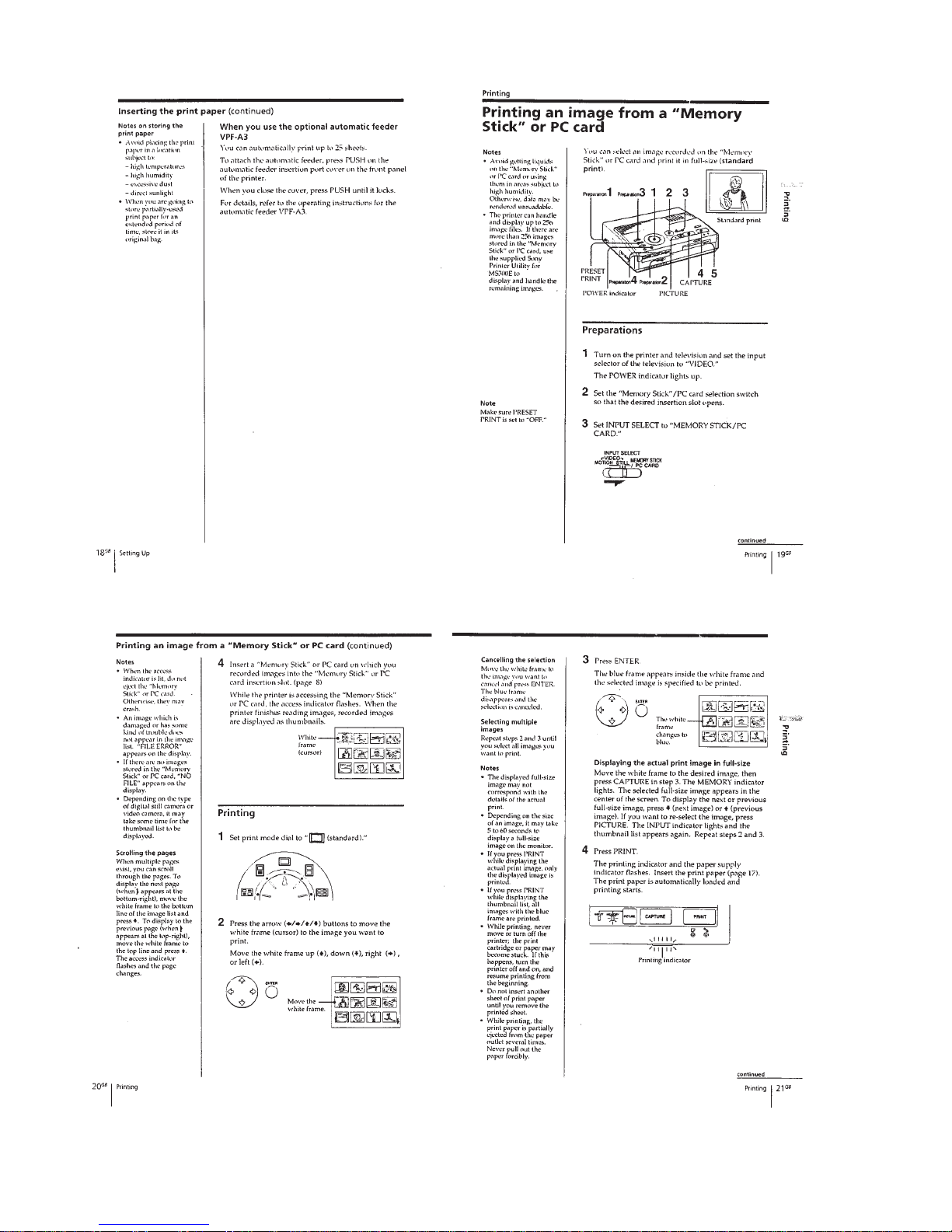
About “Memory Stick” ................................................ 1-10
About PC Cards ........................................................... 1-10
2. DISASSEMBLY ...................................................... 2-1
3. MECHANICAL ADJUSTMENTS.................... 3-1
4. ELECTRICAL ADJUSTMENTS...................... 4-1
Power Supply Block .................................................... 4-3
Video Block.................................................................. 4-4
5. DIAGRAMS
5-1. Block Diagram – VIDEO Section – ........................... 5-1
5-2. Block Diagram – MAIN Section – .............................. 5-3
5-3. Block Diagram – CENTRONICS Section – .............. 5-5
5-4. Block Diagram
– PC CARD/MEMORY STICK Section –................. 5-7
5-5. Block Diagram
– HEAD/SENSOR/MOTOR/
POWER SUPPLY Section – ........................................ 5-9
5-6. Frame Schematic Diagram .......................................... 5-11
5-7. Notes for Printed Wiring Board and
Schematic Diagram...................................................... 5-13
5-8. Printed Wiring Board – VS-40 Board – ..................... 5-15
5-9. Schematic Diagram – VS-40 Board – ......................... 5-16
5-10. Printed Wiring Board – VI-40 Board – ....................... 5-17
5-11. Schematic Diagram – VI-40 Board – .......................... 5-19
5-12. Printed Wiring Board – DK-40 Board –..................... 5-23
5-13. Schematic Diagram – DK-40 Board (1/3) – ............... 5-25
5-14. Schematic Diagram – DK-40 Board (2/3) – ............... 5-28
5-15. Schematic Diagram – DK-40 Board (3/3) – ............... 5-31
5-16. Printed Wiring Board – MP-40 Board –..................... 5-33
5-17. Schematic Diagram – MP-40 Board – ........................ 5-35
5-18. Printed Wiring Boards – FE-40/JK-40 Boards – ....... 5-39
5-19. Schematic Diagram – FE-40/JK-40 Boards –............. 5-41
5-20. Printed Wiring Board – SW-40 Board –..................... 5-43
5-21. Schematic Diagram – SW-40 Board – ........................ 5-45
5-22. Printed Wiring Boards
– HP-40/JD-40/MD-40/RD-40 Boards – .................... 5-47
5-23. Schematic Diagram
– HP-40/JD-40/MD-40/RD-40 Boards – .................... 5-49
5-24. IC Pin Function Description ........................................ 5-59
6. EXPLODED VIEWS............................................. 6-1
7. ELECTRICAL PARTS LIST ............................ 7-1

1-1
SECTION 1
GENERAL This section is extracted from in-
struction manual (3-866-753-11).

1-2

1-3

1-4

1-5

1-6

1-7

1-8

1-9

1-10
1-10 E

2-1
UPPER CABINET ASS’Y
Note: Follow the disassembly procedure in the numerical order given.
SECTION 2
DISASSEMBLY
1
two screws
(BVTP3
×
20)
harness
button reinforcement
1
two screws
(BVTP3
×
20
)
3
FFC (DKSW39)
(CN504)
2
upper cabinet ass’y
2
two screws
(BTP2.6
×
12)
1
connector
(CN1938)
3
DC fan (head fan) (M901)
DC FAN (HEAD FAN) (M901)

2-2
VI-40/JK-40 BOARD SECTION, DC FAN (POWER FAN) (M905)
DK-40 BOARD SECTION
4
two screws
(BV2.6
×
8)
8
JK-40 board section
5
VI-40 board section
7
two cross (with hole) screws
4
screw
(BV2.6
×
8)
2
DC fan (power fan)
(M905)
1
connector
(CN402)
6
flat cable (DKJK40)
(CN701)
3
flat cable (DKVI40)
(CN102)
3
FFC (VIVS39)
(CN101)
1
flat cable (DKMP15)
(CN702)
4
DK-40 board section
2
three screws
(BV2.6
×
8)
1
flat cable (DKMP30)
(CN703)
1
FP-700 flexible board
(CN501)
1
flat cable (ADFE13)
(CN503)
1
flat cable (ADHE13)
(CN502)
3
harness

2-3
MP-40 BOARD SECTION
ESCUTCHEON (60) BLOCK ASS’Y, MECHANISM DECK SECTION
6
harness
(HH-C00-010-BB)
9
four screws
(P2
×
6.5)
1
two screws
(BV2.6
×
8)
3
card panel
4
card select lever
2
MP bracket ass’
y
7
MP shield case
8
MP-40 board
5
two screws
(BV2.6
×
8)
0
PCMCIA ejector
5
core (FPC)
7
machanism deck section
6
two screws
(BV2.6
×
8)
6
two screws
(BV2.6
×
8)
1
two screws
(BV2.6
×
8)
1
two screws
(BV2.6
×
8)
4
flat cable (POHE13)
(CN202)
3
connector
(CN201)
2
escutcheon (60) block ass’y

2-4
HEAD MOTOR BLOCK ASS’Y (HEAD UP/DOWN) (M902)
MD-40 BOARD
3
two screws
(BVTT 2.6
×
6)
4
bridge
5
HM bracket ass’y
6
two screws
(PS 3
×
4)
7
head motor block ass’y (head up/down
)
(M902)
2
connector
(CN1940)
1
two clamps (LOW TYPE)
2
three connectors
(CN1931, 1932, 1935)
1
FP-702 flexible board
(CN1933)
2
connector
(CN1942)
2
two connectors
(CN1940, 1941)
3
screw
(BVTT2.6
×
6)
4
Removal the MD-40 board
to direction of the arrow.
1
FP-703 flexible board
(CN1934)
1
FP-700 flexible board
(CN1936)
2
connector
(CN1938)

DC MOTOR (STEPPING MOTOR) (PLATEN) (M904), REEL MOTOR BLOCK ASS’Y (RIBBON) (M903)
3
two screws
(BVTT2.6
×
6)
2
DC motor (stepping motor)
(platen) (M904)
1
two screws
(BVTT2.6
×
6)
4
motor bracket ass’y section
3
two screws
(BVTT2.6
×
6)
5
two screws
(PS2
×
4)
6
reel motor block ass’y (ribbon) (M903)
2-5 E

3-1 E
SECTION 3
MECHANICAL ADJUSTMENTS
Replacing theThermal Head
1) Before replacing the head, print the stair-step pattern with the
old head (faulty head).
Note 1: Only when the head is not entirely damaged with black or
white lines.
Note 2: To reproduce the stair-step pattern, refer to “Adjusting
Method 1” in “4. Electrical Adjustments”.
2) Remove the upper cabinet. (Refer to “2. Disassembly”.)
3) Remove the flat cables 1(POHE13) and 2(ADHE13) from
the thermal head. (Refer to Fig. 1)
4) Remove the two screws 3(BVTT2.6 ×6) and remove the
harnesses 4and fan holder 5. (Refer to Fig. 1)
5) Remove screw 6, (PS2.6 ×4) and remove the ribbon guide
7. (Refer to Fig. 2)
6) Remove the two screws 8(PSW2.6 ×8) and remove the ther-
mal head 9from the heat sink 0. (Refer to Fig. 2)
Note: Do not remove the screw !™ fixing the heat sink 0and head
arm !¡.
7) Replace the thermal head 9.
Note: Make sure that the silicon grease (white) does not stick onto
the printing screen of the thermal head. If it does, remove with
alcohol.
8) Assemble in the reverse order of steps 2) to 6).
9) Perform “Head Voltage Adjustment” of “4. Electrical Adjust-
ments” (Page 4-3).
3
two screws
(BVTT2.6
×
6)
4
harness
4
harness
2
flat cable
(ADHE13)
1
flat cable
(POHE13)
5
fan holder
!¡
head arm
8
two screws
(PSW2.6
×
8
)
6
screw
(PS2.6
×
4)
7
ribbon guide
!™
two screws
Note: Do not remove
the screw.
0
heat sink
9
thermal head
Fig. 1
Fig. 2

4-1
SECTION 4
ELECTRICAL ADJUSTMENTS
During the adjustment, see the Adjustment and Adjust-
ment Pats on page 4-7.
Pre-Adjustment Preparations
1. Equipment required
Electrical adjustment requires the following measuring equip-
ment.
(1) Monitor TV
(2) Oscilloscope: 2 phenomena, bend 30 MHz or more, with de-
lay mode (use 10 : 1 probe unless otherwise specified)
(3) Frequency counter
(4) Pattern generator
(5) Digital voltmeter
(6) Video print paper
(7) Video print cartridge
(8) Vector scope
2. Connection of Equipment
Following the designation of input terminal (S-VIDEO orVIDEO),
connect measuring units as shown in Fig. 4-1 and make adjust-
ment.
The input terminal is designated with ( ) in the signal column.
Unless otherwise designated, either input terminal may be used.
Note: In the adjustment where the S-VIDEO input is designated, if ad-
justment was made with the VIDEO input. The specification of
this set will not be satisfied. Always follow the designation.
If adjustment was made using theVTR with S-VIDEO OUT termi-
nal as a signal source, the performance of this set depends on that
VTR. Therefore, use the pattern generator with the Y/C separate
output terminals, if possible.
Fig. 4-1
If S-VIDEO is designated
Pattern Generator Pattern Generator
Pattern Generator
VIDEO IN
S-VIDEO
IN
Monitor TV
Set
VIDEO IN
VIDEO
OUT
S-VIDEO OUT
VIDEO OUT
(75
Ω
)
VIDEO OUT
(75
Ω
)
Y OUT (75
Ω
)
Chroma OUT
(75
Ω
)
VTR with S-VIDEO terminal (E-E mode)
•
If pattern generator does not provide Y/C separate
output terminals
•
If pattern generator provide
Y/C separate output terminals
If VIDEO is designated
Other manuals for DPP-MS300E
1
Table of contents
Other Sony Printer manuals

Sony
Sony UP-51MDP User manual

Sony
Sony UP-D2500 User manual

Sony
Sony DPP FP70 - Picture Station Photo Printer User manual

Sony
Sony UP-D75MD User manual

Sony
Sony UP-970AD User manual

Sony
Sony UP-GR700 Guide

Sony
Sony UP-TX1 Series Installation and operation manual

Sony
Sony DPP--SV77 User manual

Sony
Sony DPP-FP50 Fall 2005 User manual

Sony
Sony DMP-1000P User manual