1-6 (E) HKDW-704
1-7. Removing and Reinstalling the DVP
Board Assembly
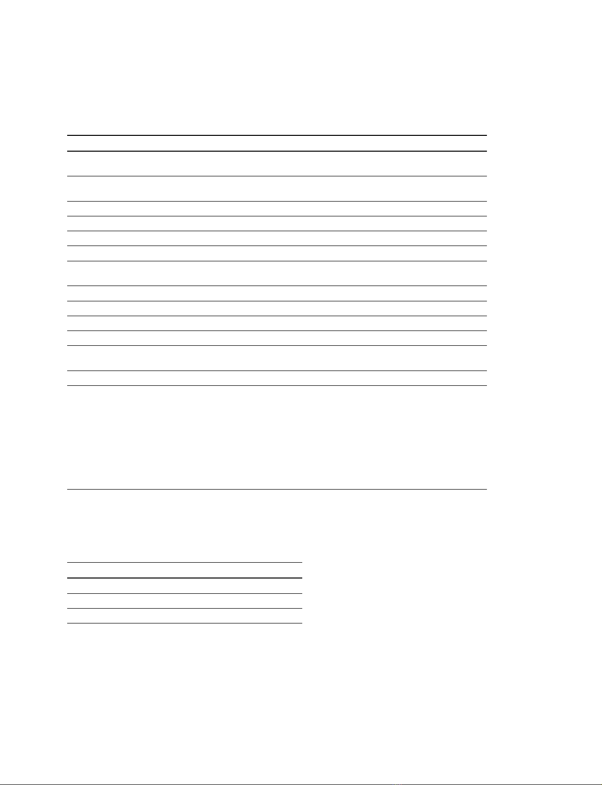
Removal
1. Open the inside panel.
2. Disconnect the DCP board assembly.
3. Disconnect the flexible card wire from the connector
(CN101) on the EQ-88 board.
m
.Life of flexible card wire will be significantly
shortened if it is folded. Be very careful not to fold
the flexible card wire.
.If the copper plating of the base material exposes
due to wear of the tin plated contact of the connec-
tor, replace it with the new flexible card wire.
4. For the HDW-750/750P/750CE/730 only
Disconnect the coaxial cable from the connector
(CN201) on the TX-78 board.
EQ-88 board
TX-78 board
CN201
Coaxial cable (white)
CN101
Flexible card wire
Reinstallation
1. Raise the board lever to its upright position.
2. Insert the DCP board assembly in a slant angle until
the projection of the PC board holder (F) meets the
recess of the DCP board assembly. At the above angle,
raise in the right angle and insert it.
3. When shaft of the board lever enters into the chassis,
slant the board lever and push down the board from its
top until it is firmly inserted to the board-to-board
connector of the MB-898 board.
4. Reinstall it by reversing the steps of disassembling.
n
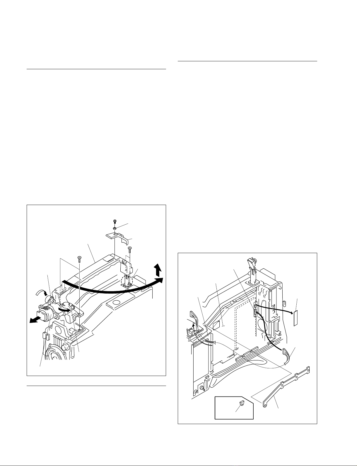
.When re-installing the harness that is disconnected
in step 2, the CNAharness must be hooked on the
top edge of the AT-143 board.
.When re-installing the CNBharness, twist it by 3
turns and install it by pushing in the direction of
arrow A. The CNBharness must be installed 20
mm more far from the CNAharness.
.Fix the harness with the coating lead pin.
Illustlation when viewed
from the top
Illustration when viewed
from the front
Distance of
20 mm or more
DCP-28 board
DCP-28 board
AT-143 board
AT-143 board
DCP-28 board
CNB
A
CNA
CNB
CNA
Harness
Harness
Coating lead pin
1-6. Removing and Reinstalling the DCP Board Assembly
1-7. Removing and Reinstalling the DVP Board Assembly