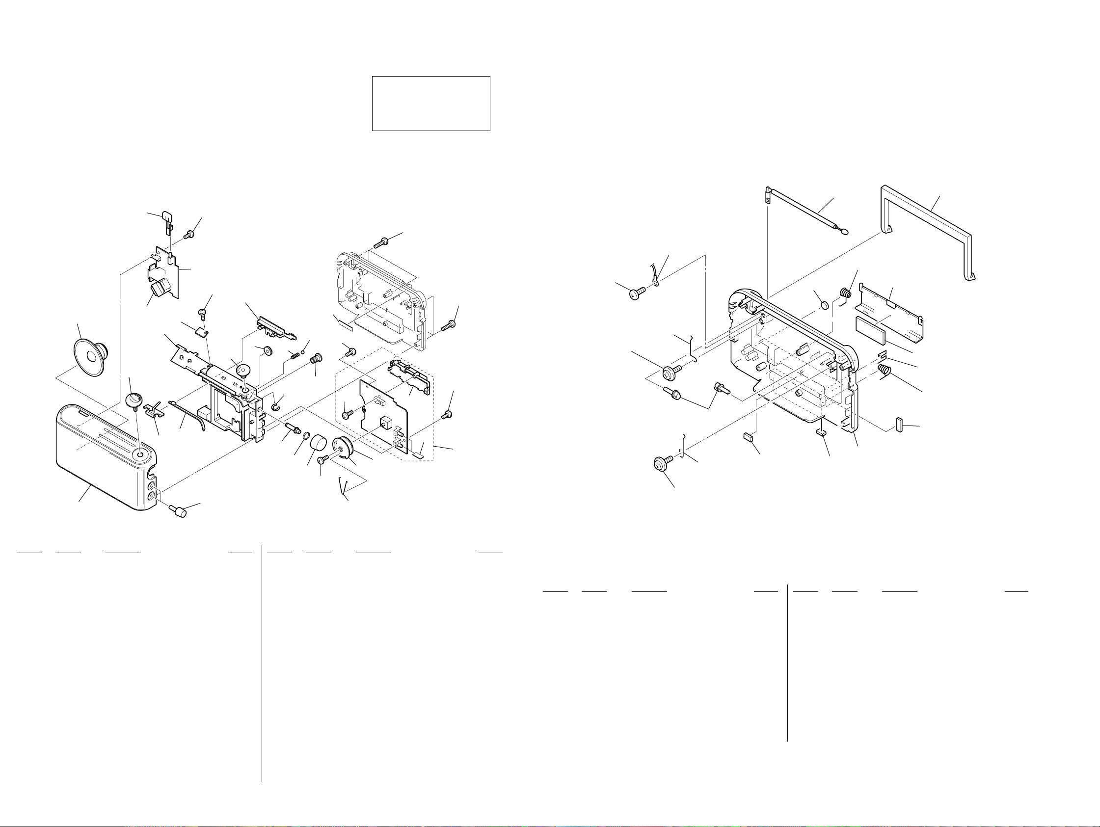
SECTION 5
EXPLODED VIEW
NOTE:
• The mechanical parts with no reference
number in the exploded views are not supplied.
• Items marked “*” are not stocked since
they are seldom required for routine service.
Some delay should be anticipated
when ordering these items.
• Color Indication of Appearance Parts
Example :
KNOB, BALANCE (WHITE) ... (RED)
Parts Color Cabinet’s Color
• Accessories and packing materials are given in
the last of this parts list.
Ref. No. Part No. Description Remark Ref. No. Part No. Description Remark
– 13 – – 14 –
1 X-3379-334-1 CABINET (FRONT) SUB ASSY (BLACK)
1 X-3379-337-1 CABINET (FRONT) SUB ASSY (WHITE)
1 X-3381-198-1 CABINET (FRONT) SUB ASSY (DARK BLACK)
2 3-043-337-01 KNOB (CONTROL) (BLACK,DARK BLACK)
2 3-043-337-11 KNOB (CONTROL) (WHITE)
3 3-043-343-01 KNOB (BAND) (BLACK,DARK BLACK)
3 3-043-343-11 KNOB (BAND) (WHITE)
4 3-043-347-01 POINTER
5 3-043-348-01 RACK (POINTER)
6 3-043-330-01 CHASSIS
*7 1-677-384-11 LED BOARD
*8 1-677-383-11 POWER BOARD
9 3-043-339-01 BUTTON (POWER) (BLACK,DARK BLACK)
9 3-043-339-11 BUTTON (POWER) (WHITE)
10 3-043-344-21 BAND, GEAR
11 3-043-349-01 GEAR (A), MIDWAY
12 3-043-721-01 SPRING (BAND)
13 3-048-207-01 RING (BAND)
14 3-043-350-01 GEAR (B), MIDWAY
15 3-043-345-01 SLIDER (BAND)
16 7-685-532-14 SCREW +BTP 2.6X5 TYPE2 N-S
17 7-685-547-19 SCREW +BTP 3X10 TYPE2 N-S
18 7-685-550-14 SCREW +BTP 3X16 TYPE2 N-S
*19 A-3683-172-A MAIN BOARD, COMPLETE
20 3-043-346-01 HOLDER, FERRITE-ROD ANTENNA
21 3-043-342-01 DRUM(A), VC
22 3-364-941-11 SCREW (+B) (2.6X5), NYLOCK
23 3-043-338-01 KNOB (TUNING) (BLACK,DARK BLACK)
23 3-043-338-11 KNOB (TUNING) (WHITE)
24 3-045-680-01 SPRING (TUNING)
25 3-043-336-01 SHAFT (TUNING)
26 7-671-112-11 BALL, STEEL
27 7-685-534-14 SCREW +BTP 2.6X8 TYPE2 N-S
28 3-049-870-01 WOVEN (VOL), FABRIC NON
29 3-831-441-99 CUSHION
*30 3-363-397-01 DRUM (B)
31 3-363-366-11 SPRING, DRUM
SP1 1-529-676-11 SPEAKER (10.2cm)
0T401 1-435-513-11 TRANSFORMER, POWER
RR
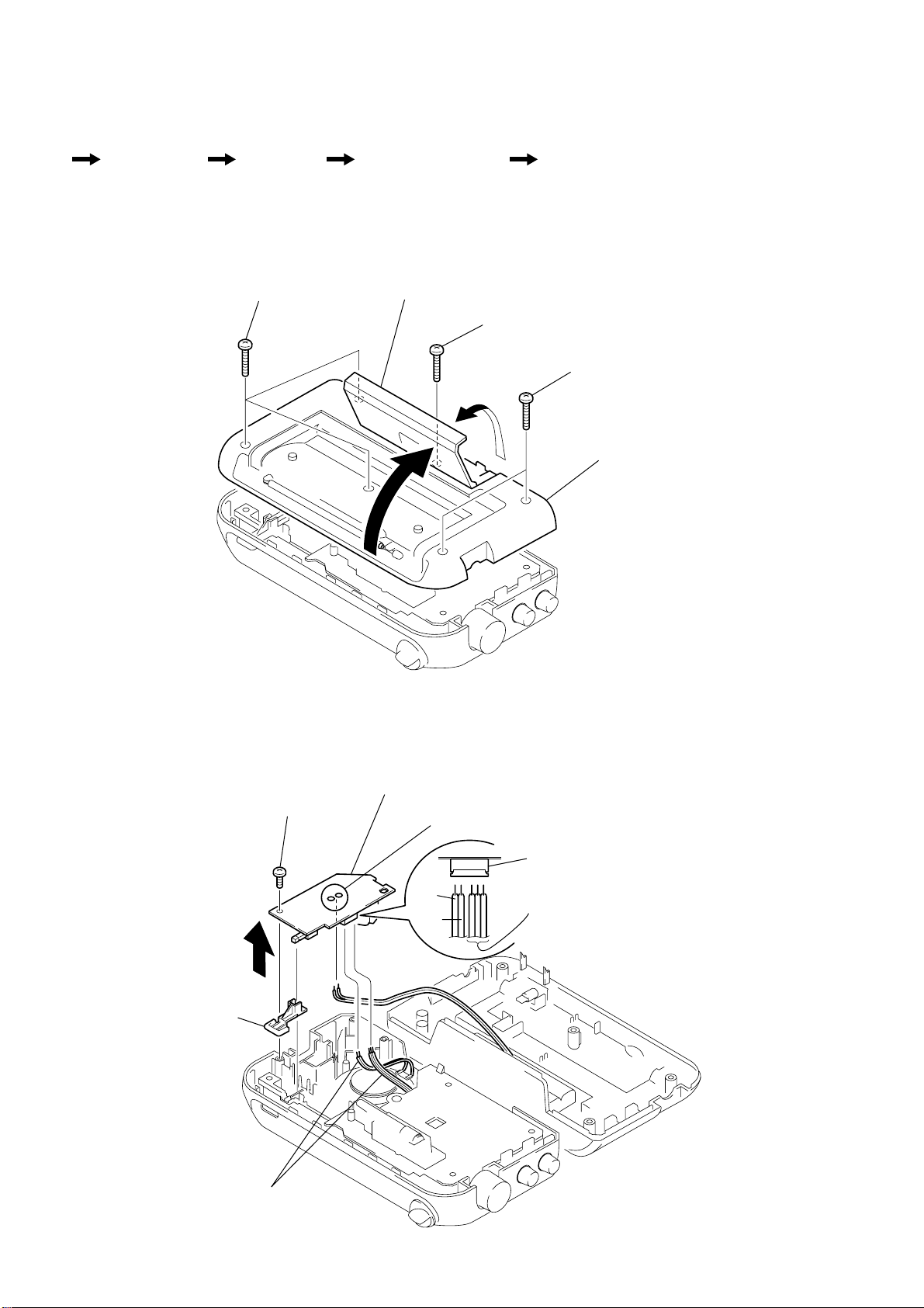
5-1. CABINET (FRONT) SECTION
51 3-045-684-01 CABINET (REAR) (BLACK)
51 3-045-684-11 CABINET (REAR) (WHITE)
51 3-045-684-21 CABINET (REAR) (DARK BLACK)
52 3-049-207-01 CUSHION (BATTERY) (B)
53 3-049-448-01 CUSHION (BATTERY) (D)
54 3-043-717-01 SPRING (HANDLE)
55 7-685-903-31 SCREW +PTPWH 3X10 (TYPE2)
56 3-049-447-01 CUSHION (BATTERY) (C)
57 3-043-335-01 SHAFT (HANDLE)
58 7-685-903-21 SCREW +PTPWH 3X8 (TYPE2)
59 3-049-592-01 SPRING (HANDLE) (B)
60 7-685-534-14 SCREW +BTP 2.6X8 TYPE2 N-S
61 7-623-508-01 LUG, 3
62 3-043-334-01 HANDLE (BLACK)
62 3-043-334-11 HANDLE (WHITE)
63 3-043-334-21 HANDLE (DARK BLACK)
63 3-043-718-01 TERMINAL (+.–), BATTERY
64 3-049-208-01 CUSHION (HANDLE)
65 3-043-331-01 LID, BATTERY CASE (BLACK)
65 3-043-331-11 LID, BATTERY CASE (WHITE)
65 3-043-331-21 LID, BATTERY CASE (DARK BLACK)
66 9-911-815-02 CUSHION
67 3-043-719-01 TERMINAL (+), BATTERY
68 3-043-720-01 TERMINAL (–), BATTERY
ANT1 1-501-222-71 ANTENNA, TELESCOPIC (FM/SW)
Ref. No. Part No. Description Remark Ref. No. Part No. Description Remark
5-2. CABINET (REAR) SECTION
ANT1
59
60
61
57
58
62
64
63
65
66
67
68
56
54
55
51
52
53
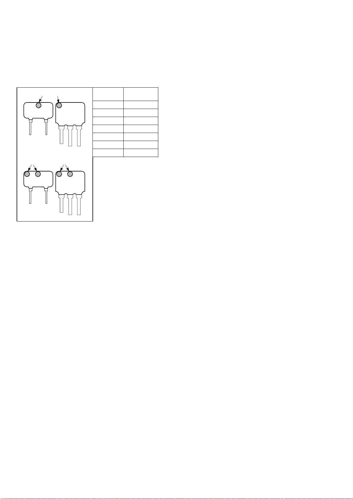
The components identified by
mark 0or dotted line with mark
0are critical for safety.
Replace only with part number
specified.
SP1 T401
2
1
3
45
67
8
17
17
17
18
18
10
9
11 12
13 14
15
16
19
20
28
27
21 30
22
23
24
25
26
29
31
Ver 1.1