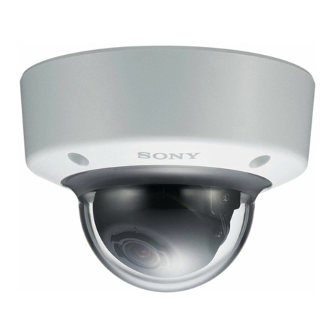
Sony SNC-WL862 User manual

Network Camera
Installation Manual
Before operating the unit, please read this manual thoroughly
and retain it for future reference.
SNC-WL862
D-963-100-12 (1)
© 2019 Sony Corporation

2
Table of Contents
About the Manuals ....................................................... 2
Location and Function of Part ....................................... 3
Preparations ................................................................. 5
Check the serial number ............................... 5
Connect cable ............................................... 5
Installing a microSD card .............................. 8
Installing the Camera .................................... 8
Adjustment of the Shooting Direction and
Range .......................................................... 8
Installing the Dome Cover ............................ 9
Important precautions .................................10
Connecting to the I/O combo cable ............................. 11
Connection ..................................................................13
Connecting the Power Source ..................... 13
Connecting to 24V AC source ...................... 13
Connecting to the Network ......................... 13
Assigning the IP address ............................................13
Specifications ..............................................................14
About the Manuals
Safety Regulations (supplied)
The Safety Regulations describes the secure usage
of camera. Be sure to read it.
Installation Manual (this document/Web)
This Installation Manual describes the names and
functions of parts and controls of the Network
Camera, gives connection examples and explains
how to set up the camera. Be sure to read the
Installation Manual before operating.
User’s Guide/Application Guide
• How to control the camera via a web browser
• How to setup the camera
Operate the camera referring to the guide above
after having installed and connected the camera
properly based on the Installation manual.

3
Location and Function of Part
Outer View
Microphone
Dome cover
Top mounting plate
Threaded holes for mounting accessories
Through holes for mounting accessories
Unlock button
Inner View
The figure shows the camera without the dome
cover.
Lens (sensor) module
3-axis adjustable
Slide track
microSD card slot
This slot is used for separately sold microSD
memory cards. Image data in the camera can be
recorded to a memory card by inserting it into the
slot.
Gently insert the memory card to the slot until it
clicks into place.
This unit is compatible with the memory cards of
microSDXC and microSDHC standards only.
Safety tether wire for the dome cover
Reset button
The reset button is used to reset the system or
restore the factory default settings.
Reset: Press the recessed reset button. Wait for the
Network Camera to reboot.
Restore: Press and hold the reset button until the
Power indicator rapidly blinks.
Note that all settings will be restored to factory
default. Once successfully restored, the Power
indicator will light up.
POWER indicator
When power is supplied to the camera, the
indicator will light up.

4
NETWORK indicator
The indicator lights up or flashes when the camera
is connected to the network. The indicator is off
when the camera is not connected to the network.
Cable gland for Ethernet
Cable gland for I/O combo cable
Note
Take care not to trap the cables between the
camera and the ceiling or the wall. If the cable is
trapped, it may cause a fire or electric shock due to
breaking.
J14 header
J9 header
Microphone contacts
RJ45 Ethernet port
Connect a commercially available network cable
(CAT5e or CAT6) to communicate with a network or
PoE* system.
For details on connection, see the Instruction
Manual of the power supply equipment.
(*PoE stands for Power over Ethernet. PoE is
compliant with IEEE802.3at.)
I/O combo cable
GPIO
+5V: I/O power supply 5V DC
DO: Digital Output (alarm output)
DI: Digital Input (sensor input)
GND: Ground
For details on each function and required
settings, see the User’s Guide.
For the wiring,see “Connecting to the I/O combo
cable”.
24V AC
24V AC power input
Ext. MIC IN (external microphone input) (Red)
External microphone input connector (Mini jack,
monaural)
Connect a commercially available microphone. This
jack supports plug-in-power (reference voltage
2.5V DC) microphones.
Audio Out (Green)
Connect a commercially available speaker with the
built-in amplifier.

5
Preparations
Check the serial number
Write down the serial number and MAC address on
the camera label for later reference.
Connect cable
To connect a cable in order to suit your
requirements, perform the following steps.
1
Remove the dome cover.
Open the dome cover by loosening 4 T10 anti-
tamper screws.
2
Remove the waterproof connectors.
If you do not need to route I/O wires, leave the
plastic cap in place. If you need to connect I/O
wires, keep the stainless nut.
Use an Ethernet cable with a cable diameter
between ø5 mm (13/64 inches) to ø6.3 mm
(1/4 inches).
3
Make holes in the ceiling.
Attach the Alignment Sticker to a position you
prefer.
Drill screw holes where “Drill hole” and “cable
hole” are indicated.
5 to 6.3 mm

6
4
Route cables through the holes.
Route cables through the routing holes, and
secure the top mounting plate to ceiling by
driving the included screws.
5
Pass an Ethernet cable through the routing
hole.
6
Hook up the tether wire between the camera
and the top mounting plate.
7
Pass the Ethernet cable through the
components of the waterproof cable gland.
8
Firmly crimp the RJ45 plug to the Ethernet
cable.
Note
For attaching the connector to the network cable,
you need a crimper (RJ45).
Length of the screws:
30 mm

7
9
Tighten and install the components of the
waterproof connector.
Pass the I/O combo cable (if applied) through the
routing hole, and attach a rubber seal ring. Install
the combo cable with the white headers inside the
camera, and tighten the stainless hex nut from the
inside of the camera.
Connect the white headers of the I/O combo cable
to the J9 and J14 headers on the camera PCB board.
10
Connect the I/O combo cable on the outside of
the cameras.
Note
Protect against moisture by using putties.
11
Connect a ground wire.
Prepare a cable with a resistance lower than
4Ω and a diameter larger than 20AWG.
Connect the ground wire to the camera with an
M4 screw.

8
Installing a microSD card
Gently insert the memory card into the slot until it
clicks into place as required.
Installing the Camera
Secure the camera to the top mounting plate by
using the alignment marks. Align the rotate the
camera clockwise. Ensure that the unlock button is
firmly in place.
Warning
• If you attach the camera in the height such as the
wall or the ceiling, etc., entrust the installation to
an experienced contractor or installer.
• If you install the camera at a height, ensure that
the installation location and its material are
strong enough to withstand a weight of 10 kg
(22 lb 0.74 oz) or more, and then install the
camera securely. If the ceiling is not strong
enough, the camera may fall and cause serious
injury.
• To prevent the camera from falling, make sure to
attach the supplied safety tether wire.
• If you attach the camera to the ceiling, check
periodically, at least once a year, to ensure that
the connection has not loosened. If conditions
warrant, make this periodic check more
frequently.
• Install the mounting plate and the camera unit to
a clean, flat, and level location that has no
deformities. Otherwise, installation may not be
possible.
Adjustment of the Shooting Direction and
Range
1
Open the live view on your laptop.
Check the live view to ensure the image is in
focus.
2
Adjust the lens shooting direction to obtain an
optimal field of view.
You can adjust the ranges of the pan, tilt, and
rotation for each lens. Move the lens module
left and right on the slide track, or without
changing the position of the lens module by
loosening the screw.
Unlock button

9
Notes
• Distortion other than the specified optical area of
the dome cover also may be appear on the
images depending on zooming, tilting or
rotation.
• When adjusting the shooting angle, please avoid
touching the exposed circuit board or ribbon
cable. Static discharge can cause damages.
3
Perform necessary adjustments such as the
image alignments on the panoramic view from
the 4 sensors.
Go to Configuration > Media > Image > Focus in
your web browser. Zoom in on the individual
lens if necessary. The automated focus
function can help you acquire the best image.
The zoom in/zoom out function is performed
in the Focus window.
4
Tighten the pan fixing screw and the tilt fixing
screw.
Tighten the screw with the tightening torque
below.
Pan: 24.5N •cm ± 1N •cm
Tilt: 44.1N •cm ± 2.9N •cm
Note
Tightening the tilt fixed screw with force more than
specified may cause a damage or deformation of
the screw.
Installing the Dome Cover
1
Replace the 2 desiccant bags on the sides of
the camera.
They remove the moisture in the dome.
Replace the desiccant every time you open the
dome cover.
2
Aim the center of the dome cover (the center of
the logo) and align with the alignment mark on
the camera body.
Aim and then turn clockwise. Install the dome
cover by fastening the T10 anti-tamper screws.

10
Note
Make sure the safety tether wire for the dome cover
does not get caught between the dome cover and
camera unit.
Important precautions
• Despite the fact that this unit is rated IP66, this
section includes important precautions to
prevent any malfunction caused by condensation
and/or water ingress.
• Read the precautions below thoroughly before
installing the unit.
• Make sure to install the camera unit so that the
surface of the connection cables (including
connectors) does not water. Or waterproof
should be performed properly. Otherwise, there
may be a risk that water enters the unit through
these cables.
• Install the mounting plate and the camera on an
even ceiling or wall, etc.
• Install the camera properly, using the screws,
while referring to the Installation Manual.
• Before attaching the dome casing to the camera
unit, make sure the waterproof rubber gasket is
clean and fits in the groove of the joint surface
properly.
• When installing the camera on a wall, install it
with the microphone hole facing down.

11
Connecting to the I/O combo cable
Dry contact with external DC power source to supply a relay. Dry contact is the safest connection to protect
devices.
Dry contact
Wet contact
External DC power
Switch
Photo
Coupler
External AC Power
with Protected Earth
External Device
DC
0V
NC
Relay
DC 0V
NO
External DC power
Switch
External AC Power
with Protected Earth
External Device
NO NC
Relay
DC 0V

12
1
The +5V pin provides a 5V output voltage, and the max. load is 50mA.
2
The max. voltage for DO pins is 30V DC (External power).
In order to control AC devices, the Wet contact diagram can be taken in consideration. The diagram
uses a relay to control the ON/OFF condition of the AC device.
3
An external relay can be triggered by using +5V pin or by an external power source, depending on the
type of relay you use.
Dry contact and using camera’s DO+ to supply a relay
Switch
External AC Power
with Protected Earth
External Device
NO NC
Relay

13
Connection
Connecting the Power Source
There are two ways to supply the power source to
this camera, as follows.
•AC24V
• Power supply equipment pursuant to IEEE802.3at
(PoE+ * system)
* PoE means Power over Ethernet.
Depending on the requirements of your
installation site, select an appropriate power
source.
• Do not turn off the camera immediately after
turning it on. Wait for at least five minutes before
turning off the camera.
• Do not connect the power input cable if power is
supplied by a PoE system.
• The ambient temperature must be -30ºC or
higher at startup of the camera.
• When using the camera in a very low
temperature environment, the embedded heater
may take up to 10 minutes to warm up the
camera. When the temperature within the
canister reaches -10ºC, the camera automatically
starts.
Connecting to 24V AC source
Connect the power input cable of the camera to a
24V AC source.
• Use a 24V AC source isolated from 100V AC. The
usable voltage range is as follows. (Assured
range of the voltage the camera is receiving
(receiving-end voltage).)
24V AC: 21.6V to 26.4V
• Use a UL cable (VW-1style 10368) for this
connection.
The AWG #16 to #20 is recommended.
• Use the following plug when connecting from a
24V AC source.
AC plug: straight PL03B, 5.5 mm outer diameter,
2.1 mm inner diameter
• The AWG #26 or thicker is recommended for I/O
combo cable signals.
Connecting to the Network
Connect the Ethernet port of the camera to a router
or hub in the network using a commercially
available network cable (not supplied).
Assigning the IP address
1
Download the installer of “SNC toolbox” in the
appropriate folder from the download site.
2
Install the SNC toolbox.
Unzip the ZIP file of the downloaded installer.
Double-click “SncToolbox_Setup.exe.”
For details on installing and use refer to the
Application Guide.
3
Assign an IP address to the camera.
Assign an IP address to the camera using the
installed SNC toolbox.
For details, see “Using SNC toolbox” - “Assign
an IP address” in the Application Guide.
Tip
SNC toolbox stands for Sony Network Camera
toolbox.

14
Specifications
Item Description
Camera
Image Sensor 1/2.8" Progressive CMOS sensor
Number of Image Sensor 4
Number of Effective Pixels Approx. 5.16 megapixels x4
Minimum Illumination (50 IRE) 0.15 lux (F1.9 1/30s)
Number of Horizontal Viewing
Angle
88.8° to 40.2°
Number of Vertical Viewing Angle 59.8° to 28.6°
Focal Length f = 3.7 to 7.7 mm
F-Number F1.9 to F2.9
Minimum Object Distance 500 mm
Pan/Tilt/Rotation Angle (manual) Pan - Track: 90° to 120° each lens
Tilt: 0° to 105° each lens
Rotation: -90° to +90° each lens
Video
Compression Format H.265, H.264 (Baseline Profile), JPEG
Maximum Frame Rate H.265: 30fps (2560 x 1090) x4
Audio
Compression Format G.711 (bit rate: 64 kbps, sampling frequency: 8 kHz)
G.726 (bit rate: 40, 32, 24, 16 kbps, sampling frequency: 8 kHz)
Interface
Network Port 10BASE-T/100BASE-TX (RJ-45)
Microphone Input Built-in microphone ×1, External input ×1 Mini jack (monaural 2.2kΩ,
plug-in-power)
Speaker Output Mini jack ×1 (monaural)
Digital Input (Sensor Input) ×1
Digital Output (Alarm Output) ×1
Card Slots microSD ×1
General
Power Requirements IEEE 802.3at Class4 compliant (PoE)
24V AC 50/60Hz
Power Consumption Max. 24 W
Operating Temperature -40ºC to +50ºC
Startup Temperature
Environments
-30ºC to +50ºC
Storage Temperature -20ºC to +60ºC
Operating Humidity 20% to 90% (no condensation)
Storage Humidity 20% to 80% (no condensation)

15
Dimensions (Diameter × Height)
[The values for dimensions are
approximate.]
Mass Approx. 1660 g (without the top mounting plate)
Supplied Accessories Top mounting plate (1), I/O combo cable (1), Alignment Sticker (1),
Screwdriver (1), Screw (M6 × 3), Screw (M5 × 3), Screw (M4 × 3), Wall
Plug (M5 × 3), Safety Regulations (1)
Recommendation of Periodic Inspections
In case using this device over an extended period of time, please have it inspected periodically for safe
use.
It may appear flawless, but the components may have deteriorated over time, which may cause a
malfunction or accident.
For details, please consult the store of purchase or an authorized Sony dealer.
Caution
The Network Camera is to be connected only to PoE networks without routing to the outside plant.
Item Description
110.4 mm
(4 3/8 inches)
Ø 210 mm (8 1/4 inches)
Sony Corporation
Table of contents
Other Sony Security Camera manuals

Sony
Sony DXC-H10 User manual

Sony
Sony SNC-M3 - Pan/Tilt IP Network Camera User manual

Sony
Sony IPELA SNC-DF40N User manual

Sony
Sony XCHR90 User manual

Sony
Sony SSC-CB564R User manual

Sony
Sony Ipela SNC-DH210 User manual

Sony
Sony CD15L User manual

Sony
Sony SNC-M3W User manual

Sony
Sony SSC-DC174 User manual

Sony
Sony IPELA SNC-CH140 User manual

Sony
Sony Super HAD CCD SSC-CD73V User manual

Sony
Sony SNC-DH110 User manual

Sony
Sony SNCVM601 User manual

Sony
Sony BRC-Z700 - CCTV Camera User manual

Sony
Sony SNC-RZ25N - Network Camera User manual

Sony
Sony Ipela SNCA-ZX104 User manual

Sony
Sony Ipela SNC-CS50N User manual

Sony
Sony EVI-H100S User manual

Sony
Sony XC-HR50 User manual

Sony
Sony SNC-RH164 User manual