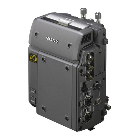
Sony SDX-D550V Manual

SDX-D550V/D450V/D250V/2-546-779-02(1)
SDX-D550V/D450V/D250V
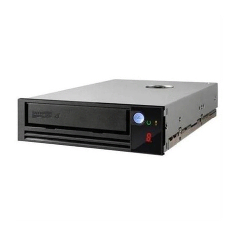
AIT Drive Unit
2-546-779-02(1)
Operator’s Guide –––––––––page 2
取扱説明書
–––––––––––––––30
ページ
Mode d’emploi –––––––––––page 61
Benutzerhandbuch –––––––Seite 89
Guía del operador ––––––––página 117
–––––––––––––––––145
–––––––––––––––––171

2Safety Regulations
Safety Regulations
Owner’s Record
The model and serial numbers are located on the bottom. Record the serial
number in the space provided below.
Refer to them whenever you call upon your dealer regarding this product.
Model No. Serial No.
________________________ __________________________________
Information
WARNING
To prevent fire or shock hazard, do not expose the
unit to rain or moisture.
To avoid electrical shock, do not open the cabinet.
Refer servicing to qualified personnel only.
Model No. for Regulatory Compliance
Your SDX-D550V is assigned a Model No.: ATDEA3 for regulatory
compliance certifications.
Your SDX-D450V and SDX-D250V are assigned a Model No.: ATDEA2 for
regulatory compliance certifications.
The number is indicated on the model number label on your drive along with
the rated voltage and current.
For the customers in the USA
You are cautioned that any changes or modifications not expressly approved
in this manual could void your authority to operate this equipment.
If you have any questions about this product, please refer to Sony contact in
the instruction manual.
DECLARATION OF CONFORMITY
Trade Name: SONY
Model: ATDEA2, ATDEA3
Responsible Party: Sony Electronics Inc.
Address: 16450 W. Bernardo Dr., San Diego,
CA 92127 U.S.A.
Telephone number: 858-942-2230
This device complies with part 15 of the FCC Rules. Operation is subject to
the following two conditions:
(1) This device may not cause harmful interference.
(2) This device must accept any interference received, including
interference that may cause undesired operation.

Safety Regulations 3
WARNING
Note: This equipment has been tested and found to comply with the limits
for a Class B digital device, pursuant to Part 15 of the FCC Rules. These
limits are designed to provide reasonable protection against harmful
interference in a residential installation. This equipment generates, uses and
can radiate radio frequency energy and, if not installed and used in
accordance with the instructions, may cause harmful interference to radio
communications. However, there is no guarantee that interference will not
occur in a particular installation. If this equipment does cause harmful
interference to radio or television reception, which can be determined by
turning the equipment off and on, the user is encouraged to try to correct the
interference by one or more of the following measures:
•Reorient or relocate the receiving antenna.
•Increase the separation between the equipment and receiver.
•Connect the equipment into an outlet on a circuit different from that to
which the receiver is connected.
•Consult the dealer or an experienced radio/TV technician for help.
This device requires shielded interface cables to comply with FCC emission
limits.
CAUTION
The mains plug on this equipment must be used to disconnect mains power.
Please ensure that the socket outlet is installed near the equipment and shall
be easily accessible.
ACHTUNG
Zur Trennung vom Netz ist der Netzstecker aus der Steckdose zu ziehen,
welche sich in der Nähe des Gerätes befinden muß und leicht zugänglich
sein soll.
Hinweis: Der höchste Schalldruckpegel beträgt 70 dB (A) oder weniger
gemäß ISO 7779
NOTICE
Use the power cord set approved by the appropriate testing organization for
the specific countries where this unit is to be used.
HINWEIS
Die 3-adrige Geräteanschlußleitung muß Typ H05VV-F oder H05VVH2-F
sein und nach DIN VDE 0625 geprüft sein. Der Stecker und die
Gerätesteckdose müssen nach DIN VDE 0620 bzw DIN VDE 0625 geprüft
sein. Der Leitungsquerschnitt kann 0,5 mm2betragen wenn die
Anschlußleitung eine Länge von 2 m nicht überschreitet. Anderenfalls muß
der Leitungsquerschnitt mindestens 0,75 mm2betragen.
English

4Safety Regulations
Für Kunden in Deutschland
Diese Ausrüstung erfüllt die Europäischen EMC-Bestimmungen für die
Verwendung in folgender/folgenden Umgebung(en):
– Wohngegenden
– Gewerbegebiete
– Leichtindustriegebiete
(Diese Ausrüstung erfüllt die Bestimmungen der Norm EN 55022, Klasse
B.)

Safety Regulations 5
IMPORTANT SAFEGUARDS
For your protection, please read these safety
instructions completely before operating the
appliance, and keep this manual for future
reference.
Carefully observe all warnings, precautions and
instructions on the appliance, or the one described
in the operating instructions and adhere to them.
USE
Power Sources – This unit should be operated
only from the type of power source indicated on
the marking label. If you are not sure of the type
of electrical power, consult your dealer or local
power company.
For the unit with a three-wire grounding type
ac plug:
If you are unable to insert the plug into the outlet,
contact your electrician to have a suitable plug
installed. Do not defeat the safety purpose of the
grounding plug.
AC Power cord:
The AC power cord should have appropriate safety
approvals or marking for the country in which the
equipment will be used. Consult your dealer or
local power company.
Cleaning – Unplug the unit from the wall outlet
before cleaning or polishing it. Do not use liquid
cleaners or aerosol cleaners.
Use a cloth lightly dampened with water for
cleaning the exterior of the unit.
Object and Liquid Entry – Never push objects of
any kind into the unit through openings as they
may touch dangerous voltage points or short out
parts that could result in a fire or electric shock.
Never spill liquid of any kind on the unit.

6Safety Regulations
INSTALLATION
Water and Moisture – Do not use power-line
operated units near water - for example, near a
bathtub, washbowl, kitchen sink, or laundry tub, in
a wet basement, or near a swimming pool, etc.
Power-Cord Protection – Route the power cord
so that it is not likely to be walked on or pinched
by items placed upon or against them, paying
particular attention to the plugs, receptacles, and
the point where the cord exits from the appliance.
Accessories – Do not place the unit on an unstable
cart, stand, tripod, bracket, or table. The unit may
fall, causing serious injury to a child or an adult,
and serious damage to the unit. Use only a cart
stand tripod, bracket, or table recommended by the
manufacturer.
Ventilation – The slots and openings in the
cabinet are provided for necessary ventilation. To
ensure reliable operation of the unit, and to protect
it from overheating, these slots and openings must
never be blocked or covered.
•Never cover the slots and openings with a cloth
or other materials.
•Never block the slots and openings by placing
the unit on a bed, sofa, rug or other similar
surface.
•Never place the unit in a confined space, such as
a bookcase, or built-in cabinet, unless proper
ventilation is provided.
SERVICE
Damage Requiring Service – Unplug the unit
from the wall outlet and refer servicing to qualified
service personnel under the following conditions:
•When the power cord or plug is damaged or
frayed.
•If liquid has been spilled or objects have fallen
into the unit.
•If the unit has been exposed to rain or water.
•If the unit has been subject to excessive shock by
being dropped, or the cabinet has been damaged.
•If the unit does not operate normally when
following the operating instructions. Adjust
only those controls that are specified in the
operating instructions. Improper adjustment of
other controls may result in damage and will
often require extensive work by a qualified
technician to restore the unit to normal
operation.
• When the unit exhibits a distinct change in
performance - this indicates a need for service.
Servicing – Do not attempt to service the unit
yourself as opening or removing covers may
expose you to dangerous voltage or other hazards.
Refer to all servicing to qualified service
personnel.

Table of Contents 7
Table of Contents
Part 1.
Introduction
How to Use this Guide ...................................................................... 8
About AIT Drives ............................................................................... 9
Features .................................................................................................... 9
Useable Cartridges ................................................................................. 10
System Components .............................................................................. 10
Part Names and Functions ............................................................. 11
Front Panel ............................................................................................. 11
Rear Panel .............................................................................................. 12
Part 2.
Preparation
Supplied Items................................................................................. 13
Interconnections ............................................................................. 13
SCSI ID Setting ................................................................................ 14
Option Switches (DIP Switch) ........................................................ 14
Part 3.
Operation
How to use the AIT Drive ................................................................ 17
Cartridge Removal ................................................................................. 18
Attaching the Dust Cover ............................................................... 19
WORM Function .............................................................................. 21
Part 4.
Care and
Maintenance
Taking Care of the Drive ................................................................. 23
Safety Considerations ............................................................................ 23
Avoiding Damage .................................................................................. 23
Taking Care of Cartridges .............................................................. 25
Use Precautions ..................................................................................... 25
Storage Precautions ............................................................................... 25
Head Cleaning ................................................................................. 26
How to Clean ......................................................................................... 26
Appendix Specifications (SDX-D550V) ........................................................... 27
Specifications (SDX-D450V) ........................................................... 28
Specifications (SDX-D250V) ........................................................... 29

8How to Use this Guide
How to Use this Guide
This Guide describes the AIT Drive Unit SDX-D550V/SDX-D450V/SDX-
D250V, and how to take care of it. Please read it carefully before using the
unit, and keep it handy for future reference.
The Guide consists of four parts, plus the specifications. Refer to the parts
that relate to your use of the drive.
Part 1 describes the features of the drive, its system components, and the
name and function of each part.
Part 2 describes the necessary connections between the drive and the host
computer. If other SCSI devices are being used, you may need to change the
SCSI ID setting. Read this part if you are installing the drive.
Part 3 describes how to use the drive, including how to turn it on, and how
to insert and remove cartridges. Read this part if you are going to operate the
drive.
Part 4 describes how to take care of the drive and cartridges, and how to
clean the drive heads. Read this part before using the drive.
Appendix provides the major specifications of the SDX-D550V/SDX-
D450V/SDX-D250V.

Part 1. Introduction 9
Part 1. Introduction
About AIT Drives
The SDX-D550V is an external AIT drive unit that uses data cartridges
conforming to the AIT-2 Turbo format. The SDX-D450V is an external AIT
drive unit that uses data cartridges conforming to the AIT-1 Turbo format.
The SDX-D250V is an external AIT drive unit that uses data cartridges
conforming to the AIT-E Turbo format.
The SDX-D550V supports the AIT-E Turbo, AIT-1, AIT-1 Turbo, AIT-2 and
AIT-2 Turbo formats. The SDX-D450V supports the AIT-E Turbo, AIT-1
and AIT-1 Turbo formats. The SDX-D250V only supports the AIT-E Turbo
format.
Features
The AIT Drive Unit SDX-D550V has the following features:
• Supports reading and writing to data cartridges conforming to the AIT-E
Turbo, AIT-1, AIT-1 Turbo, AIT-2 and AIT-2 Turbo formats.
•Read After Write Function and third-level error correction code guarantee
high data reliability.
•Data compression provides 208 gigabytes of storage on 186 m tape-length
AIT-2 Turbo data cartridge.*1
The native capacity is 80 gigabytes of storage on 186 m tape-length AIT-2
Turbo data cartridge.
• Stored data is automatically checked for compression.
•Ultra 160 Wide SCSI LVD/SE interface is fully supported for host
computer access.
The AIT Drive Unit SDX-D450V has the following features:
• Supports reading and writing to data cartridges conforming to the AIT-E
Turbo, AIT-1 and AIT-1 Turbo formats.
•Read After Write Function and third-level error correction code guarantee
high data reliability.
•Data compression provides 104 gigabytes of storage on 186 m tape-length
AIT-1 Turbo data cartridge.*1
The native capacity is 40 gigabytes of storage on 186 m tape-length AIT-1
Turbo data cartridge.
• Stored data is automatically checked for compression.
•Wide Ultra SCSI LVD/SE interface is fully supported for host computer
access.
*1 This is assuming 2.6:1 compression ratio.
The degree of data compression attained while recording data varies according to system
environment and data type.

10 Part 1. Introduction
The AIT Drive Unit SDX-D250V has the following features:
• Supports reading and writing to data cartridges conforming to the AIT-E
Turbo format.
•Read After Write Function and third-level error correction code guarantee
high data reliability.
•Data compression provides 52 gigabytes of storage on 98 m tape-length
AIT-E Turbo data cartridge.*1
The native capacity is 20 gigabytes of storage on 98 m tape-length AIT-E
Turbo data cartridge.
• Stored data is automatically checked for compression.
•Wide Ultra SCSI LVD/SE interface is fully supported for host computer
access.
*1 This is assuming 2.6:1 compression ratio.
The degree of data compression attained while recording data varies according to system
environment and data type.
Useable Cartridges
Data cartridges used with the the SDX-D550V can be used with data
cartridges marked with AIT-E Turbo, AIT-1 Turbo, AIT-2 Turbo, AIT-1 or
AIT-2 logo. The SDX-D450V must be marked with AIT-E Turbo, AIT-1
Turbo or AIT-1 logo. The SDX-D250V can be used with data cartridges
marked with the AIT-E Turbo logo.
AIT-E Turbo LOGO AIT-1 Turbo LOGO AIT-2 Turbo LOGO AIT-1 LOGO AIT-2 LOGO
Caution
•Be sure to use only the cartridges designed specifically for AIT.
•Do not use anything but AIT cartridges with this system, as doing so can
damage the AIT drive. Although commercially available 8mm videotapes
resemble AIT cartridges in appearance, they have entirely different
specifications and cannot be used.
System Components
The SDX-D550V/SDX-D450V/SDX-D250V connects to the host computer
via on Ultra Wide LVD/SE SCSI interface.
SDX-D550V
SDX-D450V
SDX-D250V
Host Computer
Peripheral Devices Terminator

Part 1. Introduction 11
Part Names and Functions
Front Panel
Advanced
Intelligent
Ta p e
12
6354
1AIT Data Cartridge Receptacle
See page 17 to 18 for information on inserting and removing a AIT data
cartridge.
2POWER Indicator
Lights while the drive is on.
3Dust Cover
This cover protects the AIT data cartridge receptacle.
4LED Indication for Drive Status
The LED indicators are defined as follows.
LED
TAPE CLEANING REPLACE Sense
MOTION REQUEST TAPE
Independent Independent Tape Loaded
Independent Independent Tape Access in Progress
(write/read)
Independent Independent Tape Access in Progress (others)
Independent Independent Cleaning is requested
Independent Independent Cleaning is Not Completed
Independent Independent Media Error Occurred
H/W Error Occurred
on
Slow
1 pulse (0.9 sec on/0.3 sec off)
Fast
1 pulse (0.3 sec on/0.3 sec off)

12 Part 1. Introduction
5EJECT Button
Push to remove a data cartridge from the drive.
6POWER Switch
Press to turn the drive on or off.
Rear Panel
1
243
1Rotary Selector Switch
SCSI ID selector.
2AC IN Connector
Connect the supplied power cable here.
3SCSI Connector
Connects to the SCSI bus connector of the host computer or another
SCSI peripheral or the terminator.
4Cooling Fan

Part 2. Preparation 13
Part 2. Preparation
After you confirm that you have all of the required accessories for your
installation, connect the drive to the host computer, and select the SCSI ID
with the rotary switch on the rear panel.
Supplied Items
When you first open the box, make sure it contains the following items.
Contact your supplier if anything is missing or broken.
•AIT Drive Unit
•Power Cable
•Operator’s Guide
Interconnections
The SCSI bus allows connection of up to fifteen peripherals to the host
computer. Use a SCSI cable with a half pitch 68 pin connector.
Precautions
•Switch off the host computer and peripherals before connecting the SCSI
cable.
•Make sure the SCSI connectors are pressed tightly together.
• If this unit is the last (or only) device on the Wide SCSI bus, make sure to
connect a terminator to the appropriate unused Wide SCSI connector. Using
an incompatible terminator may damage the unit.
•With an Ultra Wide SCSI bus, the total length of the SCSI cable(s)
connecting the host computer and the last device on the SCSI bus should be
less than 12 meters (39 feet). (If a SCSI single-end host adapter is at the end
of the SCSI bus, use less than 1.5 meters of SCSI cable.)*1
*1 It should be less than 1.5 meter, if connected to single-ended SCSI host adaptor.
AC power
Terminator

14 Part 2. Preparation
SCSI ID Setting
The SCSI ID is set by the rotary switch on the rear panel. Press the + or -
buttons to move the number up or down, respectively.
As shipped from the factory, the SCSI ID is set to 0. Press the switch buttons,
if necessary, to select the SCSI ID number you require. Because the host
adapter ID is usually set to 7, select some other value for the SCSI ID setting.
Precautions
• The SCSI ID must be different from IDs of the other peripherals on the
SCSI bus.
•When shipped from the factory, SCSI parity is enabled and Term power is
ON. Be sure to connect a terminator to the SCSI bus before use.
•Before changing the SCSI ID setting, be sure to turn off the power with the
POWER switch on the front panel.
Option Switches (DIP Switch)
Remove the two slotted screws by using a slotted screwdriver. Remove the
access cover to change the DIP switch settings. (Refer to the following
figure for details changing the DIP switch settings.)
After changing the DIP switch settings, replace access cover and tighten the
two slotted screws using a slotted screwdriver.
CAUTION
Before removing the access cover to change DIP switch settings on the
drive, turn off the computer and disconnect the power cord from the unit.
Once the DIP switch settings have been changed, replace the access cover
using the two original slotted screws provided.
Access Cover
DIP Switch
Slotted
Screws

Part 2. Preparation 15
DIP Switch Positions
Default
ON
OFF
12345678
DR (Disaster Recovery*) Mode
To enable DR Mode, set position1 [Drive Mode] Switch to ON.
ON
OFF
12345678
* In Disaster Recovery Mode, the drive enters the DR Standby Mode 15 seconds
after you insert a write-protected tape into the drive, and all the drive LED blink. If
you restart the drive while the LED are blinking, it starts as a CD-ROM device.
For details about the Disaster Recovery Mode, refer to the instruction manual that
came with the application software you are using.
1Drive Mode (OFF)
2Drive Mode (OFF)
3Drive Mode (OFF)
4Drive Mode (OFF)
5
Terminator Power (ON)
6Periodic Cleaning Req (ON)
7DC Control (1) (ON)
8DC Control (2) (OFF)
1Drive Mode (ON)
2Drive Mode
3Drive Mode
4Drive Mode
5
Terminator Power
6Periodic Cleaning Req
7DC Control (1)
8DC Control (2)

16 Part 2. Preparation
Cleaning Request Mode
Periodic cleaning requests can be enabled by a DIP switch.
ON
OFF
12345678
When switch 6 is ON, cleaning requests are enabled. When enabled, the “CLEANING
REQUEST” LED on the front panel lights after every 100 hours of operation.
When this LED lights, clean the drive with a head cleaning cartridge.
Note
To maintain the drive in optimum condition in environments affected by dust
and other contaminants, we recommend keeping cleaning requests enabled.
Terminator Power Control DIP switch
This DIP switch determines whether terminator power is supplied to the
SCSI bus. To enable terminator power, set position 5 [Terminator Power]
switch to ON.
Data Compression Control DIP Switch
Data compression can be selected by DIP switches. Data compression is
enabled while position 7 [DC Control (1)] is ON. Control by host can be
disabled when position 8 [DC Control (2)] is ON.
1Drive Mode
2Drive Mode
3Drive Mode
4Drive Mode
5
Terminator Power
6Periodic Cleaning Req (ON)
7DC Control (1)
8DC Control (2)

Part 3. Operation 17
Part 3. Operation
This section describes how to use the AIT drive, and how to handle data
cartridges.
How to use the AIT Drive
1Press the POWER switch on the front panel.
The POWER indicator should light, and the TAPE MOTION,
CLEANING REQUEST, and REPLACE TAPE indicators should blink
as the self-test is performed.
2When the three indicators stop blinking, open the dust cover and insert a
data cartridge as shown below. The TAPE MOTION indicator lights.
3Computer software controls the reading and writing of tapes. While
reading or writing, the TAPE MOTION indicator blinks.
4Close the dust cover.

18 Part 3. Operation
Cartridge Removal
1Press the EJECT button.
2Open the dust cover.
The cartridge is ejected automatically.
Caution
Do not push the EJECT button while the TAPE MOTION indicator is
blinking. To do so may destroy data on the tape.
3Remove the cartridge from the receptacle, and then close the dust cover.

Part 3. Operation 19
Attaching the Dust Cover
If the dust cover comes loose, attach it as described below.
Note
We recommend that you use the drive with the dust cover.
1Align the dust cover’s hinge clips (one on each side) with the pins of the
drive bezel.
• The dust cover should be positioned so that the magnets*on the cover’s
back face the drive bezel.
*This magnet does not affect the tape of the cartridge.
•Holding the dust cover at an angle as shown in the figure below, set the
hinge clips on top of the bezel pins, positioning them so that they
bracket the pins.
Bezel pin
Magnet
Hinge clip

20 Part 3. Operation
2Press down at an angle on each side in turn until you hear the hinge clips
click into place.
Caution
Do not press the dust cover in horizontally from the front. Doing so
could cause the dust cover to break.
3Close the dust cover.
This completes attachment of the dust cover.
This manual suits for next models
2
Table of contents
Languages:
Other Sony Storage manuals

Sony
Sony Microvault USM1GL User manual

Sony
Sony SF Series User manual

Sony
Sony SDZ-S100 User manual

Sony
Sony CSM-100BS User manual

Sony
Sony QD Series User manual

Sony
Sony SDX-550V User manual

Sony
Sony PCV-LX810 - Vaio Slimtop Computer User manual

Sony
Sony PMW-RX50 User manual

Sony
Sony MS-EX1G User manual

Sony
Sony CSMA-EX200S User manual
Popular Storage manuals by other brands

Freecom
Freecom 3.5 " / USB 2.0 / ESATA manual

Solplanet
Solplanet ASW0400/1250A-S Quick installation guide

Sans Digital
Sans Digital EliteSTOR ES208X12 Quick installation guide

Quantum
Quantum Atlas II Settings guide

Beemo
Beemo BeeBox 503 user manual

SimpleTech
SimpleTech SimpleDrive SP-U25/160 Specifications