Self-diagnosis function
When an error occurs, information can be displayed on
a terminal connected to the primary station.
Additional functions
When a DVS-V3232B or DVS-V6464B SDI Router or a
BKPF-R70 Advanced Router Controller is designated as
a primary station, and a BVS-V3232 as a secondary
station, the following functions are available:
Crosspoint disable function
Limits the selection of input sources to output
destinations.
Password function
Allows a password to be entered to prevent
unauthorized users from accessing the system.
Name setting function
Individual names can be assigned to distinguish
between connected signals. Two methods are available
for setting the names, either entering the device name
and number (for example VTR 1) or a description using
up to 16 alphanumeric characters. These names can be
displayed on optional BKS-R3280 / R3281 Display Units
and BKS-R1607/ R3202/ R3205/ R3206/ R3210 Router
Control Panels.
Virtual mapping function
Switching area can be set on/as a virtual matrix.
Free assignment function
A different connector number can be assigned to a
connector name on each level.
Tie line function
The tie-line management allows automatic selection of
the signal line that connects two or three routing
switchers.
Optional switcher components
BKDS-RS1690 Backup Control Board
This board is identical to the CPU-94 board fitted as
standard in the BVS-V3232. In the event of a fault in this
CPU, this backup board works automatically to ensure
continued operation.
BKDS-PV3291 Backup Power Supply Unit
The optional BKDS-PV3291 is identical to the standard
power supply unit and can be fitted to ensure that
power is maintained to the installed boards. It can be
easily installed or removed from the front of the frame.
Hot-swappable feature
Both the BKDS-RS1690 and BKDS-PV3291 are
hot-swappable to minimize the down time required for
service and maintenance.
Note: The power switch on the BKDS-PV3291 should be in the off-position during swapping.
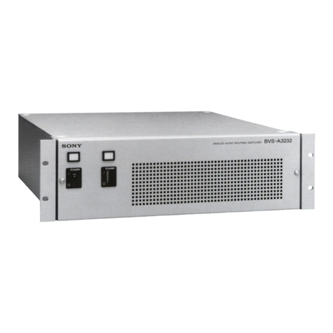
BVS-V3232
AnalogVideo Routing Switcher
Features
Simultaneous control of multiple signals
Sony routers are available to handle different types of
signals: digital and analog video, digital and analog
audio, time code and RS-422A remote control.
A practical example is the switching of video, audio,
time code and remote control signals to a VTR. Each
type of signal to be switched is known as a ‘level’ and in
the Sony router system up to eight levels can be
individually controlled.
Two types of control systems are available for
simultaneous use with BVS-V3232 and other BVS and
DVS Series routers—the Sony S-BUS system and, for
simpler command requirements, RS-422A.
S-BUS System
The S-BUS control system transmits control signals to
routing switchers and control units via a single coaxial
cable. In an S-BUS control system, one switcher is
designated as the primary station and controls the entire
system, with the remaining switchers and control units
designated as secondary stations. The primary station
controls signal transmission between secondary
stations.
The S-BUS control system has the following features:
• LAN (Local Area Network) type control signal
transmitted over a single 75 ohm coaxial cable
• Control cable length can be up to 500 meters when
BELDEN 8281 or an equivalent cable is used.
• Connection and disconnection of switchers and control
units to an S-BUS line during normal operations
without turning the power off
• Control of multiple S-BUS lines and up to 253
switchers and control units (excluding the primary
station) from the routing switcher designated as the
primary station
• Connection of up to 128 routing switchers and control
units to one S-BUS line
• Display of errors detected by the self-diagnosis
function on the terminal connected to the primary
station of the S-BUS line
• System settings and table data made with the terminal,
together with crosspoint data, can be stored in the
memory of the primary for up to ten years
Designated input and output line protect function
This function prohibits the switching of protected output
signals from other control panels (protect function). It
also protects designated crosspoints by hiding the input
signals from all control panels and, in turn, prohibits
switching from other control panels (secret function).
Phantom function
Allows several crosspoints to be switched at the same
time.


