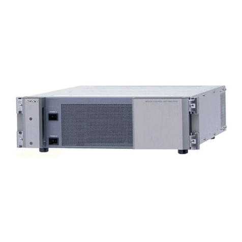
Sony BKPF-R70 User manual

ROUTING SWITCHER CONTROLLER BOARD
BKPF-R70
OPERATION MANUAL [Japanese/English]
1st Edition
Serial No. 10001 and Higher
電気製品は、安全のための注意事項を守らないと、火災
や人身事故になることがあります。
このオペレーションマニュアルには、事故を防ぐための重要な注意事項と製
品の取り扱いかたを示してあります。このオペレーションマニュアルをよく
お読みのうえ、製品を安全にお使いください。お読みになったあとは、いつ
でも見られるところに必ず保管してください。
本機をあやまって装着すると、火災・感電やその他の事故により、けがをし
たり周辺の物品に損害を与えたりすることがあります。危険を避けるため、
装着はサービストレーニングを受けた技術者にご依頼ください。
本機を装着する技術者へ
装着のしかたは、デジタルビデオインターフェースユニットに付属のマニュ
アルをご覧ください。
警告

安全のために
ソニー製品は安全に十分に配慮して設計されています。しかし電気製品は、
安全のための注意事項を守らないと、火災や感電などにより死亡や大けがな
ど人身事故につながることがあり、危険です。
事故を防ぐために次のことを必ずお守りください。
安全のための注意事項を守る
2(J)〜3(J)ページの注意事項をよくお読みください。
この「安全のために」は、ビデオインターフェースユニットまたはその関連
機器に関する安全上の注意事項を記載しています。
オプションユニットの装着について
危険を避けるために、オプションユニットの装着はサービストレーニングを
受けた技術者、もしくはソニーのサービス担当者または営業担当者にご依頼
ください。
定期点検を実施する
長期間安全に使用していただくために、定期点検を実施することをおすすめ
します。点検の内容や費用については、ソニーのサービス担当者または営業
担当者にご相談ください。
故障したら使用を中止する
ソニーのサービス担当者、または営業担当者にご連絡ください。
万一、異常が起きたら
警告表示の意味
このオペレーションマニュアル
および製品では、次のような表
示をしています。表示の内容を
よく理解してから本文をお読み
ください。
警告
この表示の注意事項を守らない
と、火災や感電などにより死亡
や大けがなど人身事故につなが
ることがあります。
注意
この表示の注意事項を守らない
と、感電やその他の事故により
けがをしたり周辺の物品に損害
を与えたりすることがあります。
注意を促す記号
行為を禁止する記号
行為を指示する記号
火災 感電
禁止
分解禁止
強制
アース線を
接続せよ
異常な音、に
おい、煙が出
たら
/
炎が出たら /
1電源を切る。
2電源コードや接続コードを抜く。
3ソニーのサービス担当者、または営業担当者に
修理を依頼する。
すぐに電源を切り、消火する。

1 (J)
目次
警告 ........................................................................................................................... 2 (J)
注意 ........................................................................................................................... 3 (J)
概要................................................................................................................................. 4 (J)
特長....................................................................................................................................4(J)
システム構成例 ................................................................................................................5(J)
各部の名称と働き...........................................................................................................6 (J)
仕様................................................................................................................................. 7 (J)
日
本
語

2 (J)
下記の注意を守らないと、
火災や感電により死亡や大けがにつながることがあります。
感電火災
警告
分解禁止
禁止
強制
禁止
禁止
強制
外装を外さない、改造しない
外装を外したり、改造したりすると、感電の原因となります。
内部の調整や設定および点検を行う必要がある場合は、必ずサービストレー
ニングを受けた技術者にご依頼ください。
内部に水や異物を入れない
水や異物が入ると火災や感電の原因となります。
万一、水や異物が入ったときは、すぐに電源を切り、電源コードや接続コー
ドを抜いて、ソニーのサービス担当者または営業担当者にご相談ください。
指定の電源コードを使用する
指定以外の電源コードを使用すると、火災や感電の原因となります。
他の電源コードを使用する場合は、ソニーのサービス担当者または営業担当
者にご相談ください。
電源コードを傷つけない
電源コードを傷つけると、火災や感電の原因となります。
・電源コードを加工したり、傷つけたりしない。
・重いものをのせたり、引っ張ったりしない。
・熱器具に近づけたり、加熱したりしない。
・電源コードを抜くときは、必ずプラグを持って抜く。
・ラックマウントするとき、レールにはさみ込まない。
万一、電源コードが傷んだら、ソニーのサービス担当者に交換をご依頼くだ
さい。
油煙、湯気、湿気、ほこりの多い場所では設置 •使用しない
上記のような場所で設置・使用すると、火災や感電の原因となります。
表示された電源電圧で使用する
機器に表示されたものと異なる電源電圧で使用すると、火災や感電の原因と
なります。

3 (J)
下記の注意を守らないと、
けがをしたり周辺の物品に損害を与えることがあります。
注意
通風孔をふさがない
通風孔をふさぐと内部に熱がこもり、火災や故障の原因となることがありま
す。風通しをよくするために次の項目をお守りください。
•壁から 10cm 以上離して設置する。
•密閉された狭い場所に押し込めない。
•毛足の長い敷物(じゅうたん・布団など)の上に設置しない。
•布などで包まない。
•あお向けや横倒し、逆さまにしない。
安定した場所に設置する
ぐらついた台の上や傾いたところなどに設置すると、製品が落下してけがの
原因となることがあります。
安全アースを接続する
安全アースを接続しないと、感電の原因となることがあります。次の方法で
アースを接続してください。
•電源コンセントが 3 極の場合
付属または別売りの電源コードセット(1-575-181-11)を使用することで安
全アースが接続されます。
•電源コンセントが 2 極の場合
付属または別売りの3極→2極変換プラグ(1-750-686-11)を使用し、変換
プラグから出ている緑色のアース線を建物に備えられているアース端子に
接続してください。
安全アースを取り付けることができない場合は、ソニーのサービス担当者ま
たは営業担当者にご相談ください。
強制
アース線を
接続せよ
禁止
変換プラグ
アース線

4 (J)
概要
ルーティングスイッチャーコントローラーボードBKPF-R70は、S-BUS
リモートの1次局用基板です。ビデオルーティングスイッチャー
DVS-V6464Bを1次局としたときと同じ機能を持ち、通信処理の高
速化を可能にします。デジタルビデオスイッチャーDVS-7000と組
み合わせたシステムでは、タリーレスポンスが改善されます。
8入力セレクターボードBKPF-300シリーズを多数使用するときの1
次局として利用すると、同一筐体に挿入することができます。
本基板は、デジタルビデオインターフェースユニットPFV-D10、
PFV-D20、PFV-D50、PFV-D100A、PFV-D200A、PFV-D300に組
み込んで使用します。動作に必要な電源は、インターフェースユ
ニットから供 給されます。
BKPF-R70の構造および電源電圧は、デジタルビデオインター
フェースユニットPFV-D10/D20/D50/D100A/D200A/D300用に
企画された他の基板とすべて共通です。これらの基板は、各イン
ターフェースユニットに任意の組み合わせで装着して同時運用する
ことができ、柔軟なシステム構成が可能になります。
基板上のスイッチの設定については、サービストレーニングを受け
た技術者にご依頼ください。
BKPF-R70は以下のものから構成されます。
•基板(1)
•コネクターパネル(1)
•オペレーションマニュアル(1)
•インストレーションマニュアル(1)
•ルーティングスイッチャーデータバックアップソフトウェアBZR-10
(1)
•スロット番号ラベル
特長
ライブシステムの信号切り替えと、モニタータリー表示の
快適レスポンス
RISC(ReducedInstructionSetComputer)タイプのCPUを使い
処理の高速化を、またS-BUSリモート用CPUを2系統使い通信時
間の改善を行い、デジタルビデオルーティングスイッチャーDVS-
V6464Bをコントローラーとしたときと比較すると、最高4倍のレスポ
ンスを得ることができます。
コントロールの2重化が可能
同じ基板を2枚使用して、コントロールの2重化を行うことが できま
す。
ISR対応
専用のISRソフトを搭載しているため、BKPF-500なしでISRに対
応します。
ソフトウェアだけで構成された64×64のマトリックス機能
基板上のスイッチ選択により、ソフトウェアで構成されたマトリックス
機能を利用することができます。
設定データをフロッピーディスクに保存可能
付属のBZR-10を使ってシステム設定データをコンピューターに取
り込 み、フロッピーディスクに保存することができます。
注意

5 (J)
75Ω終端
75Ω終端
RS-232C
パーソナルコンピューター
Digital Video Interface Unit PFV-D300
75Ω終端
RS-422
REMOTE 1 A
B
C
MAIN-BACKUP
REMOTE 1 A
B
C
MAIN- BACKUP
REMOTE 3
S-BUS
S-BUS
システム構成例
BZR-10
(付属)
:T型ブリッジ
モニター
BACKUP
MAIN
Digital Video
Routing Switcher
DVS-V6464B
Digital Video
Switcher
DVS-7000
Routing Switcher
Controller Board
BKPF-R70
Routing Switcher
Controller Board
BKPF-R70
Tally Interface Unit
BKDS-7700
Digital Video Selector
Board BKPF-300
Status Display Unit Status Display Uniit Status Display Unit
BKS-R3281 BKS-R3281 BKS-R3281
Control Unit Control Unit Control Unit
BKS-R3209 BKS-R3209 BKS-R3210

6 (J)
各部の名称と働き
REMOTE 1REMOTE2REMOTE 3MAIN-BACKUP
RS-232C A CBA
BKPF-R70
CONTROLLER
1MAIN-BACKUP 端子
2REMOTE3 端子
3REMOTE2 端子
4REMOTE1 A、B、C端子
1MAIN-BACKUP(メインバックアップ)端子
(D-sub 25ピン、メス)
本基板を2枚使い、コントロールの 2 重化を行うときに 使 用します。
市販の全25ピン接続ストレートケーブルを使ってバックアップ基板
と接続してください。
ご注意
コネクターには電源接続用のピンがあり、指定外のケーブルを使っ
て接続すると、内部のヒューズが断線することがあります。断線し
た場合は、規定の容量のヒューズと交換してください。
2REMOTE(リモート)3端子 (D-sub 9ピン、オス)
パーソナルコンピューターのRS-232Cインターフェースと接続し、設
定用ターミナル機能、データバックアップ機能、ISR機能の3つの機
能の中の1つの用途に使用します。
IBM-PC/AT互換機コンピューターとの接続は、市販のRS-232Cク
ロスケーブルを使ってください。
使用する機能は、基板上のS2(TERM/ISR)スイッチで選択しま
す。
TERM
:設定用ターミナル機能、またはBZR-10を使用したデータ
バックアップ機能となります。
電源を投入した状態がどちらかの待ち状態で、[Ctrl+X]キー
を受け取ると設定用ターミナル機能となり、再度[Ctrl+X]キー
を押し設定を終了させると、電源投入と同じどちらかの機能入
力待ちとなります。
データバックアップ機能は、BZR-10を起動することにより自動
的に実行されます。
ISR
:ISR機能となります。
ISRは、S-BUSリモートケーブルの断線およびバックアップ
CPUのダウンを報告します。
3REMOTE(リモート)2端子 (D-sub 9ピン、メス)
RS-422によりコントロールするときに接続します。
入力された制御コマンドは、BKPF-R70内部で REMOTE1 (S-
BUS)に変換されます。
4REMOTE(リモート)1 A、B、C端子 (BNC型)
S-BUS通信回線で、ほかの機器と接続します。
本基板を2枚使いコントロールの 2 重化を行うときは、市販のT型
ブリッジと同軸ケーブルを使って2枚の基板のA、B、C同じ表記の
端子同志を接続してください。リモートケーブルの終端には、ルー
ティングスイッチャーに付属の75Ω終端器を使ってください。

7 (J)
仕様
電源 DC5V(PFV-D10/D20/D50/D100A/
D200A/D300より供給)
消費電流 700mA
動作温度 5〜40°C
性能保証温度 5〜40°C
保存温度 −20°C〜60°C
使用湿度 10%〜90%
外形寸法 CPU-256基板:192×317mm
(奥行き/高さ)
CN-1515コネクターパネル:217×90mm
(奥行き/高さ)
質量 CPU-256基板:520g
CN-1515コネクターパネル:160g
付属品 オペレーションマニュアル(1)
インストレーションマニュアル(1)
スロット番号ラベル (1)
ルーティングスイッチャーデータバックアッ
プソフトウェアBZR-10 (1)
仕様および外観は、改良のため予告なく変更することがあります
が、ご了承ください。

1 (E)
For the customers in the USA
This equipment has been tested and found to comply with
the limits for a Class A digital device, pursuant to Part 15 of
the FCC Rules. These limits are designed to provide
reasonable protection against harmful interference when the
equipment is operated in a commercial environment. This
equipment generates, uses, and can radiate radio frequency
energy and, if not installed and used in accordance with the
instruction manual, may cause harmful interference to radio
communications. Operation of this equipment in a residential
area is likely to cause harmful interference in which case the
user will be required to correct the interference at his own
expense.
You are cautioned that any changes or modifications not
expressly approved in this manual could void your authority
to operate this equipment.
The shielded interface cable recommended in this manual
must be used with this equipment in order to comply with the
limits for a digital device pursuant to Subpart B of Part 15 of
FCC Rules.
Für Kunden in Deutschland
Dieses Produkt kann im kommerziellen und begrenztem
Maße auch im industriellen Bereich eingesetzt werden.
Dies ist eine Einrichtung, welche die Funk-Entstörung nach
Klasse B besitzt.
English
Precaution
If this unit is installed incorrectly, personal injury or damage
to peripheral items may occur due to fire, shock, or other
accidental circumstances. To avoid such risks, installation
should be performed by qualified service technicians.
To technician installing unit
For installation instructions, please refer to the manual
supplied with the digital video interface unit.
2 (E)
Overview............................................................................................. 3 (E)
Features........................................................................................... 3 (E)
System Configuration..................................................................... 4 (E)
Location and Function of Parts ........................................................ 5 (E)
Specifications...................................................................................... 6 (E)
Table of Contents

3 (E)
Overview
The BKPF-P70 routing switcher controller board
functions as the primary station of the S-BUS remote,
and has the same functions the DVS-V6464B Digital
Video Routing Switcher has when used as the primary
station. This board enables high-speed data
transmission. When the board is used with the DVS-
7000 Sony Digital Video Switcher, the tally response
is improved.
When the board is used as the primary station in a
system using many BKPF-300 series boards, it can be
installed in the same interface unit in which the BKPF-
300-series boards are installed.
The BKPF-P70 is designed to be installed and
operated in the PFV-D10, PFV-D20, PFV-D50, PFV-
D100A, PFV-D200A or PFV-D300 digital video
interface unit. The necessary operating power is
supplied via the interface unit.
This is compatible in structure and power voltage with
other optional boards designed for the PFV-D10/D20/
D50/D100A/D200A/D300 digital video interface unit.
The boards can be mounted in these interface units in
any combination.
Note
For settings of the switches on the boards, consult a
qualified service technician.
The BKPF-R70 is composed of the following items.
Board (1)
Connector panel (1)
Operation manual (1)
Installation manual (1)
Routing switcher data backup software BZR-10 (1)
Slot number label (1)
Features
Quick response for signal switching in a live
system and monitor-tally display
The use of an RISC (Reduced Instruction Set
Computer) type CPU enables quick processing and the
use of two CPUs for the S-BUS remote improves
transmission rate, which allows 400% quicker
response than when processing on the DVS-V6464B
Digital Video Routing Switcher.
Dual control
Using two BKPF-R70 boards allows dual control.
ISR function
The software for the ISR function is included on the
board so that the ISR function is available without
using the BKPF-500.
64 x 64 matrix function configured with
software
Matrix function configured with software is available
by setting the switch on the board.
Data storage on a floppy disk
Using the supplied BZR-10, the system setting data
can be loaded into a computer and be stored on a
floppy disk.

4 (E)
System Configuration
Video monitors
BKS-R3281
Status Display Unit
BKS-R3209 Control Unit
75-ohm termination
S-BUS
RS-232C
: T bridge
Personal computer
BZR-10
(supplied)
RS-422
S-BUS
BKS-R3281
Status Display Unit BKS-R3281
Status Display Unit
BKS-R3209 Control Unit BKS-R3210 Control Unit
BKDS-7700
Tally Interface Unit
BKPF-300
Digital Video selector
Board
DVS-V6464B
Digital Video Routing
Switcher
DVS-7000
Digital Video Switcher
75-ohm termination
75-ohm termination
BKPF-R70
Routing Switcher
Controller Board
BKPF-R70
Routing Switcher
Controller Board
REMOTE1 A
B
C
MAIN-BACKUP
REMOTE1 A
B
C
MAIN-BACKUP
REMOTE3
[BACKUP]
[MAIN]
Overview
Digital Video Interface Unit PFV-D300

5 (E)
Location and Function of Parts
1MAIN-BACKUP connector (D-sub 25-pin,
female)
Used for dual operation using two BKPF-R70 boards.
Connect to the MAIN-BACKUP connector on another
BKPF-R70 using a 25-pin straight cable (available on
the market).
Note
The connector has a pin for power connection. If the
connection is made using the cable not designated, the
internal fuse may be blown. When replacing the fuse,
be sure to use the one of the specified capacity.
2REMOTE3 connector (D-sub 9-pin, male)
Used to connect to the RS-232C connector of a
personal computer. This makes one of the functions of
setting terminal, data backup, or ISR available.
To connect an IBM PC/AT compatible computer, use
an RS-232C cross cable (available on the market).
The function to be used is selected with the S2
(TERM/ISR) switch on the board.
TERM: The setting terminal function or data backup
function using a supplied BZR-10 is activated.
When the power is turned on, the computer waits
for you to activate the setting terminal function by
pressing the [Ctrl] and [X] keys. Pressing the
[Ctrl] and [X] keys again retrieves the status when
the power was turned on.
However, if you have the BZR-10 installed, the
data backup function is automatically activated.
ISR: The ISR function is activated.
The ISR function reports any disconnection of the
S-BUS remote cable or unavailability of the
backup CPU.
3REMOTE2 connector (D-sub 9-pin, female)
Used for control with an RS-422 interface.
The input control signals are converted to the S-BUS
signals in the BKPF-R70.
4REMOTE1 A, B, C connectors (BNC type)
Used to connect other devices using an S-BUS line.
For a dual operation using two BKPF-R70 boards,
connect the corresponding A, B and C connectors on
the two boards using T bridges and coaxial cables
(available on the market). To terminate the remote
cable, connect a 75-ohm terminator supplied with the
routing switcher.
REMOTE 1REMOTE2REMOTE 3MAIN-BACKUP
RS-232C A CBA
BKPF-R70
CONTROLLER
1MAIN-BACKUP connector
2REMOTE3 connector
3REMOTE2 connector
4REMOTE1 A, B, C connectors

6 (E)
Specifications
Power requirements +5 V DC (supplied from the
PFV-D10/D20/D50/D100A/
D200A/D300)
Current consumption 700 mA
Operating temperature5°C to 40°C (41°F to 104°F)
Performance guarantee temperature
5°C to 40°C (41°F to 104°F)
Operating humidity 10% to 90%
Dimensions CPU-256 board: 192 × 317 mm
(h/d) (75/8× 121/2inches)
CN-1515 board: 217 × 90 mm
(h/d) (85/8× 35/8inches)
Mass CPU-256 board: approx. 520 g
(1 lb 2 oz)
CN-1515 board: approx. 160 g
(6 oz)
Accesories supplied Operation manual (1)
Installation manual (1)
Slot number label (1)
Routing switcher data backup
software BZR-10 (1)
Design and specifications are subject to change
without notice.

The material contained in this manual consists of
information that is the property of Sony Corporation and is
intended solely for use by the purchasers of the equipment
described in this manual.
Sony Corporation expressly prohibits the duplication of any
portion of this manual or the use thereof for any purpose
other than the operation or maintenance of the equipment
described in this manual without the express written
permission of Sony Corporation.
Le matériel contenu dans ce manuel consiste en
informations qui sont la propriété de Sony Corporation et
sont destinées exclusivement à l’usage des acquéreurs de
l’équipement décrit dans ce manuel.
Sony Corporation interdit formellement la copie de quelque
partie que ce soit de ce manuel ou son emploi pour tout
autre but que des opérations ou entretiens de l’équipement
à moins d’une permission écrite de Sony Corporation.
Das in dieser Anleitung enthaltene Material besteht aus
Informationen, die Eigentum der Sony Corporation sind,
und ausschließlich zum Gebrauch durch den Käufer der in
dieser Anleitung beschriebenen Ausrüstung bestimmt sind.
Die Sony Corporation untersagt ausdrücklich die
Vervielfältigung jeglicher Teile dieser Anleitung oder den
Gebrauch derselben für irgendeinen anderen Zweck als die
Bedienung oder Wartung der in dieser Anleitung
beschriebenen Ausrüstung ohne ausdrückliche schriftliche
Erlaubnis der Sony Corporation.

Printed in Japan
1997.10.13
1997
Sony Corporation
Broadcast Products Company
Published by Broadcast Products Company
BKPF-R70
(SY, 和, 英)
3-861-333-01 (1)
Other manuals for BKPF-R70
1
Table of contents
Languages:
Other Sony Switch manuals

Sony
Sony DVS-9000 User manual

Sony
Sony MVS-8000 User manual

Sony
Sony XVS-9000 User manual

Sony
Sony MVS-8000X System User manual

Sony
Sony MVS-8000G-C Quick start guide

Sony
Sony HDS-7150 User manual

Sony
Sony HDS-X5800 User manual

Sony
Sony DVS-9000 User manual

Sony
Sony DCU-8000 User manual

Sony
Sony DVS-7150 User manual

Sony
Sony BKPF-R70 User manual

Sony
Sony DFS-700 User manual

Sony
Sony DVS-7300 User manual

Sony
Sony MVS-8000 User manual

Sony
Sony XA-C30 - 2 Output Selector User manual

Sony
Sony CAV-CVS12ES - Component Video Switcher User manual

Sony
Sony PVS-R102 User manual

Sony
Sony DVS-9000 User manual

Sony
Sony DVS-7250 User manual

Sony
Sony MVS-8000X SystemMVS-7000X System User manual