manuals.online logo
Brands
  1. Home
  2. •
  3. Brands
  4. •
  5. Sony
  6. •
  7. Switch
  8. •
  9. Sony DVS-7200A User manual

Sony DVS-7200A User manual

Printed in Japan
Sony Corporation 1999. 8 08
Broadcasting & Professional Systems Company ©1999
DIGITAL VIDEO SWITCHER
DVS-7200A
DVS-7200A (SY) E
3-203-030-01
SUPPLEMENT-1
FOR INSTALLATION MANUAL
Some of the pages in the manual for this model have been revised.
Please update the manual in your possession by adding or replacing
the indicated pages with those supplied as part of this supplement.
Applicable Manual (Manual Code)
1st Edition (3-201-868-01)
Contents
Additional information for the above models.
Section 4 Installation of Options
Section 5 Confirmation in Installation
Section 6 Initial Set-up of System
ADVANCED WIPE BOARD
BKDS-7370
FRAME MEMORY EXPANSION BOARD
BKDS-7444
1
DVS-7200AEIM
Table of Contents
Manual Structure
Purpose of this manual .............................................................................................. 4
Related manuals......................................................................................................... 4
Contents ..................................................................................................................... 5
1. Installation
1-1. Operating Environment...............................................................................1-1
1-2. Power Supply ..............................................................................................1-1
1-2-1. Power Switch for Service (Control panel) .................................1-1
1-2-2. Power Specifications ..................................................................1-1
1-2-3. Power Cord.................................................................................1-1
1-3. Connectors...................................................................................................1-2
1-4. Input and Output Signals of Connectors .....................................................1-3
1-4-1. DVS-7200A................................................................................1-3
1-4-2. BKDS-7015................................................................................1-6
1-4-3. BKDS-7025/7026.......................................................................1-8
1-5. Examples of System Connection ..............................................................1-11
2. Installation of DVS-7200A
2-1. External Dimensions ...................................................................................2-1
2-2. Rack Mounting............................................................................................2-2
3. Installation of Control Panel
3-1. External Dimensions ...................................................................................3-1
3-2. Installation Space ........................................................................................3-3
3-3. Installation of MAIN PANEL.....................................................................3-4
3-4. Installation of DISPLAY PANEL (BKDS-7025/7026)..............................3-5
3-5. Replacement of Key Tops...........................................................................3-6
2DVS-7200AEIM
4. Installation of Options
4-1. Installation of Plug-in Boards .....................................................................4-2
4-2. Combination of Optional boards .................................................................4-4
4-2-1. Function of Optional Boards ......................................................4-4
4-2-2. Relation between Optional Boards and
Rear Panel Connectors ...............................................................4-4
4-3. Installation of Options for DVS-7200A ......................................................4-6
4-3-1. Removing and Installing of Front Panel ....................................4-6
4-3-2. Inserting/Pulling Out of Plug-in Boards ....................................4-7
4-3-3. Installation of Optional Boards ..................................................4-9
4-3-4. Installation of BKDS-7690 (Redundant Power Supply Unit) ..4-12
4-3-5. Installation of BKDS-7444
(Frame Memory Expansion Board) ..................................... 4-12-1
4-4. Installation of Options for Control Panel ..................................................4-13
4-4-1. Opening and Closing of Panel..................................................4-13
4-4-2. Turning On/Off the Power Switch ...........................................4-15
4-4-3. Installation of BKDS-7001 (Control Port Expansion Board) ..4-16
4-4-4. Installation of BKDS-7002 (Source Name Display Unit)
(BKDS-7015) ...........................................................................4-17
4-4-5. Installation of BKDS-7031 Track Ball ....................................4-19
4-4-6. Installation of Option Panels
(BKDS-7030/7031/7033/7340) ................................................4-21
4-4-7. Joining of BKDS-7075 (Control Panel Remote Adaptor) .......4-29
4-4-8. Installation of BKDS-7091 (Redundant Power Supply Unit)
(BKDS-7015) ...........................................................................4-33
4-4-9. Installation of BKDS-7090 (Redundant Power Supply Unit)
(BKDS-7025/7026) ..................................................................4-34
5. Confirmation in Installation
5-1. Switch Settings on Boards and LEDs Description......................................5-1
5-1-1. DVS-7200A................................................................................5-1
5-1-2. BKDS-7133 ................................................................................5-6
5-1-3. BKDS-7015 ................................................................................5-6
5-1-4. BKDS-7091 ................................................................................5-9
5-1-5. BKDS-7025/7026.....................................................................5-10
5-1-6. BKDS-7090 ..............................................................................5-16
5-2. Adjustment of Secondary Power Supply Voltage.....................................5-17
5-2-1. DVS-7200A..............................................................................5-17
5-2-2. BKDS-7015 ..............................................................................5-19
5-2-3. BKDS-7025/7026.....................................................................5-21
5-3. Adjustment of Operation Power for Fader Lever .....................................5-23
3
DVS-7200AEIM
6. Initial Set-up of System
6-1. Operation and Saving of Set-up Data..........................................................6-1
6-2. Installation of Program (BZS-7040A/7060A) ............................................6-5
6-2-1. Down Load of Program..............................................................6-6
6-2-2. Initializing of Data on RAM ......................................................6-7
6-2-3. Initializing of “Nonvolatile Memory”........................................6-8
6-3. Set-up ..........................................................................................................6-9
6-3-1. Confirmation of the Software Version .....................................6-10
6-3-2. Setting of the Signal Format ....................................................6-10
6-3-3. Setting about the System ..........................................................6-11
6-3-4. Saving Set-up Data to Nonvolatile Memory ............................6-12
6-4. Installation of Software for Option Board ................................................6-13
4DVS-7200AEIM
Manual Structure
Purpose of this manual This manual is the installation manual of Digital Video Switcher DVS-7200A.
This manual is intended for use by trained system and service engineers, and
describes the information when installing DVS-7200A.
Related manuals The following manuals are prepared for DVS-7200A.
The part numbers of these manuals as of February, 1999 describe.
..
..
.User’s Guide (Supplied with BZS-7040A or BZS-7060A)
This manual describes the application and operation of DVS-7200A
..
..
.Operation Manual (Supplied with DVS-7200A)
This manual describes the overview, system configuration examples and specifica-
tions of options.
..
..
.Maintenance Manual Part 1 (Supplied with DVS-7200A)
This manual describes the information for the periodic maintenance, and the
information for the service with predicated on the replacement of the principal
blocks and mounted circuit boards.
Part number : 3-201-866-01
..
..
.Maintenance Manual Part 2
The following manuals describe the detailed service information. For obtaining,
please contact your local Sony’s sale/service office.
Volume 1 (Block diagrams and Frame wirings)
Part number : 9-967-615-03
Supplement 4 Part number : 9-967-615-84
Volume 2
(Spare parts, Service overview and Replacement of main parts)
Part number : 9-967-616-03
Supplement 5 Part number : 9-967-616-85
Volume 3 (Semiconductor pin assignments)
Part number : 9-967-617-03
Supplement 3 Part number : 9-967-617-83
Volume 4 (Board layouts)
Part number : 9-967-618-03
Supplement 4 Part number : 9-967-618-84
4-1
DVS-7200AEIM
Section 4
Installation of Options
Optional Equipments for DVS-7200A
Option Function name
BKDS-7103 (DI-36 board) 12Input Serial Digital Board
BKDS-7110 (ADC-21 board) Blank Input Adaptor Board
BKDS-7111 (ADI-3 board) Analog Composite Input Board
BKDS-7113 (DI-34 board) Serial Digital Input Board
BKDS-7133 (ADC-22 and ENC-34 boards) CRK Analog Component Input Board
BKDS-7161 (DA-94 board) Analog Composite Output Board
BKDS-7163 (SD-48 board) Serial Digital Output Board
BKDS-7250 (MIX-35 board) P/P DSK Board
BKDS-7270 (BD-26 board) Key Border Board
BKDS-7271 (BD-35 board) Fine Key/Key Border Board
BKDS-7280 (UP-10 board) ME PVW Board
BKDS-7340 (MIX-35 board) DSK Board/Control Panel Unit
BKDS-7370 (WKG-27 board) Advanced Wipe Board
BKDS-7420 (CC-81 board) Color Correction Board
BKDS-7444 (MY-95 board) Frame Memory Expansion Board
BKDS-7445 (YC-59 board) Frame Memory Adaptor Board
BKDS-7690 (LE-55, RE-109 and RE-110 boards) Redundant Power Supply Unit
BKDS-2031 (CRK-10 board) Chromakey Board
BKDS-2032 (CRK-11 board) Chromakey Upgrade Board
BKDS-2041 (MY-66 board) Frame Memory Board
BKDS-2070 (WKG-12 board) Enhanced Wipe Generator Board
BZS-7040A(*1) Operation Software with Manual (E)
BZS-7060A(*2) Operation Software with Manual (E)
Optional Equipments for the control panels
Option Function name
BKDS-7001 (IF-523 board) Control Port Expansion Board
BKDS-7002 (LE-147, 148, 180 and DC-92 boards) Source Name Display Unit(*3)
BKDS-7030 (KY-328 and LE-144 boards) Key Frame Control Panel Unit
BKDS-7031 (KY-329 board) DME Control Panel Unit
BKDS-7033 (KY-395C board) Memory Recall Control Panel Unit
BKDS-7075 (IF-629 board) Control Panel Remote Adaptor
BKDS-7090 (RE-112 board) Redundant Power Supply Unit
BKDS-7091 (RE-146 board) Redundant Power Supply Unit
BKDS-7340 (KY-393 and LE-142 boards) DSK Board/Control Panel Unit(*3)
(*1) : For installation of BZS-7040A, refer to the section 6 and BZS-7040A User’s Guide.
(*2) : For installation of BZS-7060A, refer to the section 6 and BZS-7060A User’s Guide.
(*3) : Those boards can be installed only on the BKDS-7015.
4-2 DVS-7200AEIM
4-1. Installation of Plug-in Boards
It is possible to be used DVS-7200A for various systems, and its functions can be extended by selecting
the optional boards. Each plug-in board must be installed in the corresponding slot of DVS-7200A.
Confirm that all the boards are in the specified slots by referring to the following table.
For the details of how to install the plug-in board, refer to “4-3-2. Inserting/Pulling Out of Plug-in
Boards”.
The board name are displayed near the eject lever at the left side on the A side of each plug-in board. The
slot numbers that can be installed the board are displayed on the inside of the front panel of DVS-7200A.
Like the standard board, each optional boards should also be installed in the specified slot according to
the slot number display.
n
(1) Confirm that the connectors on each board are securely connected to the MB-618 board of the main
unit.
(2) If the board is installed in an incorrect slot, a system error occurs. Then the system is not properly
activated.
(3) Be sure to confirm the power supply voltage when an optional board is added or a board is replaced.
(Refer to “5-2. Adjustment of Secondary Power Supply Voltage”.)
4-1. Installation of Plug-in Boards
1
CPU-264
2
YC-59
MY-66
CC-81
3 4
ENC-34
ADC-22
5
ENC-34
ADC-22
6
CRK-10
CRK-11
7
MIX-35
BD-26
BD-35
8

9
MIX-35
BD-26
BD-35
10
CRK-10
CRK-11
11
MIX-35
BD-26
BD-35
12
OUT-9
13
OUT-9
14
XPT-16
15
XPT-16
16
ADC-21
DI-36
17
ADC-21
DI-36
18
ADC-21
DI-36
Eject lever
Board name
(A side)
CPU-264

4-3
DVS-7200AEIM
9BKDS-2041 : Frame memory board
8BKDS-7444 : Frame memory expansion board
!/ BKDS-7133 : Encoder board
!- BKDS-7133 : CRK analog component input board
!= BKDS-2031 : Chromakey board
![ BKDS-2032 : Chromakey upgrade board
@] BKDS-7161 : Analog composite output board
@\ BKDS-7163 : Serial digital output board
@[ Output processor board
@; Cross point board
@' BKDS-7103 : 12 input serial digital board
@. BKDS-7111 : Analog composite input board
#/ BKDS-7113 : Serial digital input board
@, BKDS-7110 : Blank input adaptor board
2
3 (Spare)
4 and 5
6, 8 and 10
7, 9 and 11
12 and 13
14 and 15
16, 17
and 18
2IF-758 board
3MEM-94 board
4CA-35B board
5CPU-264 board
2Interface board
3Memory board
4Application board
5System control board
6BKDS-7420 : Color correction board
7BKDS-7445 : Frame memory adaptor board
6CC-81 board
7YC-59 board
9MY-66 board
8MY-95 board
!/ ENC-34 board
!- ADC-22 board
!= CRK-10 board
![ CRK-11 board
!] Video mixer board
!\ BKDS-7250 (for BKDS-7025/7026) or 
BKDS-7340 (for BKDS-7015) : Video mixer board
!] MIX-35 board
(Slot No. 7 and 9)
!' BD-26 board
(Slot No. 11 only)
!, BD-35 board
(Slot No. 11 only)
!; UP-10 board
!\ MIX-35 board
(Slot No. 11 only)
!. BD-26 board
(Slot No. 7 and 9)
@/ BD-35 board
(Slot No. 7 and 9)
@[ OUT-9 board
@] DA-94 board
@\ SD-48 board
@; XPT-16 board
@' DI-36 board
@, ADC-21 board
@. ADI-3 board
#/ DI-34 board
1
1CPU-264B board 1System control board
@- WKG-12 board
or
@= WKG-27 board
!; BKDS-7280 : ME PVW board
!. BKDS-7270 : Key border board
@/ BKDS-7271 : Fine key/key border board
!' Key border board
!, Fine key/key border board
@- BKDS-2070 : Enhanced wipe generator board
@= BKDS-7370 : Advanced wipe board
Slot No. Option Board Standard Board Function Name
Plug-in Boards
4-1. Installation of Plug-in Boards
4-4 DVS-7200AEIM
4-2. Combination of Optional boards
4-2-1. Function of Optional Boards
1. Input
.The primary inputs, 1 through 12, on the rear panel can be used if installing DI-36 board (BKDS-7103)
into Slot 16. Similarly, inputs 13-24 with DI-36 board installed in Slot 17, and inputs 25-36 with DI-36
board installed in Slot 18.
.The analog composite (NTSC) input can be used if installing ADI-3 board (BKDS-7111) onto ADC-21
board (BKDS-7110).
.The serial digital input can be used if installing DI-34 board (BKDS-7113) onto ADC-21 board
(BKDS-7110).
.The names for the ADI-3 and DI-34 boards printed on the ADC-21 board mean the name of the input
connector for DVS-7200A.
2. Output
.The analog composite output can be used if installing DA-94 board (BKDS-7161) onto the OUT-9
board.
.The serial digital input can be used if installing SD-48 board (BKDS-7163) onto OUT-9 board.
.The names for the DA-94 and SD-48 boards printed on the OUT-9 board mean the name of the output
connector for DVS-7200A.
4-2-2. Relation between Optional Boards and Rear Panel Connectors
Install the applicable optional boards to the specified slots according to the signal to be input and output.
The following table shows the relations between rear panel connectors, signals to be input and output,
boards and slot numbers.
4-2. Combination of Optional boards
<DVS-7200A Rear Panel>
PRIMARY INPUTS GPI
TERMINAL
REMOTE 4
MATRIX
SERIAL
TALLY
DME 2
DME 4
PANEL 1 REF
INPUTS
REF
OUTPUT
DME 1
DME 3
AUX BUS
OUTPUTS ME-1
OUTPUTS ORK INPUT/
D1 PRIMALY INPUTS
DSK PGM
OUTPUTS
PGM
OUTPUTS
CLEAN
OUTPUT PVW
OUTPUT
EDIT PVW
OUTPUT DIRECT
INPUT
ME-2
OUTPUTS
1
2
3
4
5
6
Y/G
B-Y/B
R-Y/R
SYNC
Y/G
B-Y/B
R-Y/R
SYNC
Y/G
B-Y/B
R-Y/R
SYNC
Y/G
B-Y/B
R-Y/R
SYNC
1
2
1
2
3
4
3
4
5
6
7
8
9
10
11
12
13
7
8
9
10
11
12
19
20
21
22
23
24
25
26
27
28
29
30
31
32
33
34
35
36
13
14
15
16
17
18
CH 3 CH 1
CH 4 CH 2
PANEL 2
/REMOTE 3 EDITOR B
/REMOTE 2 EDITOR A
/REMOTE 1

4-9
DVS-7200AEIM
4-3-3. Installation of Optional Boards
There are the three installation types of the optional boards in DVS-7200A excluding BKDS-7444.
<Type 1> The type that the optional board is inserted in the slot.
<Type 2> The type that the optional board is connected onto the connector of the pre-installed board and
is secured by the screws.
<Type 3> The type that the optional board is connected onto the connector of the pre-installed board.
The installation procedures are described below.
<Type 1>
This Type’s Optional Boards
Slot No. Optional board
2 CC-81 board (BKDS-7420)
or
YC-59 board (BKDS-7445)
4, 5 ADC-22 and ENC-34 boards (BKDS-7133)
6, 8 CRK-10 board (BKDS-2031)
11 MIX-35 board (BKDS-7250 when using BKDS-7025/7026)
or
MIX-35 board (BKDS-7340 when using BKDS-7015)
16 to 18 DI-36 board (BKDS-7103)
or
ADC-21 board (BKDS-7110)
(1) Install the optional board. (Refer to “4-3-2. Inserting/Pulling Out of Plug-in Boards”.)
<Type 2>
This Type’s Optional Boards
Slot No. Optional board Pre-installed board
2 MY-66 board (BKDS-2041) CC-81 board (BKDS-7420)
or
YC-59 board (BKDS-7445)
6, 8 CRK-11 board (BKDS-2032) CRK-10 board (BKDS-2031)
7, 9 BD-26 board (BKDS-7270) MIX-35 board
or
BD-35 board (BKDS-7271)
11 BD-26 board (BKDS-7270) MIX-35 board (BKDS-7250 when using BKDS-7025/7026)
or or
BD-35 board (BKDS-7271) MIX-35 board (BKDS-7340 when using BKDS-7015)
4-3. Installation of Options for DVS-7200A
4-10 DVS-7200AEIM
Install the optional board to the pre-installed board or the optional board in the following procedures.
(1) Remove the eleven screws secured to the pre-installed board, shield plate and dummy plate.
(2) Connect the optional board to the connectors on the pre-installed board.
(3) Secure the optional board and shield plate by ten screws.
4-3. Installation of Options for DVS-7200A
PTTWH3 x6
PTTWH3 x6
PTTWH3 x6
Shield plate
Optinal board
Pre-installed board
PTTWH3 x6
PTTWH3 x6
PTTWH3 x6
Pre-installed boards
Dummy plate
Shield plate
4-11
DVS-7200AEIM
MIX-35 board
UP-10 board
WKG-27 board
Spacers
OUT-9 board
DA-94 board or SD-48 board
ADC-21 board
ADI-3 board or DI-34 board
WKG-27 board
MIX-35 boardShield plate Spacer
WKG-12 board
<Type 3>
This Type’s Optional Boards
Slot No. Optional board Pre-installed board
7, 9 UP-10 board (BKDS-7280) MIX-35 board
WKG-12 board (BKDS-2070)
or
WKG-27 board (BKDS-7370)
11 UP-10 board (BKDS-7280) MIX-35 board (BKDS-7250 when using BKDS-7025/7026)
or
MIX-35 board (BKDS-7340 when using BKDS-7015)
WKG-12 board (BKDS-2070) MIX-35 board (BKDS-7250 when using BKDS-7025/7026)
or or
WKG-27 board (BKDS-7370) MIX-35 board (BKDS-7340 when using BKDS-7015)
12, 13 DA-94 board (BKDS-7161) OUT-9 board
SD-48 board (BKDS-7163)
16 to 18 ADI-3 board (BKDS-7111) ADC-21 board (BKDS-7110)
DI-34 board (BKDS-7113)
After checking the installation direction of the optional board by its connector number, connect the
optional board to the connectors on the pre-installed board.
n
When installing the optional boards, confirm that the connectors are tightly connected. If the connectors
cannot be completely connected, the optional board may be placed in the other way.
Removal of WKG-27 board
Pinch the board spacers on the board using a pair of long-nose prier, releasing the lock. Then pull out the
WKG-27 board.
n
A spacer that was attached on the WKG-27 board remains on the MIX-35 board.
4-3. Installation of Options for DVS-7200A
4-12 DVS-7200AEIM
4-3-4. Installation of BKDS-7690 (Redundant Power Supply Unit)
w
To avoid shock hazards, be sure to turn off the breaker at the outside of DVS-7200A or unplug the power
cord when installing BKDS-7690.
Contents
Power unit : 1 pc
Screw (PWH4 x 6) : 4 pcs
(1) Detach the front panel of DVS-7200A. (Refer to “4-3-1. Removing and Installing of Front Panel”.)
(2) Remove the pre-installed blank panel of BKDS-7690 as shown in the following figure.
(Four screws PWH4 x 6)
(3) Properly insert BKDS-7690 to the pre-install position.
(4) Secure BKDS-7690 to DVS-7200A by the four screws (PWH4 x 6) supplied with BKDS-7690.
(5) Turn on the power switch of BKDS-7690.
4-3. Installation of Options for DVS-7200A
PWH4 x6
PWH4 x6
PWH4 x6
BKDS-7690
Blank panel
PWH4 x6
4-12-1
DVS-7200AE IM
4-3. Installation of Options for DVS-7200A
4-3-5. Installation of BKDS-7444 (Frame Memory Expansion Board)
n
When installing the MY-95 board (BKDS-7444) be sure to turn off the power in order to prevent electric
shock or to protect the board from damaging.
BKDS-7444 configurations
MY-95 board : 1
Harness (MY-95) : 1
Supports : 2
Screws (PWH 3 x6) : 2
Destination board
MY-66 board (BKDS-2041)
The following procedures explain how to install the BKDS-7444 assuming that the MY-66 board had
already been installed. When installing both BKDS-7444 (MY-95 board) and BKDS-2041 (MY-66
board) at the same time, refer to section “4-3-3. Installation of Optional Boards.”
(1) Remove the two screws they are fixing the MY-66 board (BKDS-2041).
(2) Secure the two supports to the specified positions where the two screws were removed in step (1).
(3) Check the mounting direction of the MY-95 board and connect CN1, CN2, and CN3 on the MY-95
board to the connectors on the MY-66 board.
n
Be sure to check that the three connectors are connected securely.
(4) Fix the MY-95 board to the supports with the supplied two screws (PWH 3 x6).
MY-95 board
CN1
CN3
CN2
CN03
CN01
MY-66 board
Screw (PWH3 x6)
Screw (PWH3 x6)
Screw (PWH3 x6)
Support Support
CN02
Screw (PWH3 x6)
4-12-2 DVS-7200AE IM
CA-35B board
CN1
CPU-264B board
Harness (MY-95)
(5) Insert the MY-66 board with the MY-95 board to slot 2. (Refer to section “4-3-2. Installation/
Removal of Plug-in Boards.”)
(6) Remove the CPU-264B board from slot 1. (Refer to section “4-3-2. Installation/Removal of Plug-in
Boards.”)
(7) Connect the supplied harness (MY-95) to CN1 on the CA-35B board of the CPU-264B board.
(8) Insert the CPU-264B board to slot 1. (Refer to section “4-3-2. Installation/Removal of Plug-in
Boards.”)
(9) Connect the other end of harness (MY-95) which was connected in step (7) to CN5 on the MY-66
board (slot 2).
4-3. Installation of Options for DVS-7200A
MY-66 board
CN5
Harness (MY-95)
5-17
DVS-7200AEIM
5-2. Adjustment of Secondary Power Supply Voltage
5-2-1. DVS-7200A
DVS-7200A has the four power sources, +5 V (A), +5 V (B), +3 V, and _5 V. Voltages +5 V (A) and
_5 V can be checked at the test points on the CPU-264 board with digital voltmeter. Voltages +5 V (B)
and +3 V can be checked at the test points on the XPT-16 board with digital voltmeter. After the installa-
tion of all plug-in board, be sure to check all voltages in accordance with the following procedures.
n
Confirm that the power unit is properly inserted and secured by the four screws.
When only standard power unit is installed, refer to the following procedures for power
unit A.
This standard power unit is named as power unit A
(Procedures for Power Unit A)
(1) Detach the front panel of DVS-7200A. (Refer to “4-3-1 Removing and Installing of Front Panel”)
(2) Turn on the power switch of the power unit A.
(3) Confirm that all indicators (D15, D16 and D18) on the CPU-264 board light.
(4) Connect the digital voltmeter between test terminals on the CPU-264 and the XPT-16 boards and
confirm that the voltage value of each test connector meet the specification shown in the next page.
If the specification does not meet, adjust the voltage by the adjustment potentiometers of the power
unit A.
n
When connecting the probes of the digital voltmeter between test terminals, take care to avoid
contacting the probes with the GND areas of the shield plates.
When the power unit BKDS-7690 is installed, refer to the following procedures for power
unit B.
The power unit of BKDS-7690 is named as power unit B.
(Procedures for Power Unit B)
(1) Turn off the power switch of the power unit B.
(2) Carry out all steps of “procedures for power unit A”.
(3) Turn off the power switch of the power unit A and turn on the power switch of the power unit B.
(4) Confirm that all indicators (D15, D16 and D18) on the CPU-264 board light.
5-2. Adjustment of Secondary Power Supply Voltage
5-18 DVS-7200AEIM
(5) Connect the digital voltmeter between test terminals on the CPU-264 and the XPT-16 boards and
confirm that the voltage value of each test connector meet the specification shown in the table below.
If the specification does not meet, adjust the voltage by the adjustment potentiometers of the power
unit B.
(6) Turn on the power switches of the power units A and B.
(7) Confirm that the indicators of the power units A and B light. If an indicator of both does not light, re-
carry out from the step (1) of “procedures for power unit B”.
Power unit Voltage Specifications Test connector Adjustment potentiometer
A+5 V (A) +5.05 ±0.02 V CPU-264 board RE-110 board
CNT3 (+5 V) →
→
CNT7 (GND) 1RV201 (Power unit A)
+5 V(B) +5.05 ±0.02 V XPT-16 board RE-110 board
CNT1 (+5 V) →
→
CNT3 (GND) 1RV202 (Power unit A)
+3 V +3.35 ±0.02 V XPT-16 board RE-110 board
CNT2 (+3 V) →
→
CNT3 (GND) 1RV203 (Power unit A)
_5 V _5.05 +0.00 V (*1) CPU-264 board RE-110 board
_0.02 V CNT6 (_5 V) →
→
CNT7 (GND) 1RV204 (Power unit A)
B+5 V(A) +5.05 ±0.02 V CPU-264 board RE-110 board
CNT3 (+5 V) →
→
CNT7 (GND) 1RV201 (Power unit B)
+5 V(B) +5.05 ±0.02 V XPT-16 board RE-110 board
CNT1 (+5 V) →
→
CNT3 (GND) 1RV202 (Power unit B)
+3 V +3.35 ±0.02 V XPT-16 board RE-110 board
CNT2 (+3 V) →
→
CNT3 (GND) 1RV203 (Power unit B)
_5 V _5.03 +0.02 V (*2) CPU-264 board RE-110 board
_0.00 V CNT6 (_5 V) →
→
CNT7 (GND) 1RV204 (Power unit B)
(*1) For the power unit A the center value of the _5 V is _5.05 V.
(*2) For the power unit B the center value of the _5 V is _5.03 V.
5-2. Adjustment of Secondary Power Supply Voltage
PWH4 x8
RV201
+5 V (A) RV202
+5 V (B)
RV203
+3 V
RV204
_5 V
CNT1
CNT2
CNT3
5V
3V
_5V
CNT3
CNT4
CNT6
5V 3V _5V
CNT7
GND
D15 (B5)
D16 (B5)
D18 (B5)
RE-110 board
Power supply unit
Adjustment driver
XPT-16 board
CPU-264 board
6-13
DVS-7200AE IM
6-4. Installation of Software for Option Board
When using BKDS-7370 and BKDS-7444, be sure to install an exclusive software previously in accor-
dance with the following procedures. The exclusive software is stored in the supplied floppy disk.
(1) Insert the floppy disk that is supplied with BKDS-7370 or BKDS-7444 in the floppy disk drive.
(2) In the set-up menu screen, press the keys on the display panel in the following sequence.
[SETUP], [1] (SYSTEM), [F10] (INSTALL)
The display for the function keys is changed as follows.
(3) Press [F3] (BKDS-7370) or [F4] (BKDS-7444) key (to display in the reverse), then [F10]
(EXEC) key.
“Do You Want to Load the BKDS-7370 (or BKDS-7444) PROGRAM ?” is indicated on the display,
and the display for the function keys is changed as follows.
(4) Press [F9] (YES) key.
The loading of the program starts.
(5) When loading is completed, “Done Load the BKDS-7370 (or BKDS-7444) PROGRAM.” is indicated
on the display, and the display for the function keys is changed as follows.
(6) Press [F10] (EXIT) key to reset the control panel.
F1 F2 F3 F4 F5 F6 F7 F8 F9 F10
DVS7200
SYSTEM BKDS-
7370 BKDS-
7444 EXEC
F1 F2 F3 F4 F5 F6 F7 F8 F9 F10
NOYES
F1 F2 F3 F4 F5 F6 F7 F8 F9 F10
EXIT

Other manuals for DVS-7200A

3

Other Sony Switch manuals

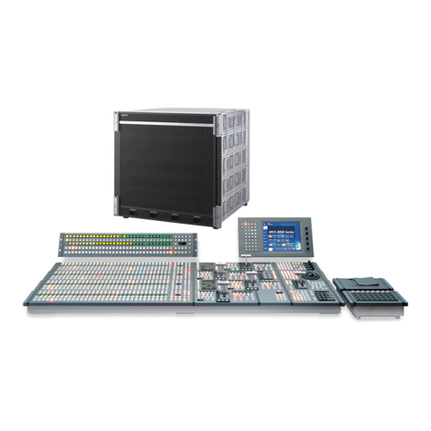
Sony MVS-8000 User manual

Sony

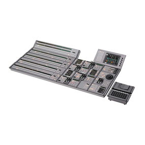
Sony MVS-8000 User manual

Sony G363-ZR0-LAX1 User manual

Sony

Sony G363-ZR0-LAX1 User manual

Sony DVS-7000A User manual

Sony

Sony DVS-7000A User manual

Sony DVS-9000 User manual

Sony

Sony DVS-9000 User manual

Sony SB-V60S - Auto Switcher AV Selector User manual

Sony

Sony SB-V60S - Auto Switcher AV Selector User manual

Sony MVS-8000 User manual

Sony

Sony MVS-8000 User manual

Sony CCP-8000 Series User manual

Sony

Sony CCP-8000 Series User manual

Sony XVS Series User manual

Sony

Sony XVS Series User manual

Sony XKS-C9111 User manual

Sony

Sony XKS-C9111 User manual

Sony PCGA-PRFX1 User manual

Sony

Sony PCGA-PRFX1 User manual

Sony MVS-3000 System User manual

Sony

Sony MVS-3000 System User manual

Sony XVS-G1 User manual

Sony

Sony XVS-G1 User manual

Sony DVS-V3232M User manual

Sony

Sony DVS-V3232M User manual

Sony SB-V900 User manual

Sony

Sony SB-V900 User manual

Sony MHC-5500 User manual

Sony

Sony MHC-5500 User manual

Sony XA-C30 - 2 Output Selector User manual

Sony

Sony XA-C30 - 2 Output Selector User manual

Sony 26-483-01 Instruction manual

Sony

Sony 26-483-01 Instruction manual

Sony HKS-5810M User manual

Sony

Sony HKS-5810M User manual

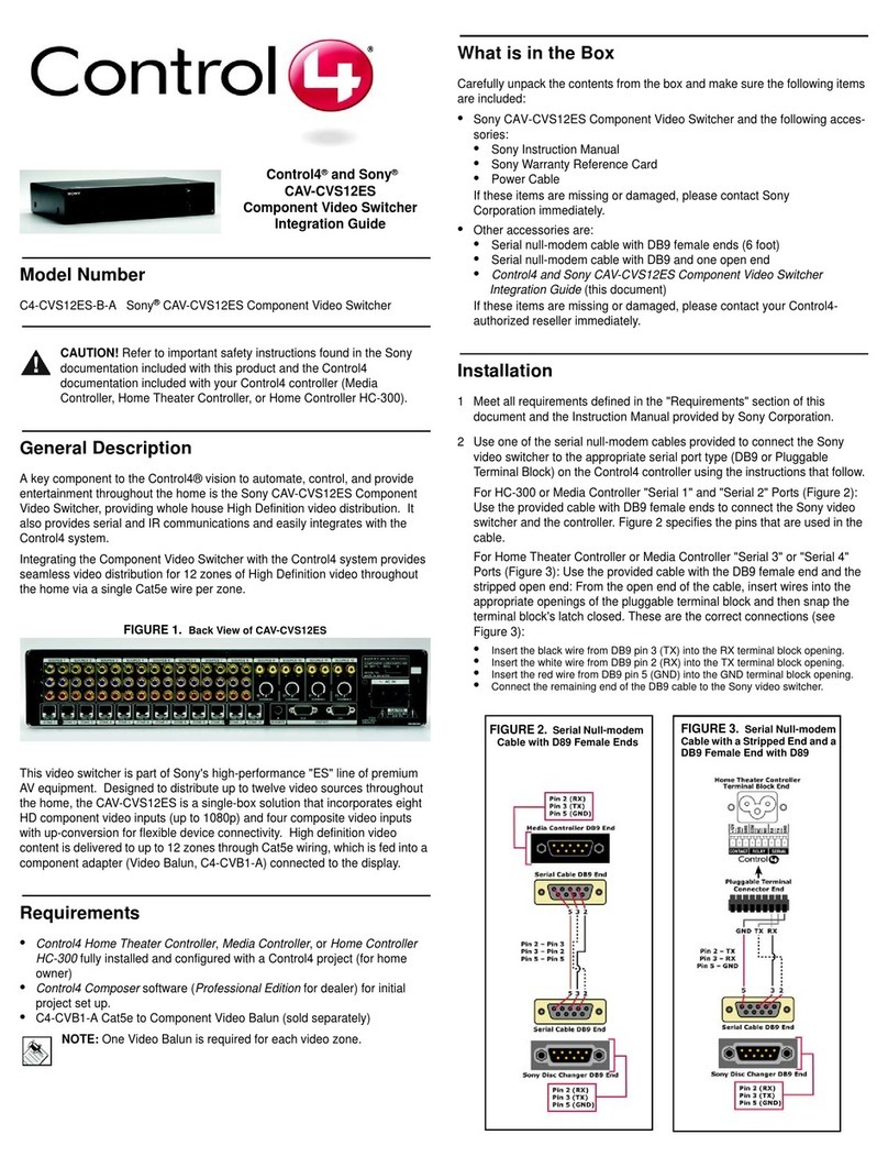
Sony CAV-CVS12ES - Component Video Switcher User manual

Sony

Sony CAV-CVS12ES - Component Video Switcher User manual

Sony DVS-9000 User manual

Sony

Sony DVS-9000 User manual

Sony BVS-3200CP User manual

Sony

Sony BVS-3200CP User manual

Sony MVS-6000 User manual

Sony

Sony MVS-6000 User manual

Sony BRS-200 User manual

Sony

Sony BRS-200 User manual

Sony XA-U40D User manual

Sony

Sony XA-U40D User manual

Popular Switch manuals by other brands

Vantec UGT-AH710U3-BK installation guide

Vantec

Vantec UGT-AH710U3-BK installation guide

Blue Sea Systems ML Series installation instructions

Blue Sea Systems

Blue Sea Systems ML Series installation instructions

Aube Technologies TI033 Installation and user guide

Aube Technologies

Aube Technologies TI033 Installation and user guide

Aurora DXE-122A user guide

Aurora

Aurora DXE-122A user guide

Dwyer Instruments FLOTECT V6 series Installation and operating instructions

Dwyer Instruments

Dwyer Instruments FLOTECT V6 series Installation and operating instructions

3Com S7906E - Switch datasheet

3Com

3Com S7906E - Switch datasheet

Helwett Packard 8325P Installation, Safety, and Regulatory Information

Helwett Packard

Helwett Packard 8325P Installation, Safety, and Regulatory Information

Intermatic ET8000 Series Installation and user instructions

Intermatic

Intermatic ET8000 Series Installation and user instructions

HP FlexNetwork 7500 Series Command reference

HP

HP FlexNetwork 7500 Series Command reference

Conrad 91 79 13 operating instructions

Conrad

Conrad 91 79 13 operating instructions

Belkin F1DN104C-3 user manual

Belkin

Belkin F1DN104C-3 user manual

gofanco HDRswitch5P user guide

gofanco

gofanco HDRswitch5P user guide

Airlinkplus AKVM-2 Quick installation guide

Airlinkplus

Airlinkplus AKVM-2 Quick installation guide

ATEN Slideaway CL5708 specification

ATEN

ATEN Slideaway CL5708 specification

Zinwell WB68 installation guide

Zinwell

Zinwell WB68 installation guide

AsGa LightBolt 28322-O1 user guide

AsGa

AsGa LightBolt 28322-O1 user guide

IMC Networks PD-Switch features and benefits

IMC Networks

IMC Networks PD-Switch features and benefits

StarTech.com IES81GW Start guide

StarTech.com

StarTech.com IES81GW Start guide

manuals.online logo
manuals.online logoBrands
  • About & Mission
  • Contact us
  • Privacy Policy
  • Terms and Conditions

Copyright 2025 Manuals.Online. All Rights Reserved.