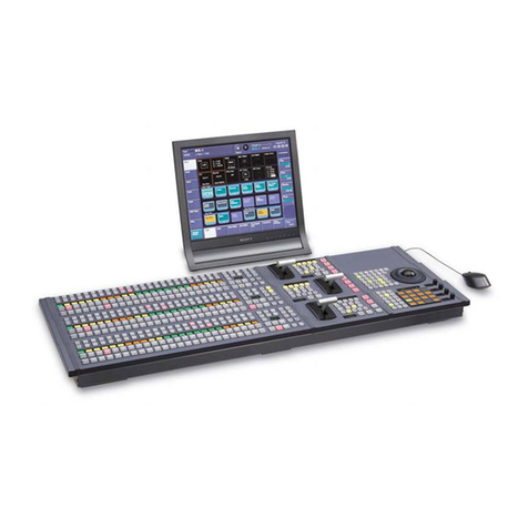
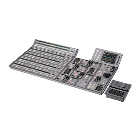
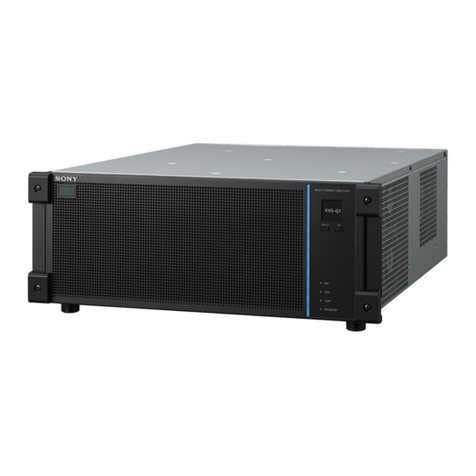
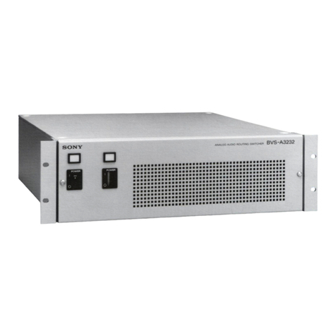
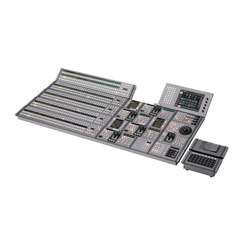
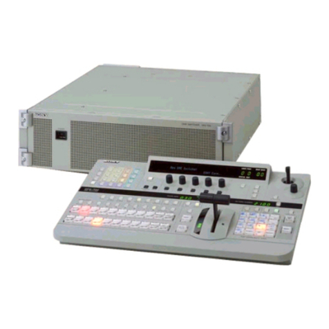
Sony DVS-2000C User manual

DIGITAL VIDEO SWITCHER
DVS-2000C
SWITCHER CONTROL PANEL
INSTALLATION MANUAL
1st Edition
BKDS-2010
BZS-2010 BZS-2020 BZS-2090 BKDS-2020
BKDS-2021 BKDS-2022 BKDS-2031 BKDS-2032
BKDS-2041 BKDS-2050 BKDS-2060 BKDS-2061
BKDS-2062 BKDS-2070 BKDS-2071 BKDS-2072

SAFETY CHECK-OUT
After correcting the original service problem, perform
the following safety checks before releasing the set
to the customer:
Check the metal trim, “metallized” knobs, screws,
and all other exposed metal parts for AC leakage.
Check leakage as described below.
LEAKAGE TEST
The AC leakage from any exposed metal part to
earth ground and from all exposed metal parts to any
exposed metal part having a return to chassis, must
not exceed 3.5 mA. Leakage current can be
measured by any one of three methods.
1. A commercial leakage tester, such as the
Simpson 229 or RCA WT-540A. Follow the
manufacture’s instructions to use these
instruments.
2. A battery-operated AC milliammeter. The Data
Precision 245 digital multimeter is suitable for
this job.
3. Measuring the voltage drop across a resistor by
means of a VOM or battery-operated AC
voltmeter. The “limit” indication is 5.25 V so
analog meters must have an accurate low-
voltage scale. The Simpson 250 and Sanwa SH-
63Trd are examples of a passive VOM that is
suitable. Nearly all battery operated digital
multimeters that have a 20 V AC range are
suitable (see Fig. A).
ToExposedMetal
PartsonSet
0.15µF
EarthGround
1.5kΩAC
voltmeter
(5.25V)
Fig. A. Using an AC Voltmeter to check AC leakage.
DVS-2000C Serial No. 10001 and
Higher
BZS-2010 Serial No. 10001 and
Higher BZS-2020 Serial No. 10001
and Higher BZS-2090 Serial No. 10001
and Higher BKDS-2010 Serial No.
10001 and Higher BKDS-2020 Serial
No. 10001 and Higher BKDS-2021
Serial No. 10001 and Higher
BKDS-2022 Serial No. 10001 and
Higher BKDS-2031 Serial No.
10001 and Higher
BKDS-2032 Serial No. 10001 and
Higher
BKDS-2041 Serial No. 10001 and
Higher
BKDS-2050 Serial No. 10001 and
Higher
BKDS-2060 Serial No. 10001 and
Higher
BKDS-2061 Serial No. 10001 and
Higher
BKDS-2062 Serial No. 10001 and
Higher
BKDS-2070 Serial No. 10001 and
Higher
BKDS-2071 Serial No. 10001 and
Higher
BKDS-2072 Serial No. 10001 and
Higher

VORSICHT
Um Feuergefahr und die Gefahr eines elektrischen
Schlages zu vermeiden, darf das Gerät weder Regen
noch Feuchtigkeit ausgesetzt werden.
Um einen elektrischen Schlag zu vermeiden, darf das
Gehäuse nicht geöffnet werden. Überlassen Sie
Wartungsarbeiten stets nur einem Fachmann.
Bescheinigung des Herstellers / Importeurs
Hiermit wird bescheinigt, daß die Digital-Video-
Schalteinheit DVS-2000C in Übereinstimmung mit den
Bestimmungen der BMPT-Amtsblatt Vfg 243/1991 und
Vfg 46/1992 funkentstört ist. Der vorschriftsmäßige
Betrieb mancher Geräte (z.B. Meßsender) kann
allerdings gewissen Einschränkungen unterliegen.
Beachten Sie deshalb die Hinweise in der
Bedienungsanleitung. Dem Bundesamt für Zulassungen
in der Telekommunikation wurde das Inverkehrbringen
dieses Gerätes angezeigt und die Berechtigung zur
Überprüfung der Serie auf die Einhaltung der
Bestimmungen eingeräumt.
Sony Deutschland GmbH
Hugo Eckener Str. 20
50829 Köln
Hinweis
Gemäß der Amtsblätter des BMPT Nrn. 61/1991 und 6/
1992 wird der Betreiber darauf aufmerksam gemacht,
daß die von ihm mit diesem Gerät zusammengestellte
Anlage auch den technischen Bestimmungen dieser
Amtsblätter genügen muß.
For the customers in the United Kingdom
WARNING
THIS APPARATUS MUST BE EARTHED
IMPORTANT
The wires in this mains lead are coloured in accordance
with the following code:
Green-and-yellow: Earth
Blue: Neutral
Brown: Live
As the colours of the wires in the mains lead of this
apparatus may not correspond with the coloured
markings identifying the terminals in your plug proceed
as follows:
The wire which is coloured green-and-yellow must be
connected to the terminal in the plug which is marked
by the letter E or by the safety earth symbol or
coloured green or green-and-yellow.
The wire which is coloured blue must be connected to
the terminal which is marked with the letter N or
coloured black.
The wire which is coloured brown must be connected
to the terminal which is marked with the letter L or
coloured red.
WARNING
To prevent fire or shock hazard, do
not expose the unit to rain or
moisture.
To avoid electrical shock, do not open
the cabinet. Refer servicing to
qualified personnel only.
For the customers in the USA
This equipment has been tested and found to comply
with the limits for a Class A digital device, pursuant to
Part 15 of the FCC Rules. These limits are designed to
provide reasonable protection against harmful
interference when the equipment is operated in a
commercial environment. This equipment generates,
uses, and can radiate radio frequency energy and, if not
installed and used in accordance with the instruction
manual, may cause harmful interference to radio
communications. Operation of this equipment in a
residential area is likely to cause harmful interference in
which case the user will be required to correct the
interference at his own expense.
You are cautioned that any changes or modifications not
expressly approved in this manual could void your
authority to operate this equipment.
The shielded interface cable recommended in this
manual must be used with this equipment in order to
comply with the limits for a digital device pursuant to
Subpart B of Part 15 of FCC Rules.
WARNING
If used in USA, use the UL LISTED power cord specified
below. DO NOT USE ANY OTHER POWER CORD.
Plug Cap Parallel blade with ground pin
(NEMA 5-15P Configuration)
Cord Type SJT, three 16 or 18 AWG wires
Length Less than 2.5 m (8 ft 3 in)
Rating Minimum 10 A, 125 V
Using this unit at a voltage other than 120 V may require
the use of a different line cord or attachment plug, or
both. To reduce the risk of fire or electric shock, refer
servicing to qualified service personnel.
For the customers in Canada
This apparatus complies with the Class A limits for radio
noise emissions set out in Radio Interference
Regulations.
Pour les utilisateurs au Canada
Cet appareil est conforme aux normes Classe A pour
bruits radioélectriques, spécifiés dans le Règlement sur
le brouillage radioélectrique.
This symbol is intended to alert the
user to the presence of important
operating and maintenance
(servicing) instructions in the
literature accompanying the
appliance.
DVS-2000Cスイッチャーシステムのプロセッサー部である
デジタルビデオスイッチャーDVS-2000Cと、これを制御す
るためのスイッチャーコントロールパネルBKDS-2010を操
作するには、それぞれ下記のマニュアルが必要です。
DVS-2000Cインストレーションマニュアル
(このマニュアルです。スイッチャーに付属しています。)
第1章「取り扱い操作」では、DVS-2000Cシステムおよび別
売り品の概要、スイッチャーの各部の働き、接続例などを
記載しています。ビデオスイッチャーシステム全体を管理
される方は、この章を最初にお読みください。
第2章以降では、システムの設置に必要な情報を記載してい
ます。
DVS-2000CメンテナンスマニュアルPart1
(スイッチャーに付属しています。)
スイッチャーシステムの保守、点検に必要な情報を記載し
ています。スイッチャーのメンテナンスが必要になったと
きや、何らかの異常が発生したときにご覧ください。
BZS-2010ユーザーガイド
(別売りのソフトウェアに付属しています。)
コントロールパネルの各部の働きと、スイッチャーの操作
方法を記載しています。スイッチャーを操作するときにご
覧ください。
BKDS-2010メンテナンスマニュアルPart2
コントロ−ルパネルのハ−ドウェアに関する情報を記載し
ています。
DVS-2000CメンテナンスマニュアルPart2
(別売り)
スイッチャーのハードウェアに関する情報を記載していま
す。
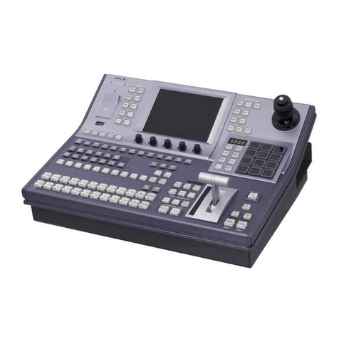
The DVS-2000C Digital Video Switcher System is made
up of the DVS-2000C Video Switcher, which forms the
processor component, and the BKDS-2010 Switcher
Control Panel. The following manuals are necessary to
operate these two units.
DVS-2000C Installation Manual
(This manual, supplied with the switcher)
Section 1, “Operation” gives an overview of the BVS-
2000C system and optional accessories, explains the
function of parts for the switcher, and gives connection
examples. Persons responsible for management of the
system are required to read this section first. The second
and following sections contain information needed for
installation.
DVS-2000C Maintenance Manual Part 1
(Supplied with the switcher)
Contains information needed for periodic maintenance.
Read this manual when maintenance is necessary, or
when trouble develops.
BZS-2020 User’s Guide
(Supplied with operation software)
Explains operation procedures and function of each part
of the control panel. Read this manual before operating
the control panel.
BKDS-2010 Maintenance Manual
Contains information about the hardware of the control
panel.
DVS-2000C Maintenance Manual Part 2
Contains information about the hardware of the proces-
sor.
DVS-2000Cデジタルビデオスイッチャーシステムのマニュアルについて
About the Manuals for the DVS-2000C Digital Video Switcher

オペレーションソフトウェアバージョン1.10用別売り品について
Optional Accessories for ver. 1.10 operation software
オペレーションソフトウェアのバージョンが1.10以降の
DVS-2000Cに対しては、以下の別売り品をご使用くださ
い。
スイッチャーコントロールパネルBKDS-2010/1(シリアル
ナンバー20001以降)
プログラムメモリー容量を、従来の1Mビットから4Mビッ
トに拡張しました。本マニュアルでは、BKDS-2010(シリア
ルナンバー10001〜10140)とBKDS-2010/1を併せて
BKDS-2010と呼んでいます。DVS-2600/2600Cに対し
ては、BKDS-2010もご使用になれます。
シリアルデジタルインプットボードBKDS-2020A/2021A
BKDS-2020/2021の機能に加えて、DME-3000などからのデ
プスキー信号の入力を可能にしました。本マニュアルで
は、BKDS-2020/2020Aを併せてBKDS-2020、BKDS-
2021/2021Aを併せてBKDS-2021と呼んでいます。
メモリーパックBZS-2090A
保存できるスナップショットの数を、BZS-2090の約25個か
ら約99個まで拡張しました。ただし、DVS-2000CにCPU
アップグレードボードBKDS-2072を組み込んでいない場合
は、メモリー数は増えません。本マニュアルでは、BZS-
2090/2090Aを併せてBZS-2090と呼んでいます。
For a DVS-2000C with ver. 1.10 or later operation
software, use the following optional accessories.
BKDS-2010/1 Switcher Control Panel (Serial No.
20001 or higher)
Program memory has been expanded to 4 megabits from
the 1 megabits of the previous model. This manual uses
“BKDS-2010” to refer to both the BKDS-2010 (Serial
Nos. 10001 through 10140) and BKDS-2010/1. For the
DVS-2100C, you can use the BKDS-2010.
BKDS-2020A/2021A Serial Digital Input board
In addition to the functions provided by the BKDS-2020/
2021, supports input of depth key signals from the DME-
3000 and other units. This manual uses “BKDS-2020” to
refer to both the BKDS-2020 and BKDS-2020A, and
“BKDS-2021” to refer to both the BKDS-2021 and
BKDS-2021A.
BZS-2090A Memory Pack
The BZS-2090A allows you to store about 99 snapshots,
compared to the limit of about 25 snapshots for the BZS-
2090. However, the expanded memory is not available
unless you have installed the BKDS-2072 CPU Upgrade
Board in the DVS-2000C. This manual uses “BZS-2090”
to refer to both the BZS-2090 and the BZS-2090A.

目 次
TABLE OF CONTENTS
1. 取り扱い操作...................................................... 1-1(J)
1-1DVS-2600の概要............................................. 1-1(J)
1-1-1 主な特長 ........................................................1-1(J)
1-1-2 別売り品 ........................................................1-3(J)
1-1-3 周辺機器の構成 .............................................1-6(J)
1-1-4 使用上のご注意 .............................................1-8(J)
1-2各部の名称と働き ............................................ 1-9(J)
1-2-1 前面パネルと内部 .........................................1-9(J)
1-2-2 後面パネル ..................................................1-16(J)
1-2-3 コントロールパネル
BKDS-6010(別売り)後面 .......................1-20(J)
1-2-4 ROMPACKおよびMEMORYPACK
(BZS-2090、別売り)の使用方法 ..............1-21(J)
1-3システム構成例 .............................................. 1-22(J)
1-3-1 コントロールパネルとの接続 ....................1-22(J)
1-3-2 プライマリー入力とビデオモニター
との接続 ......................................................1-23(J)
1-3-3 外部クロマキーソースとの接続.................1-24(J)
1-3-4 デジタルマルチエフェクトDME-5000
との接続 ......................................................1-25(J)
1-3-5 エディティングコントロールシステム
BVE-2000との接続 .....................................1-26(J)
1-4仕様 ............................................................. 1-27(J)
1-4-1 デジタルビデオスイッチャーDVS-2600....1-27(J)
1-4-2 BKDS-2010SWITCHERCONTROL
PANEL ........................................................1-33(J)
1-4-3 BKDS-2610/2611SYNCGENERATOR
BOARD(FORCOMPOSITE/
COMPONENTVERSION) .......................1-33(J)
1-4-4 BKDS-8021ANALOGINPUTBOARD....1-34(J)
1-4-5 BKDS-8022DIGITALINPUTBOARD ....1-35(J)
1-4-6 BKDS-8030CLEANCHROMAKEY
BOARD .......................................................1-35(J)
1-4-7 BKDS-8031CLEANCHROMAKEY
BOARD .......................................................1-36(J)
1-4-8 BKDS-8040FRAMEMEMORY
BOARD .......................................................1-36(J)
1-4-9 BKDS-8041FRAMEMEMOERY
BOARD .......................................................1-36(J)
1-4-10 BKDS-6060DIGITALEDITPVW/REF
OUTPUTBOARD ......................................1-37(J)
1-4-11 BKDS-6061ANALOGEDITPVW/REF
OUTPUTBOARD ......................................1-37(J)
1-4-12 BKDS-6062ANALOGEDITPVW/REF
OUTPUTBOARD ......................................1-38(J)
1-4-13 BKDS-6063DIGITALOUTPUT
BOARD .......................................................1-39(J)
1-4-14 BKDS-6064ANALOGOUTPUT
BOARD .......................................................1-38(J)
1-4-15 BKDS-6071KEYBORDERGENERATOR
BOARD .......................................................1-40(J)
1-4-16 BKDS-6072BKDGCOLORMIX
GENERATORBOARD..............................1-40(J)
1-4-17 BKDS-6073M/EPVWOPTION..............1-40(J)
1-4-18 BKDS-6090SPAREPOWERSUPPLY
UNIT............................................................1-41(J)
1-4-19 BZS-2090MEMORYPACK ......................1-41(J)

1. OPERATION.............................................1-1(E)
1-1 Overview of the DVS-6000/6000C....... 1-1(E)
1-1-1 Principal Features ......................... 1-1(E)
1-1-2 Optional Accessories .................... 1-3(E)
1-1-3 Peripheral Equipment
Configuration................................ 1-5(E)
1-1-4 Important Precautions ................... 1-7(E)
1-2 Location and Function of Parts ........... 1-8(E)
1-2-1 Front Panel and Interior................. 1-8(E)
1-2-2 Rear Panel ................................... 1-15(E)
1-2-3 BKDS-6010 Control
Panel (optional) rear panel .......... 1-19(E)
1-3 System Configuration Examples....... 1-20(E)
1-3-1 Control Panel Connections.......... 1-20(E)
1-3-2 Primary Input and Video Monitor
Connections ................................ 1-21(E)
1-3-3 External Chroma Key Source
Connections ................................ 1-22(E)
1-3-4 DME-5000 Digital Multi Effect
Connections ................................ 1-23(E)
1-3-5 BVE-9100 Editing Control System
Connections ................................ 1-24(E)
1-4 Specifications...................................... 1-25(E)
1-4-1 DVS-6000/6000C ....................... 1-25(E)
1-4-2 BKDS-6010 ................................ 1-30(E)
1-4-3 BKDS-8021 ................................ 1-31(E)
1-4-4 BKDS-8022 ................................ 1-32(E)
1-4-5 BKDS-8030 ................................ 1-32(E)
1-4-6 BKDS-8031 ................................ 1-33(E)
1-4-7 BKDS-8040 ................................ 1-33(E)
1-4-8 BKDS-8041 ................................ 1-33(E)
1-4-9 BKDS-6050 ................................ 1-34(E)
1-4-10 BKDS-6060 ................................ 1-34(E)
1-4-11 BKDS-6061 ................................ 1-35(E)
1-4-12 BKDS-6062 ................................ 1-35(E)
1-4-13 BKDS-6063 ................................ 1-36(E)
1-4-14 BKDS-6064 ................................ 1-36(E)
1-4-15 BKDS-6070 ................................ 1-37(E)
1-4-16 BKDS-6071 ................................ 1-37(E)
1-4-17 BKDS-6072 ................................ 1-38(E)
1-4-18 BKDS-6090 ................................ 1-38(E)

第1章 取り扱い操作
Section 1 OPERATION 1-1
第1章 取り扱い操作
Section 1 OPERATION
1-1 DVS-2000Cの概要
デジタルビデオスイッチャーDVS-2000Cは、放送局やポス
トプロダクションハウスでの小規模コンポーネントデジタ
ル編集システムや、ENG、OBバン等への幅広い用途に対
応できる高性能スイッチャーです。スイッチャーの操作
は、主として別売りのコントロールパネルBKDS-2010から
行います。
なお、この第1章では各機器を次のように呼びます。
第1章 取り扱い操作 Section1 OPERATION
1)Flexi Padはソニー株式会社の商標です。 1) Flexi Pad is a trademark of Sony Corporation.
1-1 Overview of the DVS-2000C
The DVS-2000C Digital Video Switcher is a high-perfor-
mance digital switcher that enables broadcasting stations
and production houses to construct small-scale component
digitalediting systems. It isalso suited to use in ENG (elec-
tronic news gathering) and a wide variety of other applica-
tions.Most switcher operationsarecarriedoutusing the op-
tionalBKDS-2010SwitcherControlPanel.Thissectionwill
use the following terms for the components of the system.
機器の正式名称/Full name 本マニュアルでの呼びかた/Terms used in this manual
デジタルビデオスイッチャーDVS-2000C
DVS-2000C Digital Video Switcher
スイッチャーコントロールパネルBKDSー2010
BKDS-2010 Switcher Control Panel
スイッチャー/Switcher
コントロールパネル/Control panel
1-1-1 主な特長
新開発LSIによる小型化、省電力化
新開発の大規模LSIの採用により、スイッチャーの小型化と
消費電力の低減化を実現しました。
マンマシンインターフェースを考慮したコントロールパ
ネル
19インチ幅の小型のコントロールパネルながら、LCDディ
スプレイやFlexi Pad™1)の採用により、マンマシンイン
ターフェースを十分考慮した、シンプルで使いやすいパネ
ルとなっています。
高機能かつ拡張可能な入出力インターフェース
プライマリー入力部は、別売りのアナログコンポーネント
入力基板またはアクティブループスルー出力付きのシリア
ルデジタル入力基板の組み込みにより、最大16チャンネル
まで増設できます。入力された信号は、すべてバックグラ
ウンド、キーフィル、キーソースとして使用できます。
TBC(Time Base Corrector)機能がチャンネルごとに装
備されているため、各入力信号について位相を調整し、
ジッターを除去することができます。さらに、ビデオプロ
セッシング機能をチャンネルごとに装備しているため、ゲ
イン、オフセット、色相などを各入力信号で個別に調整で
きます。
1-1-1 Features
Low power consumption and compact size
Many switcher function have been realized in newly
developed VLSIs, for low power consumption and
compact size.
Easy-to-use control panel
The easy-to-use control panel, only 19 inches in width,
provides a simple and well-designed man/machine
interface, with features such as an LCD display and a
Flexi Pad™1).
High-performance, expandable I/O interface
Primary inputs can be expanded to 16 channels by
installing optional analog component input boards, or
serial digital input boards with active loop through
output. All input signals can be used as background, key
fill and key source. Each channel is provided with a TBC
(time base corrector) function, allowing you to adjust
signal phase and remove jitter. Video processing func-
tions are also provided for every channel, allowing you to
adjust the gain, offset, and chrominance of each input
signal.

1-2 第1章 取り扱い操作
Section 1 OPERATION
第1章 取り扱い操作
Section 1 OPERATION
第1章 取り扱い操作
Section 1 OPERATION
There are three program output channels and one edit
preview output channel (AUX4) as standard. An assign-
able output board is available to provide one channel of
analog component output and two channels of serial
digital output, each of which can be used independently.
An optional auxiliary output board is also available to
provide three AUX bus output channels.
High-definition, high-quality key effects
The switcher is equipped with two keyer channels,
expandable to three channels through installation of
optional DSK boards.
The keyers guarantee high-definition, high-quality key
effects through fine adjustment of key edge position on a
sub-clock basis (FineKey™1) function) and
oversampling. An optional chroma key board provides
similar effects (FineChroma™ 2) function). Optional
border generators are available for continuous adjustment
of borders, drop borders,
shadows, and outlines, using modifiers such as edging
color, position, width, hue and softness.
Newly developed VLSIs expand key signals to the word
length needed for internal processing, reducing
degradation in signal characteristics.
Variety of new functions
Dynamic priority control: Allows continuous
modification of KEY1 and KEY2 priority with the
fader lever and encoder knob.
Depth key processing: Allows exchange of depth key
signal with the DME-3000 or other digital multi
effects units.
Processed key output: Allows efficient exchange of
chroma key signals and key signals containing
modifier information with the DME-3000 or other
digital multi effects units.
DME-Link®3):Allows control of both the switcher and
the DME-3000 or other digital multi effects units
from the control panel.
出力部には、PGMを3チャンネルとEDIT PVWを1チャン
ネル(AUX4として)標準装備しています。別売りのアサイナ
ブル出力基板の組み込みにより、1チャンネルのアナログコ
ンポーネント出力と2チャンネルのシリアルデジタル出力
を、それぞれ異なる目的に個別に使用できます。また、別
売りのAUX出力基板の組み込みにより、AUXバスを3チャン
ネル使用できます。
高品位・高画質キー
標準で2チャンネルのキーヤーを装備していますが、別売り
のDSK基板の組み込みによりさらにキーヤーを1チャンネル
増設できます。
これらのキーヤーでは、キーエッジをサブクロック単位で
連続可変調整する機能(FineKey™1)機能)やオーバーサン
プリング処理等により、高品位・高画質のキーが得られま
す。また、別売りのクロマキー基板にも同様の機能が搭載
されています(FineChroma™2)機能)。また、別売りのボー
ダージェネレーター基板の組み込みにより、ボーダー、ド
ロップボーダー、シャドウ、アウトラインなどのモディ
ファイヤーとして、キーエッジの色相、位置、幅、濃さ、
ソフトネスを連続的に可変することができます。
さらに、新開発の大規模LSIによりキー信号を必要語長に拡
張して処理できるため、信号の特性劣化が小さくなってい
ます。
豊富な機能
ダイナミックプライオリティコントロール:フェーダーレ
バーやエンコーダーつまみによる、KEY1とKEY2間の
プライオリティの連続可変が可能。
デプスキープロセッシング:DME-3000などのデジタルマ
ルチエフェクトと、デプスキー信号のやり取りが可
能。
プロセストキー出力:DME-3000などのデジタルマルチエ
フェクトと、クロマキー信号や修飾機能を含むキー信
号の効率的なやり取りが可能。
DME-Link® 3):コントロールパネルから、DME-3000など
の
デジタルマルチエフェクト
と
スイッチャー
の両方を制
御。
1) FineKeyはソニー株式会社の商標です。
2) FineChromaはソニー株式会社の商標です。
3) DME-Linkはソニー株式会社の登録商標です。
1) FineKey is a trademark of Sony Corporation.
2) FineChroma is a trademark of Sony Corporation.
3) DME-Link is a registered trademark of Sony Corporation.

第1章 取り扱い操作
Section 1 OPERATION 1-3
第1章 取り扱い操作
Section 1 OPERATION
FineChroma:別売りのクロマキー基板の組み込みによ
り、次の機能が実現できます。
•4:4:4入力
•オーバーサンプリング
•デュアル調整
•カラーモディフィケーション
•シャドウ制御
•専用マスクジェネレーター
幅広いオプション
ビデオおよびキー信号の入/出力基板に加えて、作成したビ
デオおよびキー信号や、ペン・タブレットで作成したマス
クパターンを蓄積するためのフレームメモリー基板、エン
ハストワイプパターン(ハート、スター、マトリックスパ
ターンなど)を使用するためのエンハンストワイプジェネ
レーター基板、CPUアップグレード基板などの別売り基板
が用意されています。また、スイッチャーのセットアップ
データや作成したスナップショットデータを保存するため
のメモリーパックも、別売り品として用意されています。
高いシステム拡張性
525ˆ625ラインモードの切り換えや、4:3ˆ16:9のアス
ペクト比の切り換えをメニュー画面で行えるため、システ
ム変更への対応が容易です。
後面パネルには、BVE-2000などのエディティングコント
ロールシステムやデジタルマルチエフェクトの接続用イン
ターフェースを標準装備しています。別売りのCPUアップ
グレード基板の組み込みにより、外部マトリックススイッ
チャーの接続用インターフェースが使用できるようになる
ため、高度な編集作業が可能になります。また、シリアル
タリー端子、ターミナル端子を標準装備しているため、さ
まざまな外部機器を必要に応じて接続できます。
容易なメンテナンス
万一の故障などによるロスタイムを短縮するため、電源、
回路基板など主要部分に対しては、キャビネット前面から
保守作業を行えるように配慮しています。また、回路調整
機能や設定機能の多くをソフトウェアでサポートすること
により、調整ボリュームやスイッチ類の個数を最小限に抑
えています。
スイッチャー内部の自己診断機能を装備しているほか、ISR
(Interactive Status Reporting)対応により、システム全体の
故障診断をサポートできます。
FineChroma: Installation of an optional chroma key
board provides the following functions.
•4:4:4 input
•Oversampling
•Dual adjustment
•Color modification
•Shadow adjustment
•Exclusive mask generators
Optional functions
In addition to optional I/O interface boards, numerous
optional boards are available to increase the flexibility of
the system, including an enhanced wipe generator board
to provide heart, star, matrix and other wipe patterns, a
CPU upgrade board, and a frame memory board to store
key signals and video created with the system as well as
mask patterns created with the pen tablet. Optional
memory packs provide increased memory for storage of
switcher setup data and snapshot data.
Flexible system configuration
The setup menu allows you to configure the system by
switching between 525-line and 625-line modes, or
between 4:3 and 16:9 aspect ratios.
You can connect editing control system such as the BVE-
2000 and digital multi effects units using interface on the
rear panel. An optional CPU upgrade board is available to
provide an interface to external matrix switchers for
sophisticated editing operations. Standard connectors for
serial tally and terminal units allow you to connect a wide
variety of external devices as necessary.
Easy maintenance
The power supply, circuit boards, and other principal
components are accessible from the front of the cabinet,
for easy maintenance and shorter down time in the event
of a malfunction. The number of switches and controls
has been held to a minimum, using software control as far
as possible for circuit adjustments and settings. The
switcher is equipped with internal self-diagnostic func-
tions and supports Interactive Status Reporting (ISR),
providing a quick overview of the state of the switcher.

1-4 第1章 取り扱い操作
Section 1 OPERATION
第1章 取り扱い操作
Section 1 OPERATION
第1章 取り扱い操作
Section 1 OPERATION
1-1-2 別売り品
BKDS-2010 SWITCHER CONTROL PANEL(スイッ
チャーコントロールパネル)
DVS-2000Cの動作を制御するためのコントロールパネル
です。
専用のオペレーションソフトウェアBZS-2010が必要です。
BKDS-2020 6 SERIAL DIGITAL INPUT BOARD(6チャ
ンネルシリアルデジタルインプットボード)
D1シリアルデジタル信号を入力するための基板です。6
チャンネルのビデオまたはキー信号を入力することができ
ます。各チャンネルに、TBC機能、ビデオプロセッシング
機能、アクティブループスルー出力を備えています。ス
イッチャーに最大2枚まで組み込めます。
BKDS-2021 2 SERIAL DIGITAL INPUT BOARD(2チャ
ンネルシリアルデジタルインプットボード)
D1シリアルデジタル信号を入力するための基板です。2
チャンネルのビデオまたはキー信号を入力することができ
ます。各チャンネルに、TBC機能、ビデオプロセッシング
機能、ループスルー出力を備えています。アナログコン
ポーネントインプットボードBKDS-2022に1枚装着できま
す。
BKDS-2022 ANALOG COMPONENT INPUT BOARD
(アナログコンポーネントインプットボード)
アナログコンポーネント信号を入力するための基板です。
各2チャンネルのビデオ信号(Y/B−Y/R−Y)およびキー信
号(KEY)を入力することができます。各チャンネルに、
TBC機能とビデオプロセッシング機能を備えています。ス
イッチャーに最大2枚まで組み込めます。
BKDS-2031 CHROMAKEY BOARD(クロマキーボード)
クロマキー機能を使うための基板です。フォアグラウンド
信号とバックグラウンド信号入力が4:2:2のクロマキーに
加えて、フォアグラウンド信号入力が4:4:4(Y/B−Y/R−
Y)の場合にも対応できます。またビデオプロセッシング機
能も備えています。
1-1-2 Optional Accessories
BKDS-2010 Switcher Control Panel
Control panel for the DVS-2000C.
BZS-2020 Operation Software is needed to operate the
control panel.
BKDS-2020 6 Serial Digital Input Board
Provides input of D1 serial digital signals to the DVS-
2000C. Up to six channels of video or key signals can be
input. Each channel is equipped with functions for TBC,
video processing and active loop-through output. Up to
two BKDS-2020 boards can be installed in the switcher.
BKDS-2021 2 Serial Digital Input Board
Provides input of D1 serial digital signals to the DVS-
2000C. Up to two channels of video or key signals can be
input. Each channel is equipped with functions for TBC,
video processing and active loop-through output. One
BKDS-2021 board can be installed in the switcher
together with a BKDS-2022 Analog Component Input
Board.
BKDS-2022 Analog Component Input Board
Provides input of analog component signals to the DVS-
2000C. Up to two channels of video (Y/B–Y/R–Y) and
key (KEY) signals can be input. Each channel is
equipped with functions for TBC and video processing.
active loop-through output. Up to two BKDS-2022
boards can be installed in the switcher.
BKDS-2031 Chromakey Board
Provides chroma key functions for the DVS-2000C.
Supports 4:2:2 foreground and background chroma key
signals, and 4:4:4 (Y/B–Y/R–Y) foreground signals.
Also provides a video processing function.

第1章 取り扱い操作
Section 1 OPERATION 1-5
第1章 取り扱い操作
Section 1 OPERATION
BKDS-2032CHROMAKEYUPGRADEBOARD(クロマ
キーアップグレードボード)
クロマキーボードBKDS-2031の性能をさらに高めるための
基板です。フォアグラウンド信号、バックグラウンド信号
入力がともに4:4:4(Y/B−Y/R−Y)の場合にも対応でき
るようになります。また、デュアル調整、
カラーモディフィ
ケーション
、シャドウ制御などの機能が使えるようになりま
す。クロマキーボードBKDS-2031に1枚装着できます。
BKDS-2041 FRAME MEMORY BOARD(フレームメモ
リーボード)
フレームメモリー機能を使うための基板です。1フレーム×
2チャンネル分のメモリー容量があり、ビデオ信号やキー信
号を記憶します。専用のマスクジェネレーター、マット
ジェネレーター、ペン・タブレット用のインターフェース
を備えています。
BKDS-2050 DSK WITH BORDER/FINEKEYBOARD
(DSKウィズボーダー/ファインキーボード)
ダウンストリームキーヤー機能を使うための基板です。
KEY1、KEY2と同等のキー機能に加えて、マスクジェネ
レーターとボーダー機能を備えています。
BKDS-2060ASSIGNABLEOUTPUTBOARD(アサイナブ
ルアウトプットボード)
アサイナブル出力を使うための基板です。2チャンネルのシ
リアルデジタル出力と、1チャンネルのアナログコンポーネ
ント出力(Y/R−Y/B−Y)をそれぞれ独立に使用できます。
BKDS-2061AUXBUS/PROCESSEDKEYOUTPUT
BOARD(AUXバス/プロセスト
キーアウトプットボー
ド)
AUXバスとデプスキー出力を使うための基板です。3チャン
ネルのAUXバスが使用でき、ビデオ信号のほかにキー/デプ
スキー信号が出力できます。
BKDS-2062 NTSC BLACK BURST GENERATOR
BOARD(NTSC
ブラックバーストジェネレーターボー
ド)
スイッチャーのリファレンス信号にロックした、NTSCのブ
ラックバースト信号を出力するための基板です。
BKDS-2070 ENHANCED WIPE GENERATOR
BKDS-2032 Chromakey Upgrade Board
Enhances the chroma key functions provided by the
BKDS-2031 Chromakey Board. Supports input of 4:4:4
(Y/B–Y/R–Y) signals for both foreground and back-
ground, and provides dual adjustment, color modifica-
tion, and shadow adjustment functions. One BKDS-2032
board can be installed for one BKDS-2031 board.
BKDS-2041 Frame Memory Board
Provides 1 frame ×2 channels of frame memory for the
DVS-2000C to store video or key signals. Equipped with
an exclusive mask generator, a matte generator, and a pen
tablet interface.
BKDS-2050 DSK with Border/FineKey Board
Provides downstream keyer functions for the DVS-
2000C. Equipped with mask generator and border
functions as well as keying functions equivalent to KEY1
and KEY2.
BKDS-2060 Assignable Output Board
Provides assignable output channels for the DVS-2000C.
Supports two channels of serial digital output and one
channel of analog component output (Y/B–Y/R–Y). Both
channel can be used independently.
BKDS-2061AuxBus/ProcessedKeyOutputBoard
Provides AUX bus and depthkey output for the DVS-
2000C. Supports three AUX bus channels, which can be
used for video or key/depth key output.
BKDS-2062 NTSC Black Burst Generator Board
Provides NTSC black burst signal output for the DVS-
2000C. The output is locked to the switcher’s reference
signal.

1-6 第1章 取り扱い操作
Section 1 OPERATION
第1章 取り扱い操作
Section 1 OPERATION
第1章 取り扱い操作
Section 1 OPERATION
BKDS-2070 Enhanced Wipe Generator
Provides functions to enhance the performance of the
DVS-2000C’s built-in wipe generator, including HV
modulation, enhanced wipe patterns (heart, matrix, and
so on), and pattern mixing functions.
BKDS-2071 ME Key Border/FineKey Board
Provides key border and FineKey functions to enhance
the DVS-2000C’s built-in KEY1 and KEY2 functions.
Supports modifiers such as border, drop border, drop
shadow, and outline.
BKDS-2072 CPU Upgrade Board
Expands snapshot memory and provides additional RS-
422A interfaces (MATRIX, EDITOR B, etc.).
BZS-2020 Operation Software with Manual
Operation software (ROM pack) for the switcher and
control panel. Supplied with special key tops and a User’s
Guide explaining how to use the control panel.
BZS-2090 Memory Pack
Provides increased memory to store setup data and
snapshots created with the switcher. Install in the BKDS-
2010 Control Panel to store switcher data and load data
from the memory pack into the switcher.
BOARD(エンハンストワイプジェネレーターボード)
標準装備のワイプジェネレーターの性能をさらに高めるた
めの基板です。HVモデュレーションが動作し、エンハンス
トワイプパターン(ハート、マトリックスパターンなど)や
パターンミックス機能が使えるようになります。
BKDS-2071 ME KEY BORDER/FINEKEY BOARD
(MEキーボーダー/ファインキーボード)
標準装備のKEY1とKEY2に
キーボーダー
を付加し、FineKey
を使用するための基板です。
ボーダー
、
ドロップボーダー
、
ド
ロップシャドウ
、
アウトライン
などの修飾機能が使えるよう
になります。
BKDS-2072 CPU UPGRADE BOARD(CPUアップグレー
ドボード)
スナップショット用メモリーを拡張したり、RS-422Aイン
ターフェースを増設(MATRIX、EDITORBなど)するための
基板です。
BZS-2010 OPERATION SOFTWARE WITH MANUAL
(オペレーションソフトウェアと付属日本語マニュアル)
スイッチャーとコントロールパネルを操作するためのソフ
トウェア(ROM PACK)です。コントロールパネルの操作方
法を記載したユーザーガイドと専用キートップが付属して
います。
BZS-2090MEMORYPACK(メモリーパック)
スイッチャーで作成したスナップショットやセットアップ
データを保存しておくために用います。コントロールパネ
ルBKDS-2010に差し込んで、データのセーブ/ロードを行い
ます。

第1章 取り扱い操作
Section 1 OPERATION 1-7
第1章 取り扱い操作
Section 1 OPERATION
1-1-3 周辺機器の構成
本機を中心とした周辺機器の構成は以下のとおりです。点
線の枠内は本機を使用するために必要最小限の構成です。
1-1-3 Peripheral Equipment Configuration
The following diagram shows the switcher and peripheral
equipment. The minimum possible configuration is
shown within the dotted lines.
DVS-2000Cの周辺機器の構成/DVS-2000C peripheral equipment configuration
必要最小限の構成/Minimumpossibleconfiguration
BZS-2010
OPERATION
SOFTWARE
WITHMANUAL
(J)
デジタルビデオスイッチャー
DVS-2000CDigitalVideoSwitcher
スイッチャーコントロールパネル
BKDS-2010SwitcherControlPanel
BKDS-2071
MEKEYBORDER/
FINEKEYBOARD
BKDS-2070
ENHANCEDWIPE
GENERATOR
BOARD
BKDS-2062
NTSCBLACKBURST
GENERATOR
BOARD
BKDS-2060
ASSIGNABLE
OUTPUTBOARD
BKDS-2050
DSKWITHBORDER/
FINEKEYBOARD
MATTE KEY
BUS SELF AUTO
ENABLE
EDITOR DME GPI
SETUP MEM MISC
SYSTEM
1 2 3
USER MENU F1 F2 F3 F4 F5 F6 EXIT
NORM NORM
REW REV
WIPE
DIRECTION
MULTI ROTA-
TION MODIFY
BORD SOFT ASPCT POS
ON
COLOR
MIX
KEY
1KEY
2DSK
AUX BUSES
KEY CONTROL
LUM LIN CLEAN CHR
SPLIT
PTN
BORD
MAIN
MASK
1
DROP
BORD SHDW
KEY
INV
2 3 4
FILL SOURCE
DELEGATION
EDGE
MODIFY
DELECTION
EDGE
KEY
1KEY
2DSK
FILL
WIPE
BORD
COLOR
BKGD
2ND
MATTE
UTILITY
AUTO
DSK
FTB
TRANS
RATE
WIPE
LEARN
RECALL
173817 9
+ / –
EFF
DISS
18 49566
CLEAR
AUTO
TRANS
5121 224 3
TRIM
XPT
DSBL
23 0
USER
WIPE
•ENTERDIRECT
SHIFT KEY
SRCE FRAME
MEM
1
AUX
1AUX
2AUX
3EDIT
PVW
COLOR
BKGD
KEY
PRIOR KEY 1
ON KEY 2
ON
BKGD KEY
1KEY
2
MIX WIPE DME
BLACK
BLACK
BLACK
BLACK
KEY BUSES
PGM BUS
PST BUS
COLOR
BKGD
COLOR
BKGD
COLOR
BKGD
OVER OVER
CUT
DSK
MIX DSK
ON
DSK
PVW
FADE
TO
BLACK
KEY
1KEY
2DSK
559.99 99.99 –10.00 359.99 100.00 100.00
CK HUE GAIN CLIP HUE CHROMA LUM
AUTO
TRANS
NEXT TRANSITION
TRANSITION TYPE
OUT
LINE
MATTE
BKDS-2061
AUXBUS/PROCESSED
KEYOUTPUTBOARD
BZS-2020
OPERATION
SOFTWARE
WITHMANUAL
(E)
DIGITAL VIDEO SWITCHER DVS-2000C
BKDS-2020
6SERIAL
DIGITALINPUT
BOARD
BKDS-2022
ANALOG
COMPONENT
INPUTBOARD
BKDS-2031
CHROMAKEY
BOARD
BKDS-2041
FRAMEMEMORY
BOARD
BKDS-2021
2SERIAL
DIGITALINPUT
BOARD
BKDS-2032
CHROMAKEY
UPGRADE
BOARD
BKDS-2072
CPUUPGRADE
BOARD
BZS-2090
MEMORYPACK
または/or

1-8 第1章 取り扱い操作
Section 1 OPERATION
第1章 取り扱い操作
Section 1 OPERATION
第1章 取り扱い操作
Section 1 OPERATION
1-1-4 使用上のご注意
プリント基板の抜き差しについて
通常はプリント基板を抜き差しすることは避けてくだ
さい。
保守点検や別売り基板の取り付けなどのため、やむを得ず
抜き差しするときは、以下のことを必ず守ってください。
•基板を抜き差しする前に、必ずスイッチャーのPOWER
スイッチをOFFにしてください。
◆ POWERスイッチの位置については、次ページをご覧くださ
い。
•基板を差し込んだ後、電源を入れるときは、スイッ
チャー内部に表示されているスロット番号と基板に表示
されているスロット番号が一致していることを確認して
から、POWERスイッチをONにしてください。
ご注意
上記の注意が守られなかった場合は、回路が故障すること
があります。
ROMPACK/MEMORYPACKの取り扱いについて
取り扱いの際には、なるべく接点部分に触れないようにし
てください。また、強い衝撃を与えたり、分解しないでく
ださい。
1-1-4 Usage and Handling Precautions
Handling of circuit boards
Do not remove circuit boards unless absolutely neces-
sary. When it is necessary to remove circuit boards for
maintenance or to install optional boards, observe the
following precautions.
•Be sure to turn the POWER switch off before inserting
orremoving a board.
For the location of the POWER switch, see next page.
•After installing a board, and before turning the
POWERswitch on, check to be sure that the slot
number printed on the interior of the switcher matches
the slot number printed on the board.
Note
Failure to observe these precautions may result in
damage to the switcher circuits.
Handling of ROM and memory packs
When handling the ROM and memory packs, take care
not to touch the connector edges. Do not disassemble or
subject to strong shocks.

第1章 取り扱い操作
Section 1 OPERATION 1-9
第1章 取り扱い操作
Section 1 OPERATION
1-2 各部の名称と働き
前面パネル
1-2-1 前面パネルと内部 1-2-1 Front Panel and Interior
1-2 Location and Function of Parts
前面パネル/Front panel
前面パネルの開けかた/How to open the front panel
DIGITAL VIDEO SWITCHER DVS-2000C
POWERランプ
POWER Indicator
POWERスイッチ
POWER switch
パネルロックネジ
Panel lock screw
DIGITAL VIDEO SWITCHER DVS-2000C
ドライバーでパネルロックネジをゆるめて、パネルを手前に引く
Loosen the panel lock screw with a screwdriver and pull open.

1-10 第1章 取り扱い操作
Section 1 OPERATION
第1章 取り扱い操作
Section 1 OPERATION
第1章 取り扱い操作
Section 1 OPERATION
前面パネル内部/Interior of front panel
1POWER(電源)スイッチ
スイッチャーの電源をON/OFFします。
2回路基板
スロット番号と基板は次のように対応しています。
1POWER switch
Switch to turn the power on or off.
2Circuit boards
Boards correspond to slot numbers as follows.
スロット番号表示
Slot numbers
1
2
3
4
5
6
7
8
9
2
回路基板
Circuit boards
1
POWERスイッチ
POWER switch

第1章 取り扱い操作
Section 1 OPERATION 1-11
第1章 取り扱い操作
Section 1 OPERATION
OUT-6 ASSIGNABLE OUTPUT BOARD
MY-66 FRAME MEMORY BOARD
RAM-16 CPU UPGRADE BOARD
SG-231 NTSC BLACK BURST
GENERATOR BOARD
WKG-12 ENHANCED WIPE BOARD
BD-25 ME KEY BORDER/FINEKEY
BOARD
DSK-11 DSK WITH BORDER/
FINEKEY BOARD
KPC-6 DSK WITH BORDER/FINEKEY
BOARD
CRK-10 CHROMAKEY BOARD
CRK-11 CHROMAKEY
UPGRADE BOARD
AXM-6 AUX BUS/PROCESSED KEY
OUTPUT BOARD
BKDS-2020
BKDS-2022
BKDS-2021
BKDS-2020
BKDS-2022
BKDS-2021
BKDS-2060
BKDS-2041
BKDS-2072
BKDS-2062
BKDS-2070
BKDS-2071
BKDS-2050 (1/2)
BKDS-2050 (2/2)
BKDS-2031
BKDS-2032
BKDS-2061
1
2
3
4
5
6
7
8
9
------------------------------------------
--------
スロット番号
Slot number 標準装備基板
Pre-installed boards
オプション基板/ Optional boards
機種名/ Model name
基板名称/ Board name
DI-18 6 SERIAL DIGITAL INPUT BOARD
AD-98 ANALOG COMPONENT
INPUT BOARD
DI-19 2 SERIAL
DIGITAL INPUT BOARD
DI-18 6 SERIAL DIGITAL INPUT BOARD
AD-98 ANALOG COMPONENT INPUT
BOARD
DI-19 2 SERIAL DIGITAL
INPUT BOARD
------------------------------------------
---------
IO-92 DIGITAL INPUT/
OUTPUT BOARD
XPT-5 CROSS POINT
BOARD
CPU-156 CPU/SYNC
GENERATOR/CROSS
POINT BOARD
MIX-19 MIXER
BOARD
--------
------------------------------------------

1-12 第1章 取り扱い操作
Section 1 OPERATION
第1章 取り扱い操作
Section 1 OPERATION
第1章 取り扱い操作
Section 1 OPERATION
3V
GND
5V5V
ABORT
RESET
RESET HALT
CPU-156
5
CHARGE
DBG
B1
1
2
3
4
5
6
7
8
9
DBGスイッチ
DBG switches
1
–5V TEST端子
–5V TEST connector
9
+3V TEST端子
+3V TEST connector
8
+5V TEST端子
+5V TEST connector
7
TERMINAL端子
TERMINAL connector
!º
GND TEST端子
GND TEST connector
!¡
–5Vランプ
–5V indicator
!™
+3Vランプ
+3V indicator
!£
+5Vランプ
+5V indicator
!¢
CHARGEランプ
CHARGE indicator
2
RESETランプ
RESET indicator
3
HALTランプ
HALT indicator
4
RESETスイッチ
RESET switch
5
ABORTスイッチ
ABORT switch
6

第1章 取り扱い操作
Section 1 OPERATION 1-13
第1章 取り扱い操作
Section 1 OPERATION
INTランプ
INT indicator
!
CONランプ
CON indicator
!⁄
TALLYランプ
TALLY indicator
!ƒ
DMEランプ
DME indicator
!¥
EDTAランプ
EDTA indicator
!»
EDTBランプ
EDTB indicator
@…
MTXランプ
MTX indicator
@`
FRAMEMEMORY
BOARD端子
@“
FRAME MEMORY
BOARD connector
REF IN
REF ERR
625 / 525
REF OUT
BB
STS4
STS3
STS2
STS1
MTX
EDTB
EDTA
DME
TALLY
CON
INT
TO FRAME MEMORY
D/Aクロック位相コントロールスイッチ
D/A clock phase control switch
@ƒ
D/Aクロックセレクトスイッチ
D/A clock select switches
@¥
D/A入力端子
D/A input connector
@»
D/A出力端子
D/A output connector
#…
REFINランプ
REF IN indicator
#`
REFERRランプ
REF ERR indicator
#“
625/525ランプ
625/525 indicator
#£
REFOUTBBランプ
REF OUT BB indicator
#¢
@£
@¢
@
@⁄
STATUSランプ
STATUS indicators
This manual suits for next models
17
Table of contents
Other Sony Switch manuals

Sony
Sony DVS-7200A User manual

Sony
Sony PVS-R102 User manual

Sony
Sony DVS-7000A User manual

Sony
Sony DFS-700 User manual

Sony
Sony HKS-5810M User manual

Sony
Sony 26-483-01 Instruction manual

Sony
Sony CCP-8000 Series User manual

Sony
Sony DVS-7000A User manual

Sony
Sony HDS-7150 User manual

Sony
Sony XVS-8000-C User manual

Sony
Sony DVS-7300 User manual

Sony
Sony MVS-8000X System User manual

Sony
Sony HDS-7100 User manual

Sony
Sony MVS -8000X User manual

Sony
Sony MVS-8000X-C User manual

Sony
Sony HDS-7100 User manual

Sony
Sony DMX-SW1 - Bravia Input Link User manual

Sony
Sony XVS Series Quick start guide

Sony
Sony DVS-9000 User manual

Sony
Sony MVS-6520 User manual