Sony DCU-8000 User manual

INSTALLATION MANUAL
1st Edition
DEVICE CONTROL UNIT PACK
DCU-8000
MKS-8700
DEVICE CONTROL UNIT
HK-PSU03
MKS-8701
MKS-8702

DCU-8000 IM
MKS-8700 Serial No. 10001 and Higher
HK-PSU03 Serial No. 10001 and Higher
MKS-8701 Serial No. 10001 and Higher
MKS-8702 Serial No. 10001 and Higher
!WARNING
This manual is intended for qualified service personnel only.
To reduce the risk of electric shock, fire or injury, do not perform any servicing other than that
contained in the operating instructions unless you are qualified to do so. Refer all servicing to
qualified service personnel.
!WARNUNG
Die Anleitung ist nur für qualifiziertes Fachpersonal bestimmt.
Alle Wartungsarbeiten dürfen nur von qualifiziertem Fachpersonal ausgeführt werden. Um die
Gefahr eines elektrischen Schlages, Feuergefahr und Verletzungen zu vermeiden, sind bei
Wartungsarbeiten strikt die Angaben in der Anleitung zu befolgen. Andere als die angegeben
Wartungsarbeiten dürfen nur von Personen ausgeführt werden, die eine spezielle Befähigung
dazu besitzen.
!AVERTISSEMENT
Ce manual est destiné uniquement aux personnes compétentes en charge de l'entretien. Afin de
réduire les risques de décharge électrique, d'incendie ou de blessure n'effectuer que les
réparations indiquées dans le mode d'emploi à moins d'être qualifié pour en effectuer d'autres.
Pour toute réparation faire appel à une personne compétente uniquement.

DCU-8000 IM
Attention-when the product is installed in Rack:
1. Prevention against overloading of branch circuit
When this product is installed in a rack and is
supplied power from an outlet on the rack, please
make sure that the rack does not overload the supply
circuit.
2. Providing protective earth
When this product is installed in a rack and is
supplied power from an outlet on the rack, please
confirm that the outlet is provided with a suitable
protective earth connection.
3. Internal air ambient temperature of the rack
When this product is installed in a rack, please make
sure that the internal air ambient temperature of the
rack is within the specified limit of this product.
4. Prevention against achieving hazardous
condition due to uneven mechanical loading
When this product is installed in a rack, please make
sure that the rack does not achieve hazardous
condition due to uneven mechanical loading.
5. Install the equipment while taking the operating
temperature of the equipment into consideration
For the operating temperature of the equipment, refer
to the specifications of the Operation Manual.
6. When performing the installation, keep the rear of
the unit 10 cm (4 inches) or more away from walls
in order to obtain proper exhaust and radiation of
heat.
When using a LAN cable:
For safety,do not connect to the connector for
peripheral device wiring that might have excessive
voltage.
1 (P)


1
DCU-8000 IM
Table of Contents
Manual Structure
Purpose of this manual .............................................................................................. 3
Related manuals ......................................................................................................... 3
Contents ..................................................................................................................... 3
1. Installation
1-1. Operating Environment ............................................................................... 1-1
1-2. Power Supply .............................................................................................. 1-1
1-2-1. Power Specifications .................................................................. 1-1
1-2-2. Recommended Power Cord ........................................................ 1-1
1-3. Installation Space (External dimensions) ................................................... 1-2
1-4. Installing the Options .................................................................................. 1-3
1-4-1. Installing the Plug-in Boards ...................................................... 1-4
1-4-2. Installing the Connector Board .................................................. 1-5
1-4-3. Installing the HK-PSU03 ........................................................... 1-6
1-5. Rack Mounting ............................................................................................ 1-7
1-6. Matching Connectors and Cables................................................................ 1-9
1-7. Input/Output Signals of Connectors .......................................................... 1-10
1-7-1. MKS-8700 ................................................................................ 1-10
1-7-2. MKS-8701 ................................................................................ 1-12
1-7-3. MKS-8702 ................................................................................ 1-15
1-8. Checks on Completion of Installation ....................................................... 1-16
1-8-1. Description of On-board Switches and LEDs .......................... 1-16
1-9. System Connection .................................................................................... 1-22
2. Service Overview
2-1. Troubleshooting .......................................................................................... 2-1
2-2. Periodic Inspection and Maintenance ......................................................... 2-3
2-2-1. Cleaning ..................................................................................... 2-3


3
DCU-8000 IM
Purpose of this manual
This manual is the installation manual of Device Control Unit Pack DCU-8000 and
the optional boards and units.
This manual is intended for use by trained system and service engineers, and
describes the information on installing the DCU-8000.
Related manuals
The following manuals are prepared for DCU-8000 and the optional boards and
units.
..
..
.Operation Manual (Supplied with DCU-8000)
This manual describes the application and operation of DCU-8000.
..
..
.System Setup Manual (Available on request)
This manual describes the information that is required to connect the MVS-8xxx/
MVE-8000/DCU-8000/CCP-8000 to the MVS-8000 system, and to start up the
system.
..
..
.Maintenance Manual (Available on request)
This manual describes the detailed service information.
If this manual is required, please contact your local Sony Sales Office/Service
Center.
..
..
.“Semiconductor Pin Assignments” CD-ROM (Available on request)
This “Semiconductor Pin Assignments” CD-ROM allows you to search for
semiconductors used in B&P Company equipment.
Semiconductors that cannot be searched for on this CD-ROM are listed in the
maintenance manual for the corresponding unit. The maintenance manual contains
a complete list of all semiconductors and their ID Nos., and thus should be used
together with the CD-ROM.
Part number: 9-968-546-XX
Contents
This manual is organized by following sections.
Section 1 Installation
This section describes the operating environment, power supply, installation space,
installation of optional boards and units, rack mounting, connectors, input and
output signals of connectors, checking upon completion of installation, and system
configuration.
Section 2 Service Overview
This section describes the troubleshooting and periodic inspection and maintenance.
Manual Structure


1-1
DCU-8000 IM
Section 1
Installation
1-2-2. Recommended Power Cord
w
.The power cord is not supplied with the DCU-8000.
Be sure to use the power cord that is applicable to places
in the area.
To avoid a fire or an electric shock, be sure to use the
designated power cord.
.Do not damage the power cord a otherwise fire or
electric shock may result.
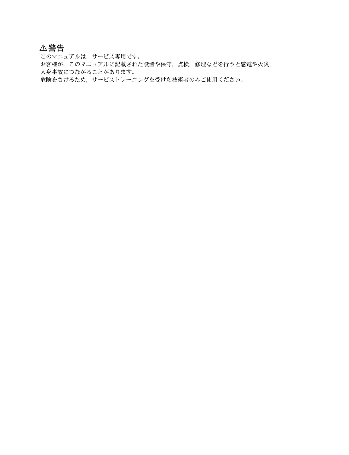
For customers in the U.S.A. and Canada
1Power cord, 125 V 10 A (2.4 m) : !1-557-377-11
AC inlet
1
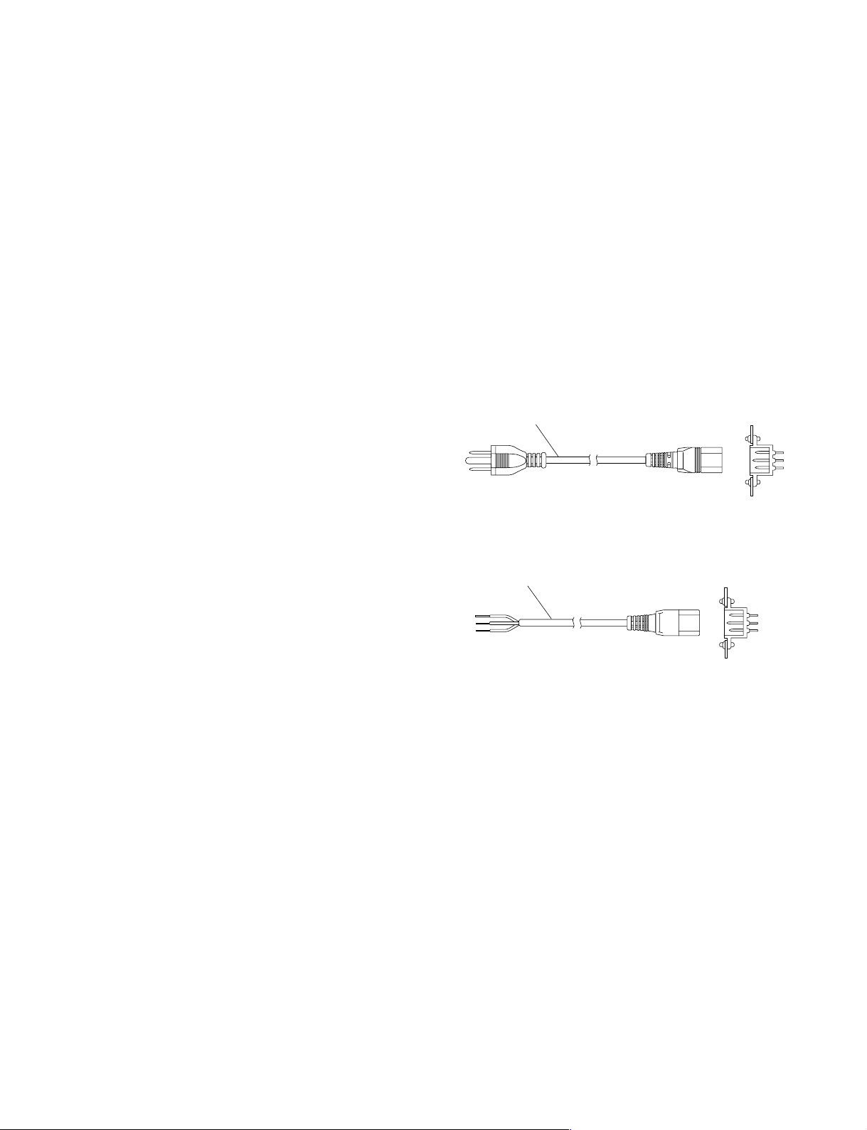
For customers in the all Europian countories
1Power cord, 250 V 10 A (2.4 m) : !1-782-929-21
1
AC inlet
1-1. Operating Environment
Operating guaranteed temperature : +5 dC to +40 dC
Performance guaranteed temperature : +10 dC to +35 dC
Operating humidity : 10 % to 90 %
Storage temperature : _20 dC to +60 dC
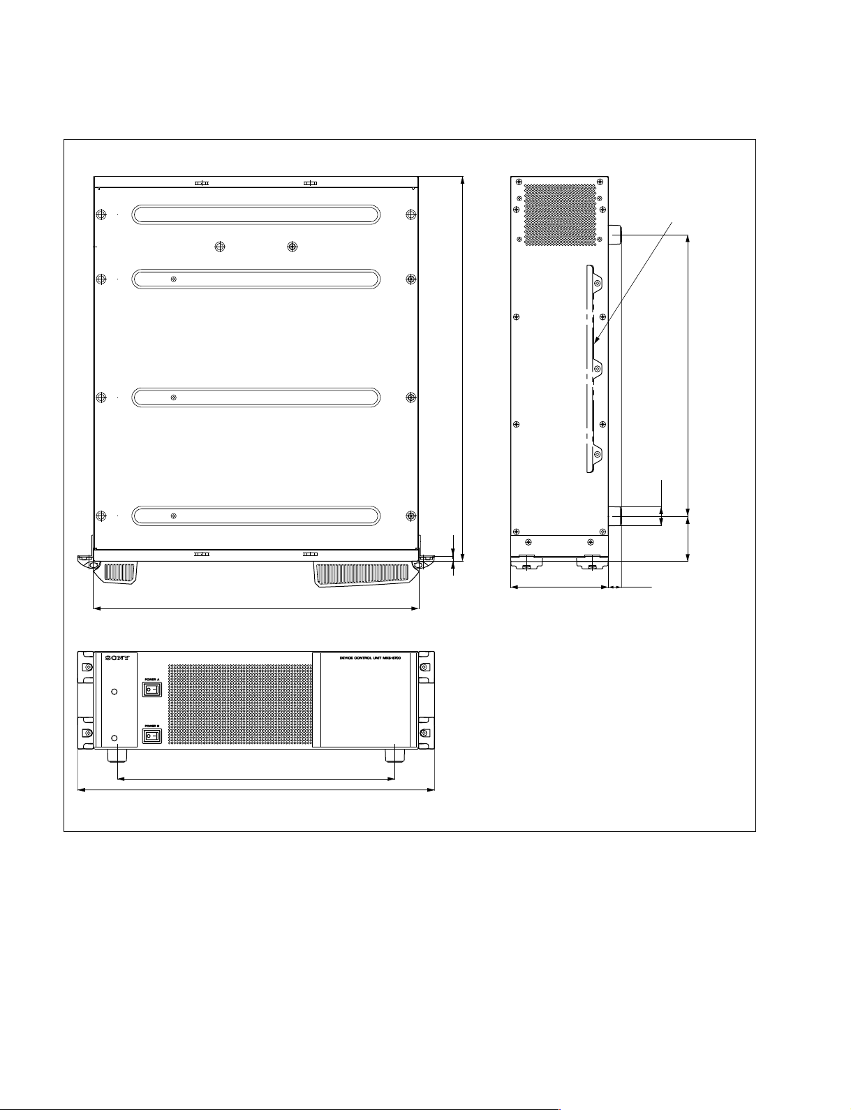
Mass : Approx. 18 kg
(with all options
installed)
Prohibited locations for installation
.Areas where the unit will be exposed do direct sunlight
or any other strong lights.
.Dusty areas
.Areas is subject to vibration.
.Areas with strong electric or magnetic fields.
.Areas near heat sources.
.Areas subject to electrical noise.
.Areas subject to static electricity.
Ventilation
The inside of the DCU-8000 is cooled by a fan (both sides
on the rear).
The power supply can be damaged if the exhaust vent
(both sides on the rear) and air intake (front panel) are
blocked or the fan is stopped.
Therefore, leave a blank space of more than 10 cm in the
front and back of the DCU-8000.
1-2. Power Supply
1-2-1. Power Specifications
A switching regulator is used for the power supply of this
unit. A voltage within the range of 100 V to 240 V can be
used without changing the supply voltage.
Power requirements : AC 100 to 240 V ±10 %
Power frequency : 50/60 Hz
Current consumption : Maximum 1.4 A
n
As the inrush current at turn-on is a maximum 20 A (at 100
V)/60 A (at 230 V), the capacity of the AC power must be
commensurate with this source load.
If the capacity of the AC power is not adequately large, the
AC power source breaker will operate or the unit will
abnormally operate.

1-2 DCU-8000 IM
7520
440
482
375
17.5
380
61
ø26
132.4
Rack mount metal
(supplied with RMM-10)
Unit : mm
1-3. Installation Space (External dimensions)

1-3
DCU-8000 IM
1-4. Installing the Options
The DCU-8000 is shipped from the factory with the necessary options (refer to the following table)
already installed in the MKS-8700, in accordance with the specified system configuration.
DCU-8000 Options
Model name Structure
Plug-in board Connector board
MKS-8701 Tally/GPI Output Board RC-90 board CN-2195 board
MKS-8702 Serial Interface Board IF-848 board CN-2194 board
HK-PSU03 Backup Power Supply Unit _
1-4. Installing the Options

1-4 DCU-8000 IM
Screws
(with drop-safe)
Screws
(with drop-safe)
1-4. Installing the Options
1-4-1. Installing the Plug-in Boards
n
Be sure to turn off the POWER switch before starting
installation work.
If installation work is started with the POWER switch left
on, it may cause electrical shock or damage to printed
circuit boards.
Installation
1. Turn off the main power of the MKS-8700 and
disconnect the AC power cord from the wall outlet.
2. Loosen the four screws (with drop-safe) and remove
the front panel in the direction of the arrow.
3. Remove the four screws (B3 x5) and remove the
plug-in board loose-proof assembly.
4. While the eject levers are kept open as shown in the
illustration, insert the plug-in board into the board
guide rails.
Name of option Name of board
Slot on the front side
MKS-8701 RC-90 2, 3, 4, 5, 6
MKS-8702 IF-848 2, 3, 4, 5, 6
B3 x 5
B3 x 5
Plug-in board
loose-proof assembly
Eject levers
Plug-in board

1-5
DCU-8000 IM
5. While closing the eject levers in the direction of arrow
1, push in the plug-in board.
6. Attach the plug-in board loose-proof assembly and the
front panel by reversing the installation steps of 2, 3.
1-4. Installing the Options
11
Eject levers
Plug-in board
1-4-2. Installing the Connector Board
Installation
1. Remove the screw or the two installing screws from
the slot into which the connector board is going to be
installed. Then remove the blank panel or the
connector board.
n
Store the removed blank panel in a safe place.
2. Insert the connector board horizontally level and
secure it with the two fixing screws.
Name of option Name of board Slot on the rear side
MKS-8701 CN-2195 Install the board into the
slot in the rear that
corresponds to the RC-90
board that is inserted in
the slot in the front.
MKS-8702 CN-2194 Install the board into the
slot in the rear that
corresponds to the IF-848
board that is inserted in
the slot in the front.
B3 x 5
Blank panel
Connector board
Fixing screw
Fixing screw

1-6 DCU-8000 IM
1-4-3. Installing the HK-PSU03
The HK-PSU03 is used after it is installed in the MKS-
8700.
n
Be sure to turn off the POWER switch before starting
installation work.
If installation work is started with the POWER switch left
on, it may cause electrical shock or damage to printed
circuit boards.
Installation
1. Remove the front panel. (Refer to Section 1-4-1)
2. Loosen the two screws fixing the blank panel of the
slot to which you want to install the HK-PSU03.
Remove the blank panel.
n
Store the removed blank panel in a safe location.
3. Install the HK-PSU03 firmly as far as it will go.
4. Secure the HK-PSU03 with the two screws.
1-4. Installing the Options
B3 x 5
Blank panel
B3 x 5
HK-PSU03

1-7
DCU-8000 IM
1-5. Rack Mounting
The DCU-8000 installs in a 19-inch standard rack.
To mount the DCU-8000 in a rack, use the specified rack
mount kit and follow the procedure described below.
Specified rack mount kit : RMM-10
n
If a rack mount kit other than the specified one is used, the
unit may not correctly install in 19-inch standard rack.
Parts of the RMM-10
.Rack tools 2 pcs
.Right rack mount adaptor 1 pc
.Left rack mount adaptor 1 pc
.Rack tool attaching screws 6 pcs
(B4 x6 : 7-682-560-09)
.Rack tool attaching screws 6 pcs
(B4 x10 : 7-682-560-10)
1. Precautions for rack mounting
w
.To prevent the rack from falling or moving, fix the rack
on a flat and steady floor using bolts or others fixings.
If the rack falls due to the weight of the equipment, it
may cause death or injury.
.Be sure to use the specified rack mount kit.
If not, injury may result and the equipment may fall due
to insufficient strength.
.After rack mounting, be sure to tighten the screws on the
rack angle and fix the unit in the rack.
If the screws on the rack angle are not tightened, the unit
may slip from the rack and fall, causing injury.
c
When mounting the unit in the rack, note the following:
.Be sure to mount in the rack with two persons or more.
.Be careful not to catch your fingers or hands in the rack
mount rail or others.
.Mount in the rack in a stable position.
n
If several units are mounted in a rack, it is recommended
that a ventilation fan is installed to prevent temperature rise
inside the rack.
2. Rack mounting procedure
This section describes the rack mounting procedure using
the RMM-10 rack mount kit.
n
Tighten the screws to the following torque.
Tightening torque : 120 x10_2N.m {12.2 kgf.cm}
1. Attach the rack tool to the side of the equipment using
the specified six screws.
n
Use B4 x6 screws.
2. Loosen the screws on the rear of the right and left
adaptors and adjust the length of the adaptor according
to the depth of the rack.
(The illustration below shows the left adaptor.)
n
Maximum depth of adaptor : 750 mm
Minimum depth of adaptor : 595 mm
B4 x 6
B4 x 6
Rack tools
Rack tools
B4 x6
Portion of
the rail
Adaptor
1-5. Rack Mounting

1-8 DCU-8000 IM
3. Attach the right and left adaptors to the rack complete-
ly using the specified six screws.
(The illustration below shows the left adaptor.)
4. Tighten the screws (B4 x6 : two screws each on the
right and left) for adjusting the length of the adaptor
completely (the screws that were loosened in step 2).
5. Align the groove of the rack tool at the side of the
equipment with the rail, and slide the equipment to the
rear.
n
The rack tools are hooked on the rails as shown below.
B4 x10
3U
B4 x10
31.75
31.75
Unit : mm
Rack tool Rack tool
Rail Rail
1-5. Rack Mounting
6. Remove the front panel. (Refer to Section 1-4-1)
7. Fix the rack angle in the rack using the specified
screws.
8. Attach the front panel to the equipment.
B5 x 12
B5 x 12
Rack
Rack angle
Rack angle

1-9
DCU-8000 IM
1-6. Matching Connectors and Cables
Use the following connectors, cables or equivalents when connecting cables to the unit.
Model name Panel indication Connector name Matching connector and cable
Name Sony part No.
MKS-8700 TALLY/GPI IN 1-34, D-sub 37-pin, Female D-sub 37-pin, Male
35-68, 69-102 Connector 37-pin, Male 1-566-357-11
Junction Shell 37-pin 1-563-378-11
SERIAL TALLY1, 2 D-sub 9-pin, Female D-sub 9-pin, Male
Connector 9-pin, Male 1-560-651-00*1
Junction Shell 9-pin 1-561-749-00
PERIPH RJ-45 modular jack*2__
REF IN BNC, 75 ZBNC, 75 Z_
Belden 8281 coaxial cable
MKS-8701 TALLY/GPI OUT 1-18, D-sub 37-pin, Female D-sub 37-pin, Male
19-36, 37-54 Connector 37-pin, Male 1-566-357-11
Junction Shell 37-pin 1-563-378-11
MKS-8702 REMOTE 1 to 6 D-sub 9-pin, Female D-sub 9-pin, Male
Connector 9-pin, Male 1-560-651-00*1
Junction Shell 9-pin 1-561-749-00
*1 : The following crimp contact is required for the plug.
AWG#18 to #22 : 1-566-493-21
AWG#22 to #24 : 1-564-774-11
AWG#24 to #30 : 1-564-775-11
*2 : Conforms to the IEEE 802.3 Ethernet 100BASE-TX standards.

1-10 DCU-8000 IM
_ EXT VIEW _
1
5
69
18
_ EXT VIEW _
1-7. Input/Output Signals of Connectors
The input/output signals of the connectors at the rear panel
are as follows.
n
<CONTROLLER> indicates a controlling device.
<DEVICE> indicates a controlled device.
1-7-1. MKS-8700
SERIAL TALLY 1, 2 : RS-422A (D-sub 9-pin, Female)
<CONTROLLER> to Tally Interface Unit (*1)
Pin No. Signal Name Function
1 FG Frame ground
2RX_Received data (_)
3TX+Transmitted data (+)
4 GND Common ground
5_No Connection
6 GND Common ground
7RX+Received data (+)
8TX_Transmitted data (_)
9_No Connection
(*1) :
TALLY INTERFACE UNIT BKDS-6080 and others.
PERIPH :
100BASE-TX, RJ-45 (8-pin)
Pin No. Signal Name Function
1TX+Transmitted data (+)
2TX_Transmitted data (_)
3RX+Received data (+)
4_No Connection
5_No Connection
6RX_Received data (_)
7_No Connection
8_No Connection
119
2037
TALLY/GPI IN 1-34 : D-sub 37-pin, Female
INPUT x34, TTL, 2 INPUT TTL/+12 V Switchable (*2)
_EXT VIEW_
Pin No. Signal Name Function
1 TALLY/GPI IN 1 Tally/GPI inputs
2 TALLY/GPI IN 3
3 TALLY/GPI IN 5
4 TALLY/GPI IN 7
5 TALLY/GPI IN 9
6 TALLY/GPI IN 11
7 TALLY/GPI IN 13
8 TALLY/GPI IN 15
9 TALLY/GPI IN 17
10 TALLY/GPI IN 19
11 TALLY/GPI IN 21
12 TALLY/GPI IN 23
13 TALLY/GPI IN 25
14 TALLY/GPI IN 27
15 TALLY/GPI IN 29
16 TALLY/GPI IN 31
17 TALLY/GPI IN 33 (*2)
18 GND Ground
19 GND Ground
20 TALLY/GPI IN 2 Tally/GPI inputs
21 TALLY/GPI IN 4
22 TALLY/GPI IN 6
23 TALLY/GPI IN 8
24 TALLY/GPI IN 10
25 TALLY/GPI IN 12
26 TALLY/GPI IN 14
27 TALLY/GPI IN 16
28 TALLY/GPI IN 18
29 TALLY/GPI IN 20
30 TALLY/GPI IN 22
31 TALLY/GPI IN 24
32 TALLY/GPI IN 26
33 TALLY/GPI IN 28
34 TALLY/GPI IN 30
35 TALLY/GPI IN 32
36 TALLY/GPI IN 34 (*2)
37 GND Ground

1-11
DCU-8000 IM
119
2037
TALLY/GPI IN 69-102 : D-sub 37-pin, Female
INPUT x34, TTL, 2 INPUT TTL/+12 V Switchable (*2)
_EXT VIEW_
Pin No. Signal Name Function
1 TALLY/GPI IN 69 Tally/GPI inputs
2 TALLY/GPI IN 71
3 TALLY/GPI IN 73
4 TALLY/GPI IN 75
5 TALLY/GPI IN 77
6 TALLY/GPI IN 79
7 TALLY/GPI IN 81
8 TALLY/GPI IN 83
9 TALLY/GPI IN 85
10 TALLY/GPI IN 87
11 TALLY/GPI IN 89
12 TALLY/GPI IN 91
13 TALLY/GPI IN 93
14 TALLY/GPI IN 95
15 TALLY/GPI IN 97
16 TALLY/GPI IN 99
17 TALLY/GPI IN 101 (*2)
18 GND Ground
19 GND Ground
20 TALLY/GPI IN 70 Tally/GPI inputs
21 TALLY/GPI IN 72
22 TALLY/GPI IN 74
23 TALLY/GPI IN 76
24 TALLY/GPI IN 78
25 TALLY/GPI IN 80
26 TALLY/GPI IN 82
27 TALLY/GPI IN 84
28 TALLY/GPI IN 86
29 TALLY/GPI IN 88
30 TALLY/GPI IN 90
31 TALLY/GPI IN 92
32 TALLY/GPI IN 94
33 TALLY/GPI IN 96
34 TALLY/GPI IN 98
35 TALLY/GPI IN 100
36 TALLY/GPI IN 102 (*2)
37 GND Ground
119
2037
1-7. Input/Output Signals of Connectors
TALLY/GPI IN 35-68 : D-sub 37-pin, Female
INPUT x34, TTL, 2 INPUT TTL/+12 V Switchable (*2)
_EXT VIEW_
Pin No. Signal Name Function
1 TALLY/GPI IN 35 Tally/GPI inputs
2 TALLY/GPI IN 37
3 TALLY/GPI IN 39
4 TALLY/GPI IN 41
5 TALLY/GPI IN 43
6 TALLY/GPI IN 45
7 TALLY/GPI IN 47
8 TALLY/GPI IN 49
9 TALLY/GPI IN 51
10 TALLY/GPI IN 53
11 TALLY/GPI IN 55
12 TALLY/GPI IN 57
13 TALLY/GPI IN 59
14 TALLY/GPI IN 61
15 TALLY/GPI IN 63
16 TALLY/GPI IN 65
17 TALLY/GPI IN 67 (*2)
18 GND Ground
19 GND Ground
20 TALLY/GPI IN 36 Tally/GPI inputs
21 TALLY/GPI IN 38
22 TALLY/GPI IN 40
23 TALLY/GPI IN 42
24 TALLY/GPI IN 44
25 TALLY/GPI IN 46
26 TALLY/GPI IN 48
27 TALLY/GPI IN 50
28 TALLY/GPI IN 52
29 TALLY/GPI IN 54
30 TALLY/GPI IN 56
31 TALLY/GPI IN 58
32 TALLY/GPI IN 60
33 TALLY/GPI IN 62
34 TALLY/GPI IN 64
35 TALLY/GPI IN 66
36 TALLY/GPI IN 68 (*2)
37 GND Ground

1-12 DCU-8000 IM
119
2037
<Relay>
TALLY/GPI OUT xB
TALLY/GPI OUT xA
1-7. Input/Output Signals of Connectors
1-7-2. MKS-8701
TALLY/GPI OUT 1-18 : D-sub 37-pin, Female
OUTPUT x18, relay contacts 30 V 0.1 A (*3)
_EXT VIEW_
Pin No. Signal Name Function
1 TALLY/GPI OUT 1A Tally/GPI outputs
2 TALLY/GPI OUT 2A
3 TALLY/GPI OUT 3A
4 TALLY/GPI OUT 4A
5 TALLY/GPI OUT 5A
6 TALLY/GPI OUT 6A
7 TALLY/GPI OUT 7A
8 TALLY/GPI OUT 8A
9 TALLY/GPI OUT 9A
10 TALLY/GPI OUT 10A
11 TALLY/GPI OUT 11A
12 TALLY/GPI OUT 12A
13 TALLY/GPI OUT 13A
14 TALLY/GPI OUT 14A
15 TALLY/GPI OUT 15A
16 TALLY/GPI OUT 16A
17 TALLY/GPI OUT 17A
18 TALLY/GPI OUT 18A
19 GND Ground
20 TALLY/GPI OUT 1B Tally/GPI outputs
21 TALLY/GPI OUT 2B
22 TALLY/GPI OUT 3B
23 TALLY/GPI OUT 4B
24 TALLY/GPI OUT 5B
25 TALLY/GPI OUT 6B
26 TALLY/GPI OUT 7B
27 TALLY/GPI OUT 8B
28 TALLY/GPI OUT 9B
29 TALLY/GPI OUT 10B
Pin No. Signal Name Function
30 TALLY/GPI OUT 11B Tally/GPI outputs
31 TALLY/GPI OUT 12B
32 TALLY/GPI OUT 13B
33 TALLY/GPI OUT 14B
34 TALLY/GPI OUT 15B
35 TALLY/GPI OUT 16B
36 TALLY/GPI OUT 17B
37 TALLY/GPI OUT 18B
(*3)
n
A and B of the same number constitute a pair of relay
contacts.
Other manuals for DCU-8000
1
This manual suits for next models
4
Table of contents
Other Sony Switch manuals

Sony
Sony BRS-200 Quick start guide

Sony
Sony HDS-7150 User manual

Sony
Sony XVS-G1 User manual

Sony
Sony DMX-SW1 - Bravia Input Link User manual

Sony
Sony XVS-G1 User manual

Sony
Sony CCP-8000 Series User manual

Sony
Sony BVS-3200CP User manual

Sony
Sony DVS-9000 User manual

Sony
Sony DVS-V3232M User manual

Sony
Sony MVS-3000A User guide

Sony
Sony HDS-7100 User manual

Sony
Sony MVS -8000X User manual

Sony
Sony MVS-8000G-C Quick start guide

Sony
Sony DFS-500 User manual

Sony
Sony DFS-900M User manual

Sony
Sony BRS-200 User manual

Sony
Sony MVS-6000-C User manual

Sony
Sony DVS-7200A User manual

Sony
Sony MVS-8000X System User manual

Sony
Sony MCS-8M User manual