WF-\0)(-Me)m@relai(-
alt
Before
using
the
DAT
deck
WEIN)
2s:
ncn
sicaiornenn
oeeiea
ican
acnannianeabiade
Digital
audio
tape
..
Precautions
Feature
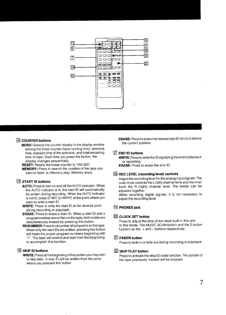
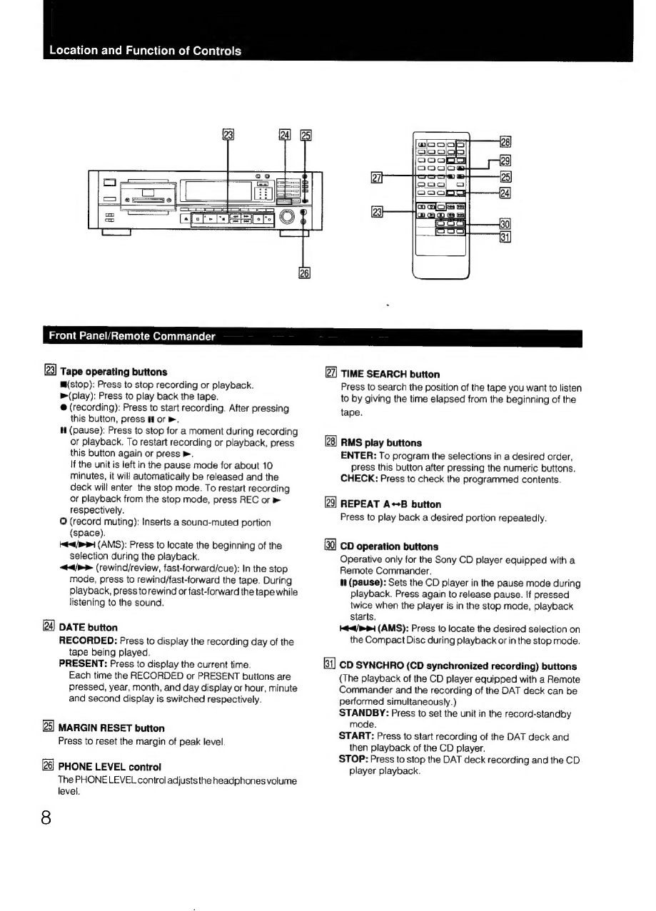
Location
and
function
of
controls
Front
panel/remote
commander
..
Remote
commander
operation
Installing
batteries
....
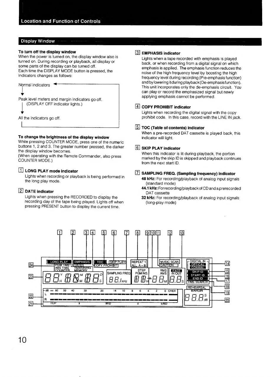
Display
window
..
Connections
Rear
panel
jacks
Connection
examples
..
Time
setting
Setting
the
date
and
time...
Cassette
loading
Recording
Before
recording
Blank
section
and
sound-muted
portion...
Absolute
time
codes
Recording
To
record
the
recording
date
and
time
.....
To
monitor
the
recording
condition
.........
To
check
the
recording
date
and
time
.
Creating
a
sound
muted
portion
BAG
SGSCCM
i
cidanneccsaced
civsivaess
:
Fade-in/fade-out
recording...
CD
synchronized
recording
....
Writing
sub
codes
BUY
COMES
as.
dunner
atoaanrnuanty
suncalveesdamedecieastidleeg
rie
tieness
24
Siar
sec
haanaeds
ol
uc
vanyinia
onan
aaevausan
nature
aanenniaeals
:
Writing
automatically
during
recording
Writing
manually
during
recording
...........
;
Writing
manually
during
playback
..
Adjusting
the
position
....
EPASinQ
vessvsiienceceerees
‘
PPOGrAMNUMBEIS:,
cc:scscetisdarcodesed
te
tenpasseansieanaaatedvettess
Writing
automatically
during
recording
........0..:ce
28
Renumbering
Erasing
Skip
ID
Writing
during
recording...
Writing
during
playback
Writing
during
recording...
Writing
during
playback
..
Erasing
Playback
Playback
Display
window...
ot
Auto
play:
restarting
playback
after
rewinding............
34
Time
search:
fast-forwarding/rewinding
the
tape
by
designating
the
amount
in
minutes
..0....
ee
34
Time
search:
To
start
playback
by
designating
the
elapsed
time
form
the
beginning
of
a
tape
.
Various
playback
operations
Fade-in/fade-out
play
Repeat
play
Automatic
music
sensor
operation
....
Music
scan
Designating
the
desired
selection
..
Skip
play
Random
music
sensor
operation
Timer
activated
Operation...
cece
cee
teeteeeteeeeneenes
Timer
activated
recording
....
Timer
activated
playback
Maintenance
Cleaning
the
cabinet
...
Cleaning
the
head
Block
diagram
Technical
information
Recording
format
of
DAT
ats
Tape
format
and
construction
of
DAT
cassette
....
Track
format..........
Troubleshooting
Specifications
Digital
Audio
Tape
DAT
(Digital
Audio
Tape)
is
anew
recording
system
which
digitalizes
the
audio
signal
and
records
it
on
a
DAT
cassette
tape.
DAT
records
the
audio
signal
by
converting
the
analog
sound
into
a
digital
signal.
This
converting
system
is
called
the
PCM
(Pulse
Code
Modulation),
and
its
accurate
processing
of
the
audio
signal
allows
recording/playback
with
lower
wow
and
flutter,
wider
dynamic
range,
lower
distortion
rate,
and
superb
signal-to-noise
ratio.
In
addition,
various
control
codes
calls
sub
codes
can
be
written
on
the
DAT
cassette
separately
from
the
audio
signal.
They
are
written
for
a
variety
of
convenient
playback/tape
editing
operations,
and
except
for
the
absolute
time,
can
be
rewritten
after
audio
signal
recording
has
been
completed.