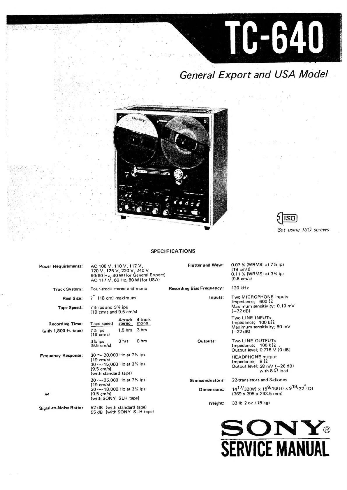
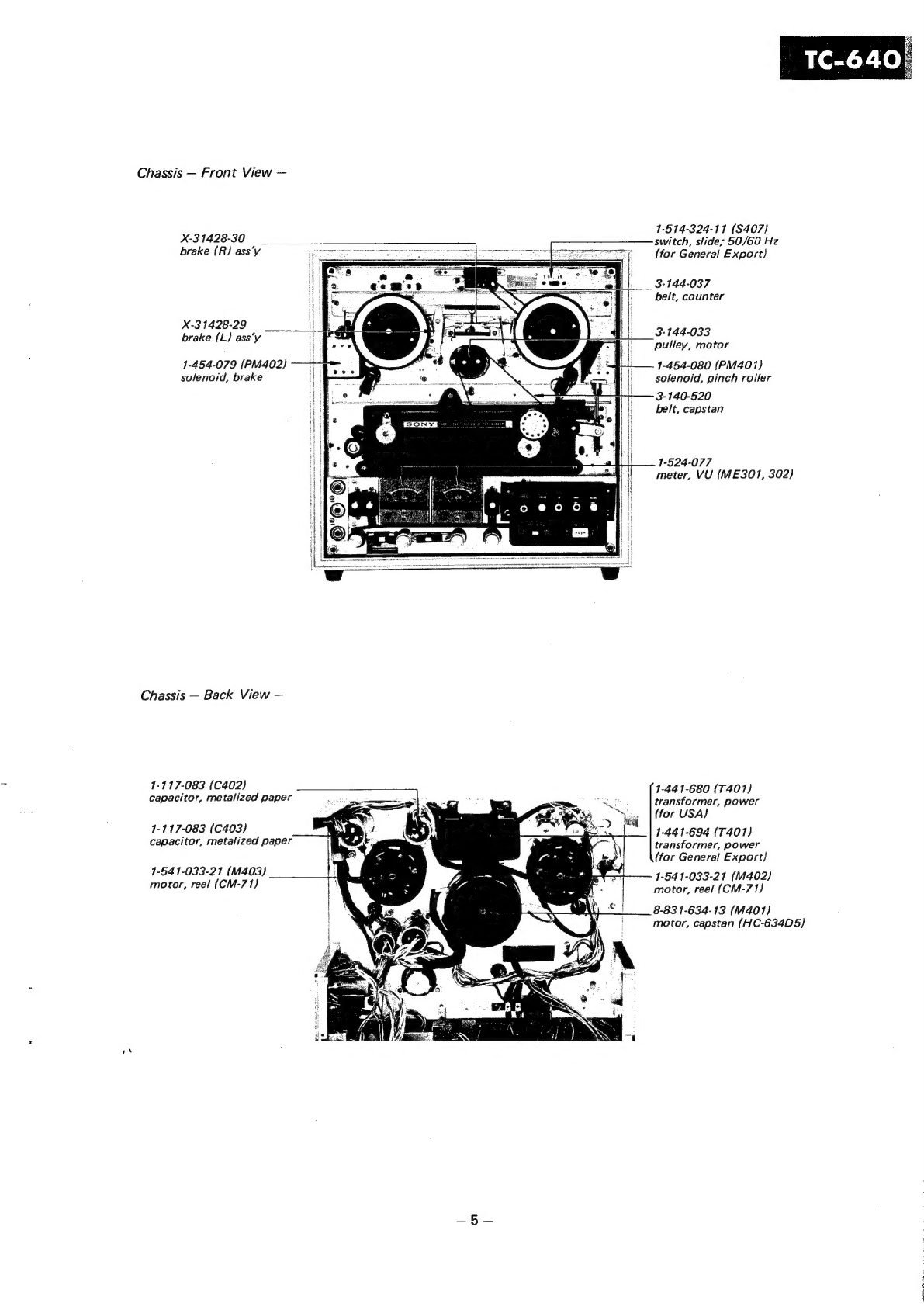
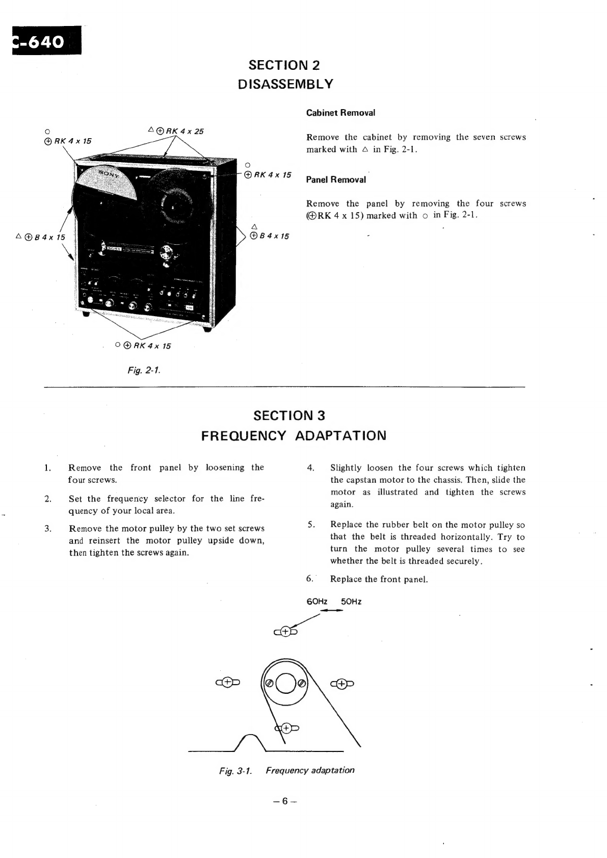
Sony TC-640 User manual

Power
Requirements:
Track
System:
Reel
Size:
Tape
Speed:
Recording
Time:
(with
1,800
ft.
tape)
Frequency
Response:
we
Signal-to-Noise
Ratio:
SPECIFICATIONS
AC
100
V,110V,117V,
120
V,
125
V,
220
V,
240
V
50/60
Hz,
80
W
(for
General
Export)
AC
117
V,
60
Hz,
80
W
(for
USA)
Four-track
stereo
and
mono
7”
(18
cm)
maximum
Inputs:
7%
ips
and
3%
ips
(19
cm/s
and
9.5
cm/s)
4-track 4-track
Tape
speed
stereo.
mono
7%
ips
1.5hrs
3hrs
(19
cm/s)
3%
ips
3hrs
6
hrs
Outputs:
(9.5
cm/s)
5
30
~
20,000
Hz
at
7%
ips
(19
cm/s)
30
~
15,000
Hz
at
3%
ips
(9.5
cm/s}
{with
standard
tape)
20
~
25,000
Hz
at
7%
ips
(19
cm/s)
30
~
18,000
Hz
at
3%
ips
(9.5
¢m/s)
(with
SONY
SLH
tape)
Weight:
52
dB
(with
standard
tape)
55
dB
(with
SONY
SLH
tape)
Flutter
and
Wow:
Recording
Bias
Frequency:
Semiconductors:
Dimensions:
8
[ISO)
Set
using
1SO
screws
0.07
%
(WRMS)
at
7%
ips
(19
cm/s)
0.11
%
(WRMS)
at
3%
ips
(9.5
cm/s)
120
kHz
Two
MICROPHONE
inputs
Impedance;
600
Maximum
sensitivity:
0.19
mV
(—72
dB)
Two
LINE
INPUTs
Impedance;
100
k{2
Maximum
sensitivity;
60
mV
(—22
dB)
Two
LINE
OUTPUTs
Impedance;
100kQ2
,
Output
level;
0.775
V
(0
dB)
HEADPHONE
output
Impedance;
8
Output
level;
38
mV
(—26
dB)
with
8
92
load
22-transistors
and
8-diodes
1417/32(w)
x
159/16(H)
x
919/32"
(D)
(369
x
395
x
243.5
mm)
33
Ib
2
0z
(15
kg)
SON
Ye
SERVICE
MANUAL

Section
Title
Specifications
1.
GENERAL
DESCRIPTION
1-1.
1-2.
Block
Diagram
Major
Parts
Locations
2.
DISASSEMBLY.............
3.
FREQUENCY
ADAPTATION
4.
MAINTENANCE
4-1.
Lubrication
..........
4-2.
Cleaning
eerie
bea
Bees
4-3.
Demagnetizing.........
5.
ADJUSTMENT
PROCEDURES
5-1,
5-2.
Mechanical
Adjustments.
...
Electrical
Adjustments.
...
6.
DIAGRAMS
6-1.
Schematic
Diagram
.....
6-2.
Mounting
Diagram
6-2-1.
REC
BIAS
Circuit
Board
.
.
6-2-2.
PB
AMP
Circuit
Board...
.
6-2-3.
System
Control
Circuit
Board
TABLE
OF
CONTENTS
Page
Section
Title
:
]
6-2-4.
REC
MODE
Circuit
Board
6-2-5.
SOS
&
ECHO
Circuit
Board
6-2-6.
Resistor
Terminal
......
3
6-3.
Level
Diagram.
.......
4~5
7.
SEMICONDUCTOR
ELECTRODES...
.
6
8.
ELECTRICAL
PARTS
LIST
....
:
6
9.
EXPLODED
VIEWS
9-1.
Cabinet
-
topview-—
....
7
9-2.
Amp
Chassis
:
7
—topview(l)-.....
‘
7
9-3.
Head
Deck
—top
view(1)
..
;
9-4.
Head
Deck
—top
view(2)
....
9-5.
Printed
Circuit
Board
—topview-—.......
8~11
9-6.
Chassis
—topview~.....
12~24
9-7.
Chassis
—bottom
view
~—.
. .
9-8.
Jack
Panel
.........
9-9,
Packing
20
5
Se
ee
5~28
é
10.
HARDWARES
............
29~32
Hardware
Nomenclature
.......
33~36
37~38

“AjuO
japoyy
Ju0dx
gy
jessuad
40}
papinosd
Ss}
(gOEP)
40;9aUUCD
gg/D3H
BULL
as
t
na
&}
9
‘GOES
MS
.JGOW
22H
“B
ae
i
el
tkL
‘OLLO
980
SVId
:210N
zoes
MS
YOLINOW
oO
FOHNOS
ce
No
©
FdVL
LfdLNO
INIT
AGE
SNA
a.
—-
©
[
IN
2
O
oO
a
waLaW
AA
60Z0
8020
L0z0
9020
|
8010
£010
9010
21w)
solo
—
Q
dNV
JNOHIGVFH
dWV
INIT
dWV
OF
ad
|
dW
037
934
dw
XIW
dW
JIN
O
Lu
x
”
oc
sos
£088
Lu
A
MS
a
{
oOHOF
8
SOS
Lu
VR-O
OHOI
re
yrs
40}28UU09
Gd/IFY
80er
JNOHdAV3H
{_
ZOES
9
22¥NOS
2068S
°
1vWHON
@-
4
cy
en
MS
193738
=
5
Pidaas
5
LNdLNo
ANIT
Ts
uOLINOM
AW
ANdNI
INIT
nee
a
wehbe
be
es
a
ayuVOS
LINDYID
7
[eal
dW
&d
cc
oO
<
a
x
°o
-
|
YRLIW
NIA
eee
£020
HY
2010
£010
nin
2)
010
a
dNV
3NOHdGV3H
dNV
INIT
|
dWy
07
934
dW
XIW
dV
JIN
=
-

1-2,
MAJOR
PARTS
LOCATIONS
Cabinet
—
Front
View
—
Y¥-20410-12-6S
counter,
tape
index
_
X-3
1440-08
3-144-042-10
cabinet
ass‘y,
wood
panel,
reel
3-140-864-01
3-140-864-01
reel
table
reel
table
1-514-692
switch,
lever;
MONITOR
(S302)
3-144-058
3-144-050-20
cover,
head
knob,
lever
switch;
REC
X-31408-07
x-
-3
1408-04
;
roller
ass’y,
guide
:
pinch
roller
ass’y
144-128
3-144-050-30
-
oe
tton
knob,
lever
switch;
rewind
1-514-769
(S305,
S306)
;
Spa
e
ee
er
3-144-050-40
knob,
lever
switch;
stop
3-144-050-10
knob,
lever
switch;
forward
3-144-050-30
knob,
lever
switch;
fast
forward
3-144-079
cover,
pushbutton
8B
1-514-789
switch,
slide;
TAPE
SPEED
(S301)
X-3
1440-09
knob
B
ass‘y,
PB
VOL
X-3
1440-09
knob
B
ass‘'y,
LINE
VOL
switch,
lever;
REC
MODE
1-507-28
1
(J301,
J302)
jack,
MICROPHONE
1-507-282
(J303)
jack,
binaural:
HEADPHONE
X-3
1440-11
knob
C
ass'y,
VOL
(ECHO/SOS)
1-514-324
(S303)
switch,
slide;
SOS
&
ECHO
X-31440-09
knob
B
ass'y,
MIC
VOL
1-513-347
switch,
slide;
TAPE
SELECT
(S307)
Cabinet
—
Back
View
—
3-456-002
grille,
ventilation
1-509-341
(CNJ402)
socket,
AC
OUTLET
171-509-064
1-507-142
(J304,
305)
socket,
voltage
jack,
phono:
LINE
INPUT
selector
(J403)
LINE
INPUT,
(for
General
Export}
171-509-029
(J308)
owen
SUPPLY
:
\
"
‘
connector,
REC/PB
171-509-062
(CNJ401)
seoune
4
!
~
:
(for
General
Export}
socket,
POWER
SUPPLY
®
5
\
i
:
f
1-507-142
(J306,
307}
jack,
phono;
LINE
OUTPUT
X-380
12-04
terminal
ass‘y,
GROUND
171-532-100
fuse,
2A

Chassis
—
Front
View
—
1-514-324-11
(S407)
switch,
slide;
50/60
Hz
(for
General
Export)
X-3
1428-30
brake
(R)
ass’y
3-144-037
be/t,
counter
X-3
1428-29
brake
(L}
ass‘y
3-144-033
pulley,
motor
1-454-080
(PM401)
solenoid,
pinch
roller
3-140-520
belt,
capstan
1-454-079
(PM402}
solenoid,
brake
1-524-077
meter,
VU
{(ME301,
302)
Chassis
—
Back
View
—
1-117-083
(C402)
capacitor,
metalized
paper
1-441-680
(T401)
transformer,
power
(for
USA)
1-441-694
(T401)
transformer,
power
(for
General
Export}
1-54
1-033-21
(M402)
motor,
reel
(CM-71)}
8-83
1-634-13
(M401)
motor,
capstan
(HC-634D5)
1-117-083
(C403)
capacitor,
metalized
paper
1-54
1-033-21
(M403)
motor,
reel
(CM-71)

SE
CTION
2
DISASSEMBLY
A@RK
4x25
O@RK
4x
15
Fig.
2-1.
Cabinet
Removal
Panel
SECTION
3
FREQUENCY
ADAPTATION
Remove
the
front
four
screws.
panel
by
loosening
the
Set
the
frequency
selector
for
the
line
fre-
quency
of
your
local
area.
Remove
the
motor
pulley
by
the
two
set
screws
and
reinsert
the
motor
pulley
upside
down,
then
tighten
the
screws
again.
cep
Remove
the
cabinet
by
removing
the
seven
screws
marked
with
A
in
Fig.
2-1.
Removal
Remove
the
panel
by
removing
the
four
screws
@RK
4
x
15)
marked
with
o
in
Fig.
2-1.
4.
Slightly
loosen
the
four
screws
which
tighten
the
capstan
motor
to
the
chassis.
Then,
slide
the
motor
as
illustrated
and
tighten
the
screws
again.
5.
Replace
the
rubber
belt
on
the
motor
pulley
so
that
the
belt
is
threaded
horizontally.
Try
to
turn
the
motor
pulley
several
times
to
see
whether
the
belt
is
threaded
securely.
6.
Replace
the
front
panel.
6OHz
50Hz
a
@(
je
cP
ee
Fig.
3-1.
Frequency
adaptation
es

SECTION
4
MAINTENANCE
4-1.
LUBRICATION
Use
light
machine
oil
and
lubricate
the
pinch
roller
shaft
and
capstan
drive
motor
lubricating
hole.
It
will
cause
slippage
of
the
mechanism.
If
the
oil
spills
on
the
pinch
roller
or
the
rubber
belt,
wipe
it
off
immediately
with
denatured
alcohol.
To
lubricate
them,
proceed
as
follows:
Avoid
excessive
lubrication.
(1)
Remove
the
head
cover
and
the
screw
securing
pinch
roller
and
then
lubricate
the
pinch
roller
shaft
with
one
drop
of
light
machine
oil.
(2)
Remove
the
reel
panel
and
lubricate
the
motor
lubricating
hole
with
several
drops
of
light
machine
oil.
Note:
Use
the
oil
which
is
comparatively
viscous
at
the
pinch
roller
shaft.
4-2.
CLEANING
Dusts
and
dirts
which
were
brought
by
tape
may
stick
to
the
core
of
the
record,
playback
or
erase
head,
and
they
may
deteriorate
the
perform-
ance
of
the
record
and
the
playback
heads.
So
wipe
off
the
surface
of
the
heads,
with
a
clean
and
soft
cloth
dampened
with
denatured
alcohol.
To
ensure
proper
operation,
the
heads
should
be
cleaned
at
least
once
during
each
ten
hours
of
actual
operation.
CAUTION
Do
not
use
any
other
‘solvent
on
the
head
as
some
will
damage
the
material
which
binds
the
head
laminations
together.
Also
do
not
use
any
metallic
device
which
will
scratch
the
head.
At
the
same
time,
clean
capstan,
rubber
belt,
pinch
roller,
tape
guide,
flutter
filter
roller
and
tension
arm.
4-3.
DEMAGNETIZING
The
record
and
playback
heads
may
occasionally
acquire
a
degree
of
permanent
magnetization,
which
will
result
in
an
increase
of
noise
level,
distortion
of
any
recorded
signal,
and
a
gradual
erasure
of
high
frequency
on
any
recorded
tape
which
passed
over
them.
These
heads
may
be
easily
demagnetized
with
a
SONY
head
demagnetizer
HE-2
(optional
accessory)
or
equivalent.
To
demagnetize
the
heads,
proceed
as
follows:
Steps:
(1)
Remove
the
head
cover.
(2)
Make
sure
that
power
switch
on
the
TC-640
is
in
the
OFF
position.
(3)
Connect
the
demagnetizer
to
ac
power
source.
(4)
Bring
the
tips
of
the
demagnetizer
in
close
proximity
to,
but
not
in
contact
with,
the
heads
so
that
the
tips
straddle
the
gap
in
the
center
of
the
head,
run
the
tips
up
and
down
the
heads
several
times,
and
then
slowly
with-
draw
the
demagnetizer.
CAUTION
Do
not
bring
magnet
close
to
heads.

5-1.
5-1-1.
SECTION
5
ADJUSTMENT
PROCEDURES
MECHANICAL
ADJUSTMENTS
171-117-083
(C402)
capacitor,
metalized
paper
171-117-083
(C403)
capacitor,
metalized
paper
1-541-033-21
(M403)
motor,
reel
(CM-71)
-
1-117-040
(C401)
capacitor,
metalized
paper
1-441-680
(T401)
transformer,
power
(for
USA)
1-441-694
(T4017)
transformer,
power
(for
General
Export)
1-541-033-21
(M402)
motor,
reel
(CM-71)
8-83
1-634-13
(M401)
motor,
capstan
(HC-634D5}
Adjusting
parts
locations
Automatic
Shut-off
Switch
Adjustment
Remove
the
head
deck
by
taking
off
the
two
screws,
and
put
it
upside
down
on
a
soft
cloth.
Make
sure
that
the
shut-off
lever
does
not
touch
the
head
deck
when
pushing
it
by
the
hand.
See
Fig.
5-1-1.
If
necessary,
adjust
the
position
of
the
actuator
bracket
by
loosening
the
screws
A.
Place
the
head
.
deck
See
Fig.
5-1-1.
in
a
normal
position.
Push
the
shut-off
lever
slowly
by
the
hand,
and
check
to
see
that
the
microswitch
turns
on
when
the
lever
comes
the
one-third
position
of
the
slot
as
shown
in
Fig.
5-1-2.
If
necessary,
adjust
the
position
of
the
micro-
switch
by
loosening
the
screws
(B)
and
(C).
Release
the
shut-off
lever,
and
make
sure
that
the
microswitch
turns
off
when
the
actuator
comes
at
one-fourth
position
of
the
slot
(See
Fig.
5-1-2).
Make
sure
that
the
shut-off
lever
reaches
the
top
of
the
slot
when
pushing
the
lever
by
the
hand.
9.
If
it
is
not,
readjust
the
position
of
the
actuator
bracket.
actuator
bracket
shut-off
lever
Fig.
5-1-1.
Automatic
shut-off
Switch
adjustment
(1)
shut-off
lever
ri
*]
one
_
U
%
ia
Fig.
5-1-2,
Automatic
shut-off
switch
adjustment
(2)

5-1-2.
Pinch
Roller
Pressure
Adjustment
1.
Place
the
unit
in
the
play
mode
to
energize
the
pinch
roller
solenoid,
and
turn
on
the
automatic
shut-off
switch.
Note:
Hold
the
shut-off
lever
so
that
the
shut-off
switch
is
activated
(a
rubber
band
or
a
piece
of
masking
tape
will
hold
the
shut-off
lever
as
though
tape
were
threaded
on
the
unit.)
2.
Adjust
the
adjusting
nut
(A)
for
1
mm
(3/64”
)
clearance
between
the
link
shaft
and
the
adjust-
ing
nut
(A).
See
Fig.
5-1-3.
:
3.
Attach
the
spring
scale
(5
kg)
to
the
pinch
roller
shaft
with
a
piece
of
string.
See
Fig.
5-1-4.
Pull
the
scale
horizontally
in
the
direction
shown
by
the
arrow.
The
capstan
shaft,
pinch
rolier
and
the
spring
scale
should
be
in
a
line.
Check
the
reading
just
when
the
pinch
roller
separates
from
the
capstan.
4,
Adjust
the
adjusting
nut
(B)
for
2.2
+
0.2
kg.
(4.4
to
5.3
1b)
5.
Repeat
steps
2
to
4
several
times.
6.
After
adjustment,
lock
the
adjusting
nut
(B)
by
the
lock
nut
(B).
7.
Adjust
the
adjusting
nut
(A)
for
the
clearance
of
0.1
to
0.2
mm
between
the
lock
nut
(A)
and
the
link
shaft.
8,
Lock
the
adjusting
nut
(A)
by
the
lock
nut
(A).
9,
Check
for
the
correct
value
again.
link
shaft
areal
lock
nut
(A)
adjusting
nut
(B)
adjusting
nut
(A)
Fig.
5-1-3.
Pinch
roller
pressure
adjustment
(1)
Pull
the
spring
scale
aA
in
the
direction
shown
by
the
arrow.
capstan
TS
pinch
roller
Fig.
5-1-4.
Pinch
roller
pressure
adjustment
(2)
5-1-3.
Microswitch
Position
Adjustment
1.
Check
to
see
that
the
microswitch
(for
pinch
roller
solenoid)
is
turned
on
when
the
pinch
roller
touches
the
capstan.
See
Fig.
5-1-5.
2. If
it
is
not,
adjust
the
position
of
the
micro-
switch
by
loosening
the
screws
A.
to
be
contact
capstan
pinch
roller
Fig.
5-1-5.
Microswitch
position
adjustment
5-1-4.
Reel
Motor
Torque
Adjustment
Take-up
Motor
Torque
Adjustment
1.
Place
the
reel
with
string
wound
several
turns
clockwise
on
the
hub
(44
mm
dia)
onto
the
take-up
reel
table.
Tie
the
string
to
the
spring
scale.
2.
Hold
the
shut-off
lever
so
that
the
shut-off
switch
is
activated
(a
rubber
band
or
a
piece
of
masking
tape
will
hold
the
shut-off
lever
as
though
tape
were
threaded
on
the
unit).
3.
Place
the
unit
in
the
play
mode.
Pull
the
spring
scale
and
then
allow
to
take
up
the
string
on
the
reel
while
approaching
the
scale
to
the
reel
at
the
same
speed
of
tape
running.
Adjust
RV401
for
330
to
350
g-cm
(4.58
to
4.86
oz.
inch)
on
the
spring
scale.
See
Fig.
5-1-6.
Note:
Read
the
scale
while
moving
it.

5-1-5,
Back
Tension
Torque
Adjustment
Place
the
empty
hub
with
string
wound
several
turns
counterclockwise
on
the
hub
(44
mm
dia)
onto
the
supply
reel
table.
Tie
the
string
to
the
spring
scale.
Hold
the
shut-off
lever
so
that
the
shut-off
switch
is
activated
(a
rubber
band
or
a
piece
of
masking
tape
will
hold
the
shut-off
lever
as
though
tape
were
threaded
on
the
unit.)
Place
the
unit
in
the
play
mode.
Pull
the
spring
scale
at
the
same
speed
of
tape
running.
Adjust
RV402
for
240
to
260
g-cm
(3.32
to
3.60
oz.
inch)
on
the
spring
scale.
See
Fig.
5-1-6.
Note:
Read
the
scale
while
pulling
it.
Fig.
5-1-6.
Reel
motor
torque
adjustment
Brake
Torque
Adjustment
This
adjustment
should
be
performed
for
both
supply
and
take-up
sides.
Note:
The
instructions
in
[
)
are
applied
to
the
’
supply
brake
torque
adjustment.
Place
the
unit
in
the
STOP
mode.
Bend
the
portion
A
_
of
the
brake
lever
with
a
pair
of
pliers
so
that
the
clearance
between
the
brake
lever
and
the
limiter
is
approx.
2
mm
(5/64").
Place
an
empty
reel
with
string
wound
several
turns
counterclockwise
[clockwise]
on
the
hub
onto
the
reel
table.
Tie
the
spring
to
a
spring
scale.
—~10—
4.
Pull
the
spring
scale
horizontally
at
a
constant
speed,
making
sure
that
the
string
does
not
touch
either
flange
of
the
reel.
The
reel
table
will
rotate
counterclockwise
[
clockwise
}.
Take
a
reading
only
when
the
reel
table
is
in
steady
motion.
5.
Make
sure
that
the
brake
torque
is
350
to
450
g.cm
(4.86
to
6.25
oz.
inch).
6.
Place
an
empty
reel
with
string
wound
several
turns
clockwise
[counterclockwise]
on
the
hub
onto
the
reel
table.
Tie
the
spring
to
a
spring
scale.
ti
Pull
the
scale
horizontally
at
constant
speed,
making
sure
that
-the
string
does
not
touch
either
flange
of
the
reel.
The
reel
table
will
rotate
clockwise
{
counterclockwise
].
Take
a
reading
only
when
the
reel
table
is
in
steady
motion.
8.
Make
sure
that
the
brake
torque
is
1,000
to
1,300
g-cm
(13.9
to
18.1
oz.
inch).
9.
If
it
is
not,
change
the
hooking
position
of
the
spring
for
the
specified
brake
torque.
10.
Check
to
see
that
the
center
pole
of
the
solenoid
should
be
pulled
out
from
the
solenoid
by
approx.
3
mm(1/8")
in
STOP
mode
as
shown
in
Fig.
5-1-9.
If
it
is
not,
adjust
the
position
of
the
brake
arm
bracket
A
marked
with
x.
11.
Make
sure
that
the
capstan
belt
does
not
rub
against
the
portion
marked
with
a
of
the
brake
lever
in
the
play
mode.
Specification:
Brake
Torque
of
Supply
Reel
in
clockwise
turning
..
350
-
450
g-cm
(4.86
-
6.25
oz.
inch)
in
counterclockwise
turning
.
1,000
-
1,300
g-cm
(13.9
-
18.1
oz.
inch)
Brake
Torque
of
Take-up
Reel
1,000
-
1,300
g-cm
(13.9
-
18.1
oz.
inch)
in
clockwise
turning
..
in
counterclockwise
turning
..
350-450
g-cm
(4.86
-
6.25
oz.
inch)

brake
lever
5-1-6.
Reel
Table
Height
Adjustment
1.
Place
the
unit
in
the
play
mode.
2.
See
Fig.
5-1-11.
Adjust
the
height
of
the
take-
up
reel
table
by
loosening
the
set
screws
with
an
allen
wrench
so
that
the
tape
is
on
the
mid-
dle
portion
between
the
upper
and
lower
flanges
of
the
reel.
3.
Check
for
the
supply
reel
table
height
in
the
rewind
mode.
reel
table
a
allen
wrench
Fig.
5-1-10.
Reel
table
height
adjustment
(1)
yr
LIED
brake
arm
{A}
id
7
4
Upper
and
lower
clearance
should
be
equal
link
red
(B)
Fig.
5-1-9.
Brake
torque
adjustment
(3)
Fig.
5-1-11.
Reel
table
height
adjustment
(2)
oes
ee

5-2.
ELECTRICAL
ADJUSTMENTS
Before
making
adjustments,
carefully
read
the
followings.
:
1.
Clean
the
record,
playback
and
erase
heads
with
asoft
cloth
dampened
with
denatured
alcohol.
2
Demagnetize
the
record
and
playback
heads
with
a
head
demagnetizer
(SONY
HE-2
or
equivalent).
3.
Set
the
switches
to
the
following
positions,
unless
otherwise
indicated.
MONITOR
switch
.........
TAPE
TAPE
SELECT
switch
......
NORMAL
ECHO
&
SOS
VOL
switch
...
OFF
REC
MODE
switch.........
OFF
TAPE
SPEED
switch
.......
19
cm/s
4.
Input
Connection
audio
oscillator
REC
AMP
MIC
jack
Fig.
5-2-1.
5.
Output
Connection
VTVM
PB
AMP
MONITOR
jack
Fig.
5-2-2.
6.
Input
and
output
levels
are
specified
as
follows,
unless
otherwise
indicated.
Normal
input
level
MICROPHONE
LINE
INPUT
Input
signal
level
—60
dB
(0.775
mV)
—10
dB(0.245
V)
Signal
source
:
600
22
100
kQ
impedance
Normal
output
level
LINE
OUT
HEADPHONE
0
dB
(0.775
V)
—28
dB(31
mV)
Load
sesistor
100
kQ
8
Outputlevel
7.
Set
the
VOL
controls
to
the
following
position,
unless
otherwise
indicated.
(1)
MIC
VOL
(in
using
the
MIC
jack)
Set
the
LINE
VOL
controls
extremely
counterclockwise
and
the
MONITOR
switch
to
SOURCE.
Deliver
a
1
kHz
signal
(—60
dB)
to
the
MIC
jack
and
adjust
the
MIC
VOL
controls
so
that
the
LINE
OUT
level
is
0
dB
(0.775
V).
(2)
LINE
VOL
(In
using
the
LINE
INPUT
jack)
Set
the
MIC
VOL
controls
extremely
counter-
clockwise
and
the
MONITOR
switch
to
SOURCE.
Deliver
a
1
kHz
signal
(—10
dB)
to
the
LINE
INPUT
jack
and
adjust
the
LINE
VOL
controls
so
that
the
LINE
OUT
level
is
0
dB
(0.775
V).
(3)
PB
VOL
Set
the
MONITOR
switch
to
TAPE.
Play
the
Ist
tone
(400
Hz,
0
dB)
of
SONY
alignment
tape
and
adjust
the
PB
VOL
controls
so
that
the
LINE
OUT
level
is
0
dB
(0.775
V).
8.
The
adjustment
should
be
performed
for
both
L-CH
and
R-CH.
9.
The
test
equipments
required
for
the
adjustment
are
as
follows:
Audio
oscillator
Attenuator
Fixed
resistors
100
kQ2,
2.2
kQ
and
2.2
kQ
oscilloscope
VTVM
Standard
tape
(blank)
SONY
SLH
tape
(blank)
Non-metallic
screwdriver
SONY
alignment
tapes
J-19-F2,
J-9-F1,
distortion
meter
FAG
1
kHz
bandpass
filter
10.
A
blank
test
tape
should
be
a
new
tape
ora
well-demagnetized
tape.
11.
The
following
SONY
alignment
tapes
are
required
for
the
adjustments.
They
contain
the
following
information
in
the
sequence
indicated.
-
5
kHz]
400Hzj
400Hz|
5
kHz
3kHz)
160
Hz
80
Hz
-10
dB
OdB}
-10dB]
-10dB{
-10dB})
-10dB]
-10dB
J-19-F2
400
Hz|
400
Hz}
10
kHzji2.5
kHz
7kHz
80
Hz
40
Hz
OdB]
-10dB}
-!0dB]
-10dB/
-10dB]
-10
dB]
-10dB
J-19-A2
12.5
kHz
(-10
dB)

R213
19
cm/s
R214
9.5cmss
PB
EQ
adj
R254
9.5
cm/s
R253
19
cm/s
bias
adj
dummy
coil
adj
R232
R272
R115
R155
L101
1.
DC
Power
Voltage
Check
Specification:
21.5
+1Vdc
2.
Automatic
Shut-off
Switch
Operation
Check
3.
Function
Lever
Check
VU
adj
REC
GAIN
adj
REC
EQadj
Adjusting
parts
locations
system
control
circuit
board
voltmeter
1OKe)
DC
50
V
range
~13.—
Procedure
.
Turn
on
the
power
switch.
.
Check
for
the
reading
on
the
dc
voltmeter
connected
between
the
terminals
12
(+)
and
7
(—)
on
the
system
control
circuit
board.
.
Turn
on
the
power
switch.
.
Depress
the
play
lever
with
the
shut-off
lever
pushed
by
the
hand.
.
Make
sure
that
the
unit
is
set
in
the
play
mode.
.
Release
the
shut-off
lever.
The
play
lever
should
be
released
and
the
set
should
be
changed
to
the
stop
mode.
.
Turn
off
the
power
switch.
.
Thread
the
tape
along
the
tape
path.
.
Push
the
play
lever
(or
both
play
and
record
levers)
;
-
Turn
on
the
power
switch
with
ac
90
V
power
source.
.
Make
sure
that
the
tape
starts
to
run
in
the
play
(or
record)
mode.

4.
PB
Head
Test
Setup:
1.
Play
back
the
SONY
alignment
tape
(J-19-A2).
Azimuth
:
oscilloscope
|
2.
Adjust
the
adjusting
screws
for
maximum
playback
Adjustment
output
at
both
channels.
.
Make
sure
that
the
same
phase
is
obtained
at
2nd
tone
(400
Hz)
of
the
alignment
tape
(J-19-F
2).
.
When
touching
the
tape
near
the
playback
head
with
a
finger
or
a
nonmetallic
equipment,
make
sure
it
does
not
cause
a
higher
output
level.
REC
head
azimuth
adjusting
screws
PB
head
azimuth
adjusting
screws
same
phase
45° 90°
*
Screw
position:
Angle
where
the
maximum
output
level
is
obtained
Lissajous
figure
on
the
oscilloscope
*
Phase
difference
between
channels:
Same
phase
at
400
Hz
within
90
°
at
10
kHz
5.
VU
Meter
Test
Setup:
.
Place
the
unit
in
the
vertical
position.
Calibration
.
Make
sure
that
the
pointer
of
the
VU
meter
VTVM
indicates
—20
on
the
scale
with
no
input
signal
in
PB
AMP
the
play
mode.
100
k8t
Op
See
.
Play
back
the
first
tone
(400
Hz)
of
the
SONY
f
\
alignment
tape
(J-19-F2).
ever
PINE
OUT
[eck
.
Adjust
the
PB
VOL
control
to
obtain
0
dB
(0.775
V)
on
the
VTVM.
.
Adjust
R232
(R272)
to
obtain
0
VU
on
the
level
meter.
Notes:
1.
Gain
margin
of
PB
VOL
control
should
be
6
to
8
dB.
.
Do
not
turn
the
PB
VOL
control
after
the
above
step
4.
—14—

Test
Setup:
1.
Thread
a
blank
tape
along
the
tape
path.
6.
Azimuth
Adjustments
(Record
Head)
blank
tape
.
Deliver
a
10
kHz
signal
of
—80
dB
(77.5
UV)
to
the
MICROPHONE
jack.
AF
ose
REC
AMP
.
Set
the
MONITOR
switch
to
SOURCE.
MIC
jack
eee
tT
.
Adjust
the
azimuth
adjusting
screw
for
maximum
reading
on
the
VTVM.
-
Record
the
signal
on
the
blank
tape.
.
Make
sure
that
the
playback
output
is
not
increased
when
touching
the
tape
near
the
record
head
with
LINE
OUT
jack
a
finger
or
a
nonmetallic
rod.
Test
Setup:
.
Place
the
unit
in
the
record
mode.
.
Trap
Coil
palusement
_
Adjust
C191
(C192)
so
that
the
VI'VM
connected
ee
pai
REC
AMP
across
the
record
head
reads
approximately
10 V.
eakage
3.
Set
the
MIC
VOL
and
LINE
VOL
controls
extremely
counterclockwise.
Measurement
—>
REC
HEAD
check
100
kQQ
2
vTvM
Specification:
4.
Adjust
L195
and
L196
for
the
minimum
reading
on
the
VTVM
connected
to
the
check
points.
.
Measure
the
bias
current
leakage
in
the
playback
output
without
the
tape
threaded.
Notes:
*
Bias
current
1.
A
shielded
wire
should
not
be
used
for
the
lead
of
VT
VM.
leakage:
Less
than
—40
dB
.
Use
a
nonmetallic
screwdriver.
.
The
bias
current
leakage
measurement
is
requir-
ed
for
both
stereo
and
monaural
record
modes.
.
Check
points:
L-Ch
:
terminal
(2)
R-Ch
:
terminal
(42)
on
the
rec
bias
circuit
board
—~15—

Procedure
1.
Thread
a
blank
tape
along
the
tape
path.
Items
Remarks
8.
Record
Bias Test
Setup:
Adjustment
-
eae
pus
REG
AME
blank
tape
|
7
Set the
MIC
VOL
and
LINE
VOL
controls
to
the
specified
position
on
page
12.
_
J
.
Turn
the
trimmer
capacitorsC91
and
C92
clockwise
to
the
full
and
turn
them
counterclockwise
by
MIC
jack
ee
OTM
three
or
four
turns.
.
Deliver
a
1
kHz
signal
of
—60
dB
(0.775
mV)
to
the
MICROPHONE
jack.
.
Record
the
signal
on
the
blank
tape.
LINE
OUT
jack
6.
Turn
C91
(C92)
clockwise
slowly
until
the
VTVM
reads
a
maximum.
.
Turn
C91
(C92)
moreover
until
the
VWITVM
reads
0.5
dB
below
the
maximum
reading.
.
After
adjustment,
apply
lock
paint
to
the
capacitors.
—-
bias
current
9.
Record
Level
.
Thread
a
blank
tape
along
the
tape
path.
Adjustment
Test
Setup:
blank
tape
.
Set
the
MONITOR
switch
to
SOURCE.
Reo
REC
AMP
3.
Deliver
a
1
kHz
signal
of
—60
dB
(0.775
mV)
to
the
MICROPHONE
jack.
MIC
jack
-
--
4.
Adjust
the
MIC
VOL
control
to
obtain
0
dB
ee
(0.775
V)
on
the
VTVM.
Note:
When
changing
the
TAPE
SELECT
switch
to
SPECIAL,
make
sure
that
the
output
de-
creases
approximately
1
to
1.5
dB.
LINE
OUT
jack
.
Change
the
MONITOR
switch
to
TAPE.
.
Record
the
signal
on
the
blank
tape.
.
Adjust
R115
(R155)
to
obtain
0
dB
(0.775
V)
on
the
VTVM.
—
16
-—

10.
Playback
Test
Setup:
1.
Adjust
R213
(R253)
to
obtain
the
same
output
between
the
2nd
(400
Hz)
and
3rd
(10
kHz)
tones
VTVM
of
the
alignment
tape
(J-19-F
2).
Response
Measurement
PB_AMP
Oe
.
Play
the
alignment
tape
(J-19-F
2)
from
the
2nd
tone
19
cm/s
Ze
=
to
the
7th
tone.
(7-1/2
ips)
.
Measure
the
deviation
of
each
frequency
against
the
LINE
OUT
jack
2nd
tone.
Frequency
J-19-F2
.
Make
sure
that
the
satisfied
result
is
obtained.
Specification:
tape
level
deviation
tone
against
2nd
tone
oad
O+154B
(10
kHz)
an
0.+
1.5
dB
(12.5
kHz)
ou
0+1.5
dB
(7
kHz)
3
a
+
1.0
+
2.0
dB
(80
Hz)
Tth
+
1.0
+3.0dB
11.
Playback
Test
Setup:
.
Adjust
R214
(R254)
to
obtain
the
same
output
Frequency
between
the
3rd
(400
Hz)
and
4th
(5
kHz)
tones
of
Response
VTVM
the
alignment
tape
(J-9-F
1).
Measurement
.
9.5
cm/s
PB
AMP
.
Play
the
alignment
tape
(J-9-F1)
from
the
3rd
‘
f
T
100
kl
tone
to
the
7th
tone.
(3-3/4
ips)
sips
z
.
Measure
the
deviation
of
each
frequency
against
LINE
OUT
jack
the
3rd
tone.
J-9-F
1
<a
F ;
:
.
Make
sure
that
the
satisfied
result
is
obtained.
Specification:
tape
level
deviation
tone
against
3rd
tone
aa
0+1.5
dB
(5
kHz)
was
au
0+1.5
dB
(3
kHz)
oat
a
0+2dB
(160
Hz)
7
7th
(80
Hz)
Denar
247.5

Test
Setup:
i.
Set
the
TAPE
SPEED
switch
to
19
cm/s
(7-1/2
ips).
12.
Playback
Signal-to-
2.
Play
the
Ist
tone
(400
Hz)
of
the
SONY
alignment
tape
(J-19-F2).
VTVM
NS
LINE
OUT
jack
Noise
Ratio
.
Adjust
the
PB
VOL
control
so
that
the
VT
VM
will
indicate
0
dB
(0.775
V).
;
.
Place
the
unit
in
the
play
mode
without
any
tape.
J-19-F2
Note:
Hold
the
shut-off
lever
so
that
the
shut-off
switch
is
activated
(a
rubber
band
or
a
piece
of
Specification:
7/2
ips
(19
cm/s)
more
than
80:48
masking
tape
will
hold
the
shut-off
lever
as
though
tape
were
threaded
on
the
unit).
.
Note
the
VTVM
reading.
33/4
ips
(9.5
cm/s)
Seer
are
ree
more
than
48
dB
6.
Make
sure
that
the
difference
between
the
above
steps
2
and
4
is
more
than
50
dB.
.
Set
the
TAPE
SPEED
switch
to
9.5
cm/s
(3-3/4
ips).
.
Note
the
VI
VM
reading.
.
Make
sure
that
the
difference
between
the
above
steps
2
and
8
is
more
than
50
dB.
Test
Setup:
13.
Input
Level
Variation
F
REC
AMP
Check
a
Sled
6002
mic
O-faT
Fs
1
kHz
10
kX
=
rN
O
LINE
IN
ca
PB
AMP
LINE
AMP
Specification:
Level
variation
by
MIC
VOL
Control
*
MIC
VOL............
Less
than
0.5
dB
.
Set
the
LINE
VOL
control
to
the
normal
position.
2.
Deliver
a
1
kHz
signal
of
-10
dB
(0.245
V)
the
LINE
INPUT
jack.
*
LINE
VOL............
Less
than
0.5
dB
.
Check
for
the
level
variation
on
the
VTVM
by
turning
the
MIC
VOL
control
from
MIN
to
MAX.
Level
variation
by
LINE
VOL
Control
.
Set
the
MIC
VOL
control
to
the
normal
position.
.
Deliver
a
1
kHz
signal
of
—60
dB
(0.775
mV)
to
the
MIC
jack.
.
Check
forthe
level
variation
on
the
VTVM
by
turning
the
LINE
VOL
control
from
MIN
to
MAX.
—18—-—

14.
Minimum
Test
Setup:
Input
Level
REC
AMP
Check
ares
6002
MIC
©
ad
1
kHz
‘|19
kQU
LINE
IN
=
>
TAPE
ps
OUT
jack
{0}
O
Be]
PB
AMP
LINE
AMP
Specification:
.
Set
the
MONITOR
switch
to
SOURCE.
.
Deliver
a
1
kHz
signal
of
—72
dB
(0.2
mV)
to
the
MICROPHONE
jack.
MIC
jack
Less
than
—72
dB(0.2
mV)
.
Set
the
LINE
VOL
control
fully
counterclockwise.
LINE
INPUT
jack
Less
than
—22
dB(61
mV)
.
Make
sure
that
the
line
output
is
more
than
0
dB
on
the
VITVM
when
turning
the
MIC
VOL
control
fully
clockwise.
.
Deliver
a
1
kHz
signal
of
-22
dB
(61
mV)
to
the
LINE
INPUT
jack.
.
Set
the
MIC
VOL
control
fully
counterclockwise.
.
Make
sure
that
the
line
output
is
more
than
0
dB
on
the
VT'VM
when
turning
the
LINE
VOL
control
fully
clockwise.
Test
Setup:
.
Set
the
MIC
VOL
and
LINE
VOL
controls
to
the
normal
position.
.
Input
and
Output
Check
of
REC/PB
Connector
(This
check
is
applied
blank
tape
REC
AMP
eee
OS
2.
Connect
the
audio
oscillator
to
pin
1
(4)
and
2
of
the
REC/PB
connector.
3.
Deliver
a
1
kHz
signal
of
—34
dB
(15.5
mV)
from
the
audio
oscillator.
for
General
Export
model
.
Place
the
unit
in
the
record
mode.
only)
.
Make
sure
that
the
VIT'VM
reads
0
dB
(0.775
V).
6.
Disconnect
the
VTVM
from
the
LINE
OUT
jack
and
connect
it
to
pin
3
(5)
and
2
of
the
REC/PB
connector.
LINE
OUT
jack
Specification:
7.
Play
back
the
recorded
tape.
0+2dB
(0.62
—
0.97
V)
.
Make
sure
that
the
VTVM
reads
0
+
2
dB
(0.62
—
0.97
V).
—~19—

16.
Overall
Frequency
Test
Setup:
AF
osc
REC
AMP
_
Response
Adjustment
(NORMAL)
MIC
jack
Specification:
17.
Overall
Frequency
Test
Setup:
AP
ose
REC
AMP
Response
Adjustment
(SPECIAL)
Specification:
blank
tape
blank
tape
LINE
OUT
jack
speed
7-1/2ips
|
3-3/4
ips
(19
cm/s)
(9.5
cm/s)
—
20
—
.
Set
the
TAPE
.
Thread
a
blank
tape
along
the
tape
path.
.
Set
the
TAPE
SELECT
switch
to
NORMAL.
.
Set the
MIC
VOL
and
LINE
VOL
controls
to
the
specified
position
on
page
12.
.
Record
the
following
frequency
signals
of
—80
dB
(77.5
UV):
50
Hz,
100
Hz,
1
kHz,
5
kHz,
10
kHz,
1$
kHz
and
18
kHz
through
the
MICROPHONE
jack.
.
Make
sure
that
each
deviation
in
the
level
for
a
1
kHz
signal
is
within
the
specification.
.
If
it
is
not,
perform
the
record
bias
adjustment.
.
Thread
a
blank
tape
(SONY
SLH
tape)
along
the
tape
path.
SELECT
switch
to
SPECIAL.
.
Set
the
MIC
VOL
and
LINE
VOL
controls
to
the
specified
position
on
page
12.
.
Record
the
following
frequency
signals
of
—80
dB
(77.5
LV):
50
Hz,
100
Hz,
1
kHz,
5
kHz,
10
kHz,
15
kHz
and
18
kHz
through
the
MICROPHONE
jack.
.
Make
sure
that
each
deviation
in
the
level
for
a
1
kHz
signal
is
within
the
specification.
.
If
it is
not,
perform
the
record
bias
adjustment.
Table of contents
Other Sony Tape Deck manuals

Sony
Sony DTC-ZE700 User manual

Sony
Sony DTC-A8 User manual

Sony
Sony DTC-A6 User manual

Sony
Sony DTC-87ES User manual

Sony
Sony DTC-670 User manual

Sony
Sony PCM-R500 - Dat Recorder User manual

Sony
Sony DTC-300ES User manual

Sony
Sony GY-8240UWD User manual

Sony
Sony DTC-57ES User manual

Sony
Sony DTC-60ES User manual