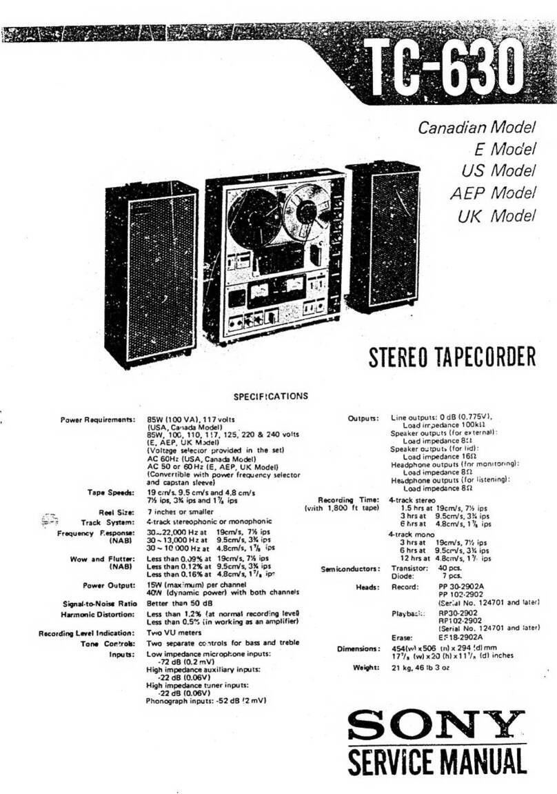
Sony GY-8240UWD User manual

DTF TAPE DRIVE
GY-8240UWD
GY-8240FC
MAINTENANCE MANUAL
1st Edition (Revised 5)
Serial No. 10001 and Higher

GY-8240UWD
GY-8240FC
!WARNING
This manual is intended for qualified service personnel only.
To reduce the risk of electric shock, fire or injury, do not perform any servicing other than that
contained in the operating instructions unless you are qualified to do so. Refer all servicing to
qualified service personnel.
!WARNUNG
Die Anleitung ist nur für qualifiziertes Fachpersonal bestimmt.
Alle Wartungsarbeiten dürfen nur von qualifiziertem Fachpersonal ausgeführt werden. Um die
Gefahr eines elektrischen Schlages, Feuergefahr und Verletzungen zu vermeiden, sind bei
Wartungsarbeiten strikt die Angaben in der Anleitung zu befolgen.Andere als die angegeben
Wartungsarbeiten dürfen nur von Personen ausgeführt werden, die eine spezielle Befähigung
dazu besitzen.
!AVERTISSEMENT
Ce manual est destiné uniquement aux personnes compétentes en charge de l’entretien. Afin
de réduire les risques de décharge électrique, d’incendie ou de blessure n’effectuer que les
réparations indiquées dans le mode d’emploi à moins d’être qualifié pour en effectuer d’autres.
Pour toute réparation faire appel à une personne compétente uniquement.
Attention-when the product is installed in Rack:
1. Prevention against overloading of branch circuit
When this product is installed in a rack and is
supplied power from an outlet on the rack, please
make sure that the rack does not overload the supply
circuit.
2. Providing protective earth
When this product is installed in a rack and is
supplied power from an outlet on the rack, please
confirm that the outlet is provided with a suitable
protective earth connection.
3. Internal air ambient temperature of the rack
When this product is installed in a rack, please make
sure that the internal air ambient temperature of the
rack is within the specified limit of this product.
4. Prevention against achieving hazardous
condition due to uneven mechanical loading
When this product is installed in a rack, please make
sure that the rack does not achieve hazardous
condition due to uneven mechanical loading.
For GY-8240FC:
Laser Diode Properties
Wave length : 850 nm
Laser output power: 0.398 mW (-4dBm) max.
CAUTION
Use of controls or adjustments or performance of
procedures other than those specified herein
may result in hazardous radiation exposure.
CLASS 1
LASER PRODUCT
LASER KLASSE 1
PRODUKT
This DTF Tape Drive is classified as a CLASS 1 LASER
PRODUCT. The CLASS 1 LASER PRODUCT label is
located on the rear panel.
Dieses DTF-Bandlaufwerk ist klassifiziert nach LASER
KLASSE 1 PRODUKT. Das LASER KLASSE 1
PRODUKT-Label befindet sich auf der Rückseite.

1
GY-8240UWD
GY-8240FC
Table of Contents
Manual Structure
Purpose of this manual .............................................................................................. 7
Relative manual ......................................................................................................... 7
Contents ..................................................................................................................... 7
Trademarks ................................................................................................................ 8
1. Service Overview
1-1. Removal/Installation of Cabinet .................................................................1-1
1-2. Cassette Compartment Removal/Installation ..............................................1-2
1-3. Main Parts Layout .......................................................................................1-4
1-3-1. Main Mechanical Parts Layout ..................................................1-4
1-3-2. Printed Circuit Boards Layouts ..................................................1-5
1-3-3. Function Descriptions and Sensors Layouts ..............................1-7
1-4. Internal Switch Setting ................................................................................1-9
1-5. Connector/Cable Information....................................................................1-10
1-6. Taking Out the Cassette in Tape Slacking ................................................1-14
1-7. Fixtures and Measuring Equipment for Adjustment .................................1-15
1-7-1. Fixtures.....................................................................................1-15
1-7-2. Measuring Equipment ..............................................................1-16
1-7-3. Alignment Tapes ......................................................................1-17
1-8. Power Block ..............................................................................................1-18
1-8-1. Switching Regulator Replacement ...........................................1-18
1-8-2. Fan Motor (Power Supply) Replacement.................................1-19
1-8-3. Voltage and Power Requirements ............................................1-19
1-8-4. Power Cord...............................................................................1-20
1-9. Replacement of the Boards .......................................................................1-21
1-9-1. Index.........................................................................................1-21
1-9-2. DPR-160 and FM-75 Boards Replacement..............................1-22
1-9-3. IF-780 and SCS-28, FC-82 Boards Replacement ....................1-22
1-9-4. CCM-33 Board Replacement ...................................................1-23
1-9-5. DSP-90 Board Replacement ....................................................1-23
1-9-6. CT-205 Board Replacement.....................................................1-24
1-9-7. HN-258 Board Replacement ....................................................1-24
1-9-8. SV-205 Board Replacement.....................................................1-25
1-10. Functions of LED Indicators on Circuit Boards .......................................1-27
1-11. Line Mode .................................................................................................1-28
1-11-1. Overview ..................................................................................1-28
1-11-2. Starting/Ending the Line Mode ................................................1-29
1-11-3. Switch Function .......................................................................1-30
1-11-4. Setting Mode ............................................................................1-31

2GY-8240UWD
GY-8240FC
1-12. SCSI Control Software scsitool.exe ..........................................................1-33
1-12-1. Operating Environment ............................................................1-33
1-12-2. Connection ...............................................................................1-33
1-12-3. Starting .....................................................................................1-34
1-12-4. Ending ......................................................................................1-34
1-12-5. Functions ..................................................................................1-35
1-12-6. SCSITOOL-AGING Command ...............................................1-47
1-13. General Function Check Using the SCSI Control Function .....................1-53
1-14. Revision Label ..........................................................................................1-57
1-14-1. Revision Label for Firmware/Hardware ..................................1-57
1-14-2. Revision Label for Board .........................................................1-58
1-15. Update of the Firmware ............................................................................1-59
1-15-1. Update with the Serial Port ......................................................1-59
1-15-2. Update with DTF-2 Cassette ....................................................1-61
1-15-3. Update with the Network (ftp) .................................................1-62
1-15-4. Update using PSC ....................................................................1-63
1-16. General Information of Device Connection ..............................................1-65
2. Periodic Maintenance and Inspection
2-1. Periodic Check ............................................................................................2-1
2-1-1. Hours Meter ...............................................................................2-1
2-1-2. Periodic Check List ....................................................................2-2
2-2. Cleaning ......................................................................................................2-4
2-2-1. General Information for Cleaning ..............................................2-4
2-2-2. Tape Running Surface of Upper Drum and
Rotary Heads Cleaning ..............................................................2-5
2-2-3. Tape Running Surface of Lower Drum and
Lead Surface Cleaning ...............................................................2-6
2-2-4. Stationary Heads Cleaning .........................................................2-7
2-2-5. Tape Running System and Tape Cleaner Cleaning....................2-8
2-2-6. Cassette Compartment and Cassette Supports Cleaning............2-9
3. Replacement of Mechanical Parts
3-1. General Information for Parts Replacement ...............................................3-1
3-1-1. Notes ..........................................................................................3-1
3-1-2. Index...........................................................................................3-2
3-1-3. Threading End Mode and Unthreading End Mode ....................3-4
3-1-4. L Cassette Position and S Cassette Position ..............................3-6
3-2. Upper Drum Assembly Replacement..........................................................3-8
3-3. Drum Assembly Replacement...................................................................3-14
3-4. Brush Slip Ring Assembly Replacement ..................................................3-20
3-5. W Cleaner Assembly Cleaning Roller Replacement ................................3-23
3-6. CTL/TC Head Cleaner Replacement ........................................................3-27

3
GY-8240UWD
GY-8240FC
3-7. CONFI Head Assembly Replacement ......................................................3-30
3-8. CTL/TC Head Replacement......................................................................3-32
3-9. Pinch Roller Replacement.........................................................................3-36
3-10. Pinch Press Assembly Replacement .........................................................3-39
3-11. Capstan Motor Replacement .....................................................................3-41
3-12. Reel Table Assembly Replacement and Adjustment ................................3-44
3-12-1. Reel Table Assembly Replacement .........................................3-44
3-12-2. Reel Table Height Adjustment .................................................3-46
3-12-3. Reel Brake Clearance Check....................................................3-48
3-12-4. Reel Brake Release Amount Confirmation ..............................3-49
3-13. Brake Lining Replacement........................................................................3-51
3-14. Reel Motor Plate Assembly Replacement.................................................3-52
3-15. Reel Shift Motor Replacement..................................................................3-58
3-16. Reel Shift Gear Replacement ....................................................................3-60
3-17. Tape Guide Replacement ..........................................................................3-62
3-18. Tape Cleaner Replacement .......................................................................3-63
3-19. Gear Box Assembly Replacement ............................................................3-64
3-20. Threading Ring Assembly Replacement...................................................3-67
3-21. S Tension Regulator Assembly Replacement ...........................................3-73
3-22. T Tension Regulator Assembly Replacement...........................................3-75
3-23. T Drawer Assembly Replacement and Adjustment ..................................3-78
3-23-1. T Drawer Assembly Replacement ...........................................3-78
3-23-2. Slant Guide Slantness Adjustment ...........................................3-85
3-24. Cassette Compartment Motor Replacement..............................................3-89
3-25. Fan Motor Rear Panel Replacement .........................................................3-93
4. Tape Path Alignment
4-1. Genaral Information for Tape Path Adjustment..........................................4-1
4-1-1. Notes ..........................................................................................4-1
4-1-2. Preparation .................................................................................4-2
4-1-3. Parts Location of the Tape-running System ...............................4-2
4-1-4. Locking Compound....................................................................4-3
4-2. CTL/TC Head Zenith Adjustment ..............................................................4-4
4-3. Tape Running Adjustment ..........................................................................4-6
4-4. Tracking Adjustment.................................................................................4-12
4-5. CTL/TC Head Height Adjustment ............................................................4-19
4-6. CTL/TC Head Azimuth Adjustment .........................................................4-22
4-7. CTL/TC Head Position Adjustment..........................................................4-25
4-8. Time Code Level Adjustment in Rev Mode .............................................4-28
4-9. CONFI Head Height Adjustment..............................................................4-31
4-10. Drum Head Height Check .........................................................................4-34

4GY-8240UWD
GY-8240FC
5. Maintenance Mode
5-1. Outline.........................................................................................................5-1
5-1-1. Equipments Required and Connection .......................................5-2
5-2. List of Menu Configurations .......................................................................5-4
5-2-1. Activating the Maintenance Mode .............................................5-4
5-2-2. Command Description ...............................................................5-6
5-3. CUSTOM Mode..........................................................................................5-8
5-3-1. Quit Tool ....................................................................................5-8
5-3-2. Display Help Menu ....................................................................5-8
5-3-3. Vendor Information Set..............................................................5-9
5-3-4. Vendor Information Display ....................................................5-10
5-3-5. Serial Number Set ....................................................................5-10
5-3-6. Serial Number Display .............................................................5-11
5-4. DIAG Mode ..............................................................................................5-12
5-4-1. Quit Tool ..................................................................................5-12
5-4-2. Display Help Menu ..................................................................5-12
5-4-3. All Check .................................................................................5-13
5-4-4. Dip Switch Display ..................................................................5-13
5-4-5. ROM Version Display..............................................................5-14
5-4-6. Serial Number Display .............................................................5-14
5-4-7. Hours Meter Display ................................................................5-15
5-4-8. Hours Meter Clear ....................................................................5-16
5-4-9. Maintenance Value Display .....................................................5-16
5-4-10. Maintenance Value Set ............................................................5-17
5-4-11. FMT CPU .................................................................................5-17
5-4-12. SYS CPU..................................................................................5-19
5-4-13. SV CPU ....................................................................................5-21
5-4-14. IF CPU .....................................................................................5-46
5-4-15. DSP CPU..................................................................................5-50
5-5. UPDATE Mode.........................................................................................5-56
5-5-1. Quit Tool ..................................................................................5-56
5-5-2. Display Help Menu ..................................................................5-56
5-5-3. Help2 ........................................................................................5-57
5-5-4. From Maintenance Port ............................................................5-58
5-5-5. From Tape ................................................................................5-59
5-5-6. SV CPU ....................................................................................5-60
5-5-7. IF CPU .....................................................................................5-61
5-5-8. DSP CPU..................................................................................5-62
5-6. LOG Mode ................................................................................................5-63
5-6-1. Quit Tool ..................................................................................5-63
5-6-2. Display Help Menu ..................................................................5-63
5-6-3. Clear All Logs ..........................................................................5-63
5-6-4. Upload All Logs .......................................................................5-63
5-6-5. Upload All Set Value and Logs ...............................................5-64
5-6-6. FMT CPU .................................................................................5-64
5-6-7. SYS CPU..................................................................................5-70
5-6-8. SV CPU LOG Mode ................................................................5-97
5-6-9. IF-CPU .....................................................................................5-99

5
GY-8240UWD
GY-8240FC
5-7. ROM Command ......................................................................................5-106
5-8. SERVICE Mode......................................................................................5-107
5-8-1. Quit Tool ................................................................................5-107
5-8-2. Display Help Menu ................................................................5-107
5-8-3. Service Information Set..........................................................5-108
5-8-4. Service Information Display ..................................................5-110
5-8-5. Default Service Information Set.............................................5-111
5-9. ADJ Mode ...............................................................................................5-112
5-9-1. Quit Tool ................................................................................5-113
5-9-2. Display Help Menu ................................................................5-113
5-9-3. HELP 2 ...................................................................................5-114
5-9-4. SV Check ...............................................................................5-114
5-9-5. All Motors, Tension Sensors Adj ...........................................5-115
5-9-6. Auto PG Adjust ......................................................................5-116
5-9-7. ATF Check .............................................................................5-117
5-9-8. SAT Check .............................................................................5-118
5-9-9. ADJ Mode Error Message......................................................5-119
5-10. SETUP Mode ..........................................................................................5-120
5-10-1. Quit Tool ................................................................................5-120
5-10-2. Display Help Menu ................................................................5-120
5-10-3. Setup Information Set ............................................................5-121
5-10-4. Setup Information Display .....................................................5-125
5-10-5. Default Setup Information Set ...............................................5-126
5-11. THRU Mode............................................................................................5-128
5-11-1. Quit Tool ................................................................................5-128
5-11-2. FMT CPU ...............................................................................5-128
5-11-3. SYS CPU................................................................................5-129
5-11-4. SV CPU .................................................................................. 5-129
5-12. DEF Mode ...............................................................................................5-130
5-12-1. Quit Tool ................................................................................5-130
5-12-2. Display Help Menu ................................................................5-130
5-12-3. GY-UWD ...............................................................................5-131
5-12-4. GY-FC....................................................................................5-133
5-13. Troubleshooting ......................................................................................5-135
5-13-1. Outline....................................................................................5-135
5-13-2. Acquiring logs ........................................................................5-139
5-13-3. Using the Self-Diagnosis Mode .............................................5-141
5-13-4. LCD Display and Unit Status at Initializing ..........................5-142
5-13-5. Error Messages .......................................................................5-143
5-13-6. List of Error Code and Countermeasure ................................5-145
5-13-7. List of Self-Diagnosis Results Codes
and Countermeasures .............................................................5-162
5-14. Electrical Alignment Overview...............................................................5-165
5-14-1. Equipments and Tools Used...................................................5-165
5-14-2. Initializing the NV-RAM .......................................................5-166
5-14-3. Electrical Adjustments After Board Replacements................5-167
5-14-4. Electrical Adjustments After Switching Regulator
Replacement ...........................................................................5-168
5-14-5. Electrical Adjustments After Mechanical Parts
Replacements .........................................................................5-169

6GY-8240UWD
GY-8240FC
5-15. RF Adjustments.......................................................................................5-171
5-15-1. RF PB All Adjustment (DTF-2).............................................5-172
5-15-2. RF REC All Adjustment (DTF-2) ..........................................5-174
5-15-3. RF Data Save..........................................................................5-176
5-15-4. RF Error Rate (DTF-2 PB Align)...........................................5-177
5-15-5. RF Error Rate (DTF-2 REC/PB) ............................................5-178
5-15-6. RF Error Rate (DTF-1 PB Align)...........................................5-179
5-16. Telefile Adjustment.................................................................................5-180
6. Service Setting Mode (LCD)
6-1. Service Menu Selection Mode ....................................................................6-1
6-2. SERV Menu ................................................................................................6-2
6-3. DIAG Menu ..............................................................................................6-12
7. Spare Parts
7-1. Notes on Repair Parts..................................................................................7-1
7-2. Exploded Views ..........................................................................................7-2
7-3. Electrical List ............................................................................................7-22
7-4. Frame List .................................................................................................7-22
7-5. Supplied Accessories List .........................................................................7-24
7-6. Optional Fixtures List ...............................................................................7-24
8. Block Diagram and Frame Wiring
8-1. Circuits Descriptions ...................................................................................8-1
8-2. Block Diagram ............................................................................................8-3
8-3. Frame Wiring ..............................................................................................8-4

7
GY-8240UWD
GY-8240FC
Manual Structure
Purpose of this manual This manual is the maintenance manual for DTF TAPE DRIVE GY-8240UWD and
GY-8240FC.
This manual is intended for use by trained system and service engineers, and
provides the information for maintenance, and the information for service such as
replacement of boards.
The descriptions in this manual will only mention GY-8240 except where there is a
need to differentiate between GY-8240UWD and GY-8240FC.
n
The illustrations in this manual are that of the GY-8240UWD unless specified otherwise.
Relative manual Besides this maintenance manual, the following manual is available for the unit.
..
..
.Operation Manual (Supplied with the unit)
This manual is necessary for application and operation of the unit.
Contents This followings are summaries of the each section for understanding the manual.
Section 1. Service Overview
Describes information about removal of cabinet, main parts layout, instance of
function of internal switches, connector input/output signals, replacement of part, the
fixture and measuring equipment.
Section 2. Periodic Maintenance and Inspection
Describes periodic check and cleaning procedure.
Section 3. Replacement of Mechanical Parts
Describes replacement of the main mechanical parts.
Section 4. Tape Path Alignment
Describes adjustment prcedures of tape path system.
Section 5. Maintenance Mode
Describes the servo system, RF system adjustment and the maintenance mode and
remedies for errors occurred.
Section 6. Service Setting Mode (LCD)
Describes the service setting mode to be performed from the display panel.
Section 7. Spare Parts
Describes the spare parts.
Section 8. Block Diagram and Frame Wiring
Describes the overall block diagram and frame wiring.

8GY-8240UWD
GY-8240FC
Trademarks Trademarks and registered trademarks used in this manual are follows.
.Windows is a registered trademark of Microsoft Corporation.
.Ethernet is a registered trademark of Xerox Corporation.
.IBM PC/AT is registered trademark of International Business Machine, Inc.

1-1
GY-8240UWD
GY-8240FC
Section 1
Service Overview
1-1. Removal/Installation of Cabinet
c
Make sure that the power is turned OFF in the case of
removal/installation.
For installation, perform in the reverse order of removal.
B3 x5
B3 x5
Remove the seven screws and
remove the sub panel (SCSI).
Sub panel (SCSI)
B3 x5
B3 x5
Remove the seven screws and
remove the sub panel (FC).
Sub panel (FC)
B4 x5 B4 x5
B4 x5
B4 x5
B3 x5
B3 x5
B4 x5
B4 x5
PWH3 x5
PWH3 x5
Remove the four
screws and remove
the right side panel.
Right side panel
Remove the three screws and
remove the top plate by moving
it in the direction of the arrow.
Top plate
Put the right-side or the left-side of the panel
downward. Then remove the eight screws and
remove the bottom plate.
Bottom plate
Remove the four screws
and remove the front panel.
Front panel
Remove the four
screws and remove
the left side panel.
Left side panel

1-2 GY-8240UWD
GY-8240FC
CN930
Harness
B3 x6
(with stopper)
B3 x6
(with stopper)
Cassette compartment
bracket assembly
1-2. Cassette Compartment Removal/Installation
3. Loosen the two screws, then remove the cassette
compartment bracket assembly.
4. Disconnect the harness from the connector (CN930)
on the CL-29 board. Keep the harness out of the way
of the removal.
1-2. Cassette Compartment Removal/
Installation
m
.Turn the power OFF and unplug the power cord before
starting the removal/installation.
.The cassette compartment cannot be removed with the
cassette inserted. Press the EJECT button with the
power turned on to eject the cassette.
If the cassette compartment does not move due to an
electric trouble, take out the cassette manually. (Refer to
“1-6. Taking Out the Cassette in Tape Slacking”.)
Removal
1. Remove the top panel. (Refer to Section 1-1.)
2. Slide the knobs on the plate MD assembly each
inwardly to remove the plate MD assembly.
(Move the knobs outwardly to fix the plate MD assem-
bly.)
Knob Plate MD assembly
Knob
Installation
Removal

1-3
GY-8240UWD
GY-8240FC
CN930
C
C
Flexible card
wire/board
Positioning hole
Harness
Positioning leg
Cassette compartment
Cassette lid
Gears
Installation
7. Place the cassette compartment into the unit in the
direction as shown in the figure (with the cassette lid
down).
n
.Being careful not to contact the gear on the right of
the cassette compartment with the chassis, slowly
insert the cassette compartment into the unit while
slightly sliding it back-and forth.
.Never move the cassette compartment to the right
and left. If unnecessary force is applied to the right
and left, the gear or part may come off.
8. Press the portions Cof the cassette compartment as
shown in the figure, and then fit the four positioning
legs into the four positioning holes in the mechanical
deck.
9. Connect the harness to the connector (CN930) on the
CL-29 board.
10. Reattach the cassette compartment bracket assembly.
11. Reattach the plate MD assembly and the top plate.
1-2. Cassette Compartment Removal/Installation
5. Hold the cassette compartment at the portions Aand
lift up the cassette compartment slightly (by 1 cm).
When the four cassette compartment positioning legs
come off from the four positioning holes on a mechan-
ical deck, shift the cassette compartment backward (by
1 cm) to the position where the cassette lid can be
completely seen when viewed from just above.
6. Hold the cassette compartment at the portions B, then
slowly raise the cassette compartment upward to
remove it.
m
.Being careful not to contact the gear on the right of
the cassette compartment with the chassis, slowly
raise the cassette compartment while slightly sliding
it back-and-forth.
.Never move the cassette compartment to the right
and left. If unnecessary force is applied to right and
left, the gear or part may come off.
.Place the cassette compartment with the cassette lid
up or with cassette compartment positioning legs
down.
(If it is put with the cassette lid down, the flexible
card wire/board might be damaged.)
A
A
Cassette compartment
B

1-4 GY-8240UWD
GY-8240FC
1-3. Main Parts Layout
1-3-1. Main Mechanical Parts Layout
1-3. Main Parts Layout
<Top view of mechanical deck>
INDEX
1CTL/TC head
2CTL/TC erase head
3TG-3 tape guide
4Head drum
5Threading ring
6T tension regulator assembly
7Full erase head
8TG-2 tape guide
9CTL/TC head cleaner
0T drawer assembly
!- TG-10 tape guide
!= Pinch roller
![ T reel table
!] T brake assembly
!\ T drive gear
!; Motor holder assembly
!' Worm assembly
!, S drive gear
!. S brake assembly
@/ S reel table
@- S tension regulator arm
@= TG-0 tape guide
@[ Capstan shaft
@] Cleaning roller block
@\ Pinch press block
@; CONFI head
@' Threading gear block
12345
7
8
9
!-
!\!;!'
@/
@-
@=
@[
@]
@\
@;
@'
6
!=
!/
![
!]
!,
!.

1-5
GY-8240UWD
GY-8240FC
1-3-2. Printed Circuit Boards Layouts
INDEX
CCM-15 ............................. 1
CCM-33 ............................. 2
CL-29................................. 3
CT-205............................... 4
DPR-160 ............................ 5
DSP-90 .............................. 6
FM-75 ................................ 7
HN-258 .............................. 8
HN-268 .............................. 9
IF-780 ................................ 0
LP-81 ................................. !-
MB-887.............................. !=
PC-70 ................................. ![
PTC-54 .............................. !]
PTC-99 .............................. !\
SCS-28............................... !;*1
SE-533 ............................... !'
SE-606 ............................... !,
SV-205............................... !.
TR-119............................... @/
TR-120............................... @-
Switching regulator ........... @=
FC-82 ................................. !;*2
*1 : For GY-8240UWD
*2 : For GY-8240FC
1-3. Main Parts Layout
Front Rear
<Upper-side view>
Front Rear
<Right-side view>
!.2
!' 8
4!=@=
6
2 8 != @=!' !.6
!/
!;
5
7

1-6 GY-8240UWD
GY-8240FC
1-3. Main Parts Layout
<Top view of mechanical deck>
<Top view of cassette compartment>
!\
@/
!,
@-
4
!]
9
1
8
3

1-7
GY-8240UWD
GY-8240FC
3
![
!\
12
!,
!'
!;
5
6
!]
4
789
!/!-
!=
1-3-3. Function Descriptions and Sensors Layouts
1-3. Main Parts Layout
<Top view of cassette compartment> <Right-side view>
<Top view of mechanical deck>
@[
@=
@-!.@/
Upper
Lower
@]

1-8 GY-8240UWD
GY-8240FC
!] Reel S position sensor
!\ Reel L position sensor
These sensors detect whether the reel table moves to
the correct position according to the size of the
inserted cassette.
!; S cassette REC INHIBIT sensor
This sensor detects the position of an S tension
regulator arm. During recording and playback, the
output signal of this sensor enters the S reel motor
servo circuit, and controls the reel torque to keep a
constant S tape tension.
!' S tension regulator arm sensor
During recording and playback, this sensor detects the
tension arm position and controls the reel torque to
keep a constant tape tension.
!, Tape end sensor
This sensor detects the end of the tape that runs in the
forward direction.
!. Cassette-in sensor (L)
This sensor detects whether a cassette is being inserted.
@/ Cassette L/S size sensor
This sensor detects whether the inserted cassette tape
is an L size or S size.
@- Cassette-in sensor (R)
This sensor detects whether a cassette is being inserted.
@= Cassette-down (2) sensor
@[ Cassette-down (1) sensor
These sensors detect the movement (position) of a
cassette compartment by the combination of the
detection state of the two sensors and a cassette-in
sensor.
@] Cassette-lid sensor
This sensor detects the cassette-lid position (open/
closed), by which it is confirmed whether a cassette is
in the cassette insert opening or not.
1-3. Main Parts Layout
1Threading motor FG sensor
This sensor detects the rotation speed of the threading
motor. The output signal of this sensor enters the
threading motor servo circuit, and controls the thread-
ing/unthreading speed to protect the tape during
threading and unthreading operation.
2Unthreading-end sensor
3Threading-end sensor
These sensors detect whether the threading ring
reaches the threading-end or unthreading-end position.
4T tension regulator arm sensor
This sensor detects the position of a T tension regula-
tor arm. During recording and playback, the output
signal of this sensor enters the T reel motor servo
circuit, and controls the reel torque to keep a constant
T tape tension.
5Condensation sensor
This sensor detects whether the dew condensation
occurs in the unit.
6Tape top sensor
This sensor detects the top of the tape, and in addition
detects the tape end of the tape that runs in the rewind
direction.
7Cassette ID-1 sensor
8Cassette ID-2 sensor
9Cassette ID-3 sensor
!/ Cassette ID-4 sensor
!- Cassette ID-5 sensor
!= Cassette ID-6 sensor
When the cassette is inserted into the unit, this sensor
distinguishs the type of the cassette.

1-9
GY-8240UWD
GY-8240FC
1-4. Internal Switch Setting
n
Never change the setting of the factory use switches.
FM-75 Board
Ref No. Bit Contents Factory setting
S2 1 to 8 Factory use OFF
S3 1 to 8 Factory use OFF
IF-780 Board
Ref No. Bit Contents Factory setting
S2 1 to 8 Factory use OFF
DSP-90 Board
Ref No. Bit Contents Factory setting
S200 1 to 8 Factory use OFF
A
1
2
S3
3
4
5
BCDEFG
S2
FM-75 board (A side)
AB
C
DE FGH
1
2
3
4
5
S2
6
7
IF-780 board (A side)
A
1
2
3
BCDEF
S200
DSP-90 board (A side)

1-10 GY-8240UWD
GY-8240FC
1-5. Connector/Cable Information
Rear panel (GY-8240UWD)
Rear Panel (GY-8240FC)
11
11
1OPTION 3: 10 BASE-T (MDI-8pin)
<External View>
Pin No. I/O Signal
1 O TXD (+)
2 O TXD (_)
3 I RXD (+)
4– NC
5– NC
6 I RXD (_)
7– NC
8– NC
22
22
2FIBRE CHANNEL (GY-8240FC)
<External View>
Pin No. I/O Signal
1 O TXD
2 I RXD
1-5. Connector/Cable Information
1
14
13
25
< External View >
33
33
3OPTION 1 : RS-232C (25-pin female)
44
44
4OPTION 2 : RS-232C (25-pin female)
Pin No. I/O Signal
1–GND
2 O TXD
3 I RXD
4 O RTS
5 I CTS
6 I DSR
7–GND
8 I DCD
9–NC
10 –NC
11 –NC
12 –NC
13 –NC
14 –NC
15 –NC
16 –NC
17 –NC
18 –NC
19 –NC
20 O DTR
21 –NC
22 –NC
23 –NC
24 –NC
25 –NC
To mount the OPTION-1 and OPTION-2 terminals, use the screw M2.6.
OPTION-1 OPTION-2
OPTION
SCSI
OPTION-3
COLLISION
TERM POWER
LINK
AC IN
POWER
SCSI
56
3 4 1
AC IN
POWER
FIBLE CHANNEL
SIGNAL DETECT ACTIVE
2
18
12
This manual suits for next models
1
Table of contents
Other Sony Tape Deck manuals

Sony
Sony PCM-R500 - Dat Recorder User manual

Sony
Sony PCM-R500 - Dat Recorder User manual

Sony
Sony DTC-ZE700 User manual

Sony
Sony DTC-790 User manual

Sony
Sony PCM-R500 - Dat Recorder User manual

Sony
Sony TC-560D Setup guide

Sony
Sony TC-765 Setup guide

Sony
Sony DTC-57ES User manual

Sony
Sony TC-388-4 User manual

Sony
Sony TC-758 Setup guide