1-1
WRT-822B
Section 1
Operating Instructions Reprinted from the
operating instructions
3-205-431-11 (1)
UHF Synthesized
Transmitter
Sony Corporation 2001 Printed in Japan
Operating Instructions
WRT-822B
Owner’s Record
The model and serial numbers are located at
the rear of the unit. Record the serial number in
the space provided below. Refer to these
numbers whenever you call upon your Sony
dealer regarding this product.
Model No. WRT-822B Serial No.____________
Notice for customers in the
U.S.A.
Use of Sony wireless devices is regulated by the
Federal Communications Commission as
described in Part 74 subpart H of the FCC
regulations and users authorized thereby are
required to obtain an appropriate license.
You are cautioned that any changes or
modifications not expressly approved in this
manual could void your authority to operate this
equipment.
Notice for customers in Canada
Use of Sony wireless devices is regulated by the
Industry Canada as described in their Radio
Standard Specification RSS-123.
A licence is normally required. The local district
office of Industry Canada should therefore be
contacted. When the operation of the device is
within the broadcast band, the licence is issued
on no-interference, no-protection basis with
respect to broadcast signals.
Operation of this device is subject to the
following two conditions: (1) this device may not
cause interference, and (2) this device must
accept any interference, including interference
that may cause undesired operation of the
device.
Notice for customers in Europe
• The unit is designed for use in ambient temperature
range of 0°C to 50°C (32°F to 122°F).
• Do not place the unit on or near heat sources, such
as lighting equipment, power amplifiers, or in a
place subject to direct sunlight or excessive
moisture. In such places, the external finish or
internal parts of the unit may be damaged.
• If the unit is used in a very humid or dusty place or
in a place subject to expose to an active or corrasive
gas, clean its surface as well as the connectors with a
Precautions
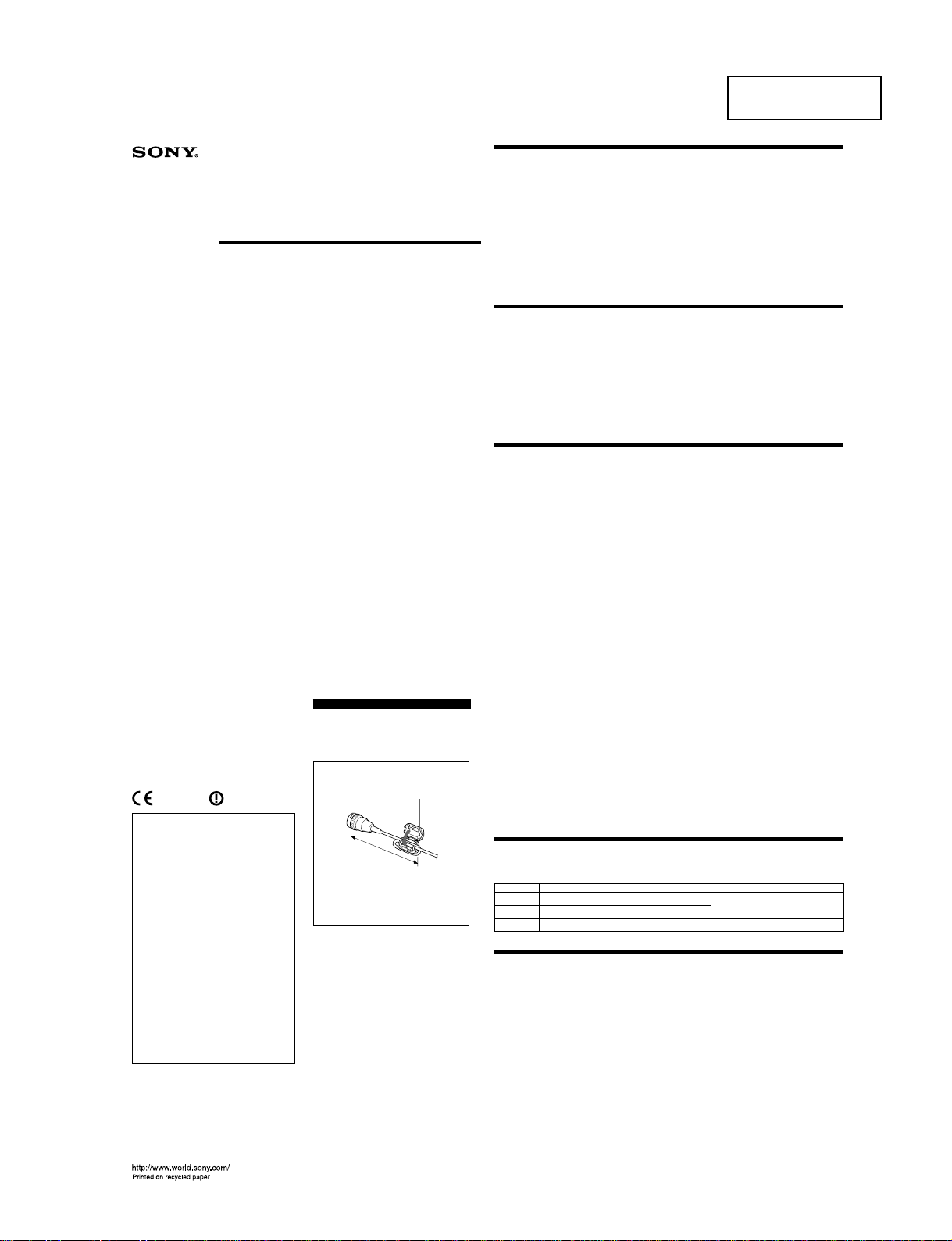
Note on the model available in Europe
When you operate the WRT-822B on the
bandwidth between 470 MHz and 566 MHz,
be sure to fix a Ferrite Clamp to the
microphone cable, near the microphone
connector as shown below.
0889
U.K. 854.125 - 862 MHz
Turkey 854.125 - 862 MHz
Spain
841.250, 841.750, 842.250, 842.750 MHz
843.250, 848.750, 849.250, 849.750 MHz
850.250, 850.750, 851.250, 851.750 MHz
Germany798 - 822 MHz
Norway 800 - 820 MHz
Luxembourg
800 - 830 MHz, 854.125 - 862 MHz
Belgium 854.125 - 862 MHz
Denmark800 - 820 MHz
France 470 - 830 MHz
Greece 800 - 820 MHz
Ireland 800 - 820 MHz
Italy 800 - 820 MHz
Portugal 800 - 820 MHz
Sweden 800 - 820 MHz
Switzerland
800 - 820 MHz
Finland 800 - 814 MHz
Iceland 800 - 814 MHz
Austria 774 - 790 MHz
Netherlands
774 - 782 MHz
Hereby, Sony Corporation, declares that this
WRT-822B is in compliance with the essential
requirements and other relevant provisions of
Directive 1999/5/EC.
Note:
In some countries additional frequency bands
may be used with the agreement of the national
authority.
Note for customers in Austria:
Before use, it is necessary to obtain
individual permission of the local
telecommunications spectrum authority.
Note for customers in Switzerland:
Before use, a request of concession for a
wireless microphone (Frequency Class 3)
has to be submitted to Bakom.
Note for customers in Finland:
To own and use, it is necessary to obtain an
individual licence of the Telecommunications
Administration Center.
Note for customers in Luxembourg:
Before any use of an equipment, the
frequencies required have to be, if necessary
according to the regulations in force,
assigned prior to usage by the “ILT”.
Note for customers in Italy:
The use of this product within Italy is subject
to article 334 of the Postal and
Telecommunications regulations.
Nota per i clienti in Italia:
L’uso del prodotto sul territorio italiano è
soggetto alle regolamentazioni del Codice
Postale e delle Telecomunicazioni art. 334.
Notes on Microphone System Operation
Overview
dry, soft cloth soon after use.
Lengthy use of the unit in such places or not
cleaning it after its use in such places may shorten
its life.
• When cleaning the unit, never use organic solvents
such as thinners or benzine, which will damage the
finish of the unit.
• The unit has been factory adjusted precisely. Do not
tamper with its internal parts or attempt to repair it.
The WRT-822B is a transmitter for a UHF
synthesized wireless microphone system to be used
for broadcast or movie production purpose. This
transmitter is suitable for Electronic News gathering
(ENG) and Electronic Field Production (EFP).
The microphone/transmitter and tuner of the wireless
microphone system are classified by frequency band.
A 24-MHz frequency band is assigned to each
microphone/transmitter and tuner model. In building a
UHF wireless microphone system, be sure to combine
a microphone/transmitter and a tuner having the same
wireless channel (frequency).
Features
The features of the WRT-822B are:
– Phase Locked Loop (PLL) synthesized system
– Compact and lightweight
– Remote battery alarm on tuner
– Operation powered by easily available batteries
– LCD for coordinated operation control
– Saved channel and input attenuation settings
– Highly reliable electronic attenuator
– Compatibility with Sony lavalier microphone
– RF carrier with tone signal
– Wide dynamic range and low noise
Error Messages
When a problem occurs, one of the following error message may appear on the display.
Messages
ERROR 11
ERROR 21
ERROR 31
Contents
An error occurred in backup memory data.
The PLL synthesized circuit is in trouble.
The battery voltage exceeds the allowable value.
•To operate with two or more channels, maintain a
distance of at least 30 cm (one ft.) between each pair
of transmitters.
For details of operation with two or more channels,
refer to the Operating Instructions for the WRR-802/
805/855/862, etc.
•Ensure that the tuners set to channels not being used
are either turned off or set to the minimum output
level.
•When powering the transmitter on or off, to keep the
noise to a minimum, set the audio output level from
the tuner or mixer to a minimum.
•Powering the transmitter on without checking the
channel selection first may interfere with the
operation of other microphones/transmitters, if the
current setting is already being used.
•To prevent noise generation, keep the microphones
and transmitters at least 3 m (10 feet) away from the
antennas when the system is operated using a group
which allows selection of up to 11 channels, and at
least 6 m (20 feet) away when using a group which
allows selection of 12 channels.
•When there is a strong interference signal around the
microphone system, such as an interference caused
by an active handyphone, noise may occur on the
microphone system.
Transmitter and modulator section
Oscillator Crystal controlled PLL
synthesizer
Type of emission F3E
Carrier frequencies Model available in USA:
470 to 608 MHz
614 to 806 MHz
Model available in Europe:
470 to 606 MHz
614 to 862 MHz
Operating frequency band
24 MHz
Refer to the “Sony Wireless
Microphone System Frequency
List” supplied with this manual.
RF power output 20 mW (50-ohm load)
Frequency stability Within ±15 kHz
Tone signal 32.768 kHz
Battery condition signal
32.782 kHz
Type of antenna
1
/
4
-wavelength wire
Pre-emphasis 50µs
Deviation ±5 kHz
(–60 dBv, 1 kHz input )
Frequency response 70 to 15,000 Hz
Signal-to-noise ratio60 dB or more (A-weighted,
modulation frequency 1 kHz,
with ±5 kHz deviation at
WRR-802)
Audio attenuator 0 to 21 dB, variable in 3-dB
steps
Input level
–60 dBv at audio attenuator 0 dB
Maximum input level
–3 dBv at audio atteuator 21 dB
Specifications Power section
Power requirements 3.0 V DC (two LR6/size AA
alkaline batteries)
Battery life Approx. 6 hours at 25°C
(77°F) with Sony LR6 alkaline
batteries
General
Operating temperature
0°C to +50°C (32°F to 122°F)
Storage temperature –30°C to +60°C
(–22°F to +140°F)
Dimensions 63 ×103 ×17 mm (w/h/d)
(2
1
/
2
×4
1
/
8
×
11
/
16
inches)
Mass Approx. 145 g (5.1 oz)
including batteries
Supplied accessories
Operating Instructions
Model available in USA (3)
Model available in Europe (4)
Sony wireless Microphone System Frequency List (1)
Soft case (1)
Ferrite clamp (supplied with CE21/24/27/30 model
only) (1)
Optional accessories
Lavalier microphones
ECM-44BC, ECM-55BC, ECM-66BC,
ECM-77BC, ECM-166BC, ECM-310BC,
ECM-350BC
Microphone cable
EC-1.5CF
Design and specifications are subject to change
without notice.
0 dBv = 1 Vrms
............................................................................................
About 70 mm
(3 inches)
Wind the cable once around the
clamp.
Ferrite clamp
(supplied with CE21/24/27/30
model only)
Contact your Sony dealer.
Use the specified batteries.
Measures