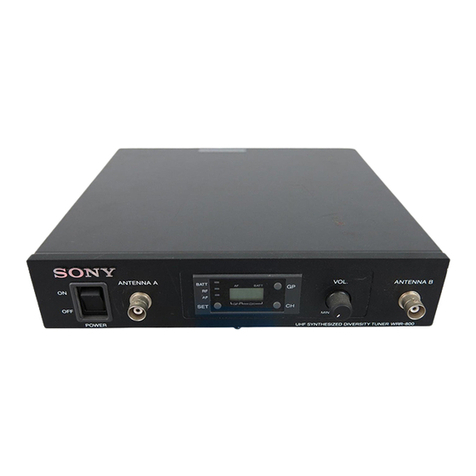
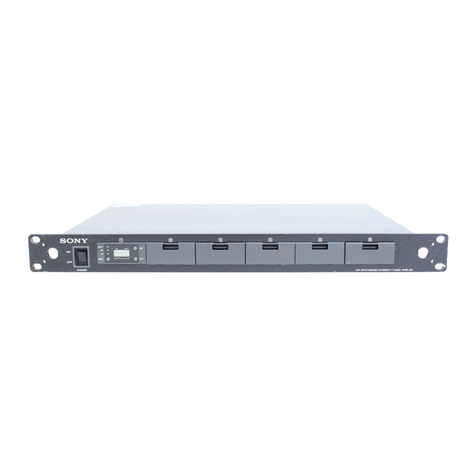
Sony MB-8N User manual

2002 Sony Corporation
Operating Instructions
Tuner Base Unit
3-619-690-13(2)
MB-8N

2
This symbol is intended to alert the user to the
presence of uninsulated “dangerous voltage”
within the product’s enclosure that may be of
sufficient magnitude to constitute a risk of
electric shock to persons.
This symbol is intended to alert the user to the
presence of important operating and
maintenance (servicing) instructions in the
literature accompanying the appliance.
This equipment has been tested and found to comply with
the limits for a Class B digital device, pursuant to Part 15 of
the FCC Rules. These limits are designed t provide
reasonable protection against harmful interference in a
residential installation. This equipment generates, uses and
can radiate radio frequency energy and, if not installed and
used in accordance with the instructions, may cause harmful
interference to radio communications. However, there is no
guarantee that interference will not occur in a particular
installation. If this equipment does cause harmful
interference to radio or television reception, which can be
determined by turning the equipment off and on, the user is
encouraged to try to correct the interference by one or more
of the following measures:
–Reorient or relocate the receiving antenna.
–Increase the separation between the equipment and
receiver.
–Connect the equipment into an outlet on a circuit different
from that to which the receiver is connected.
–Consult the dealer or an experienced radio/TV technician
for help.
You are cautioned that any changes or modifications not
expressly approved in this manual could void your authority
to operate this equipment.
IIf you have any questions about this product, you may
call;
Sony Customer Information Service Center 1-800-222-
7669 or http://www.sony.com/
Declaration of Conformity
Trade Name: SONY
Model: MB-8N
Responsible Party: Sony Electronics Inc.
Address: 16530 Via Esprillo, San Diego,
CA 92127 U.S.A.
Telephone Number: 858-942-2230
This device complies with part 15 of the FCC Rules.
Operation is subject to the following two conditions: (1)
this device may not cause harmful interference, and (2)
this device must accept any interference received,
including interference that may cause undesired
operation.
Owner’s Record
The model and serial numbers are located at the rear.
Record the serial number in the space provided below.
Refer to them whenever you call upon your Sony dealer
regarding this product.
Model No. MB-8N Serial No.
You are cautioned that any changes or modifications not
expressly approved in this manual could void your authority
to operate this equipment.
WARNING
To prevent fire or shock hazard, do not
expose the unit to rain or moisture.
To avoid electrical shock, do not open the
cabinet. Refer servicing to qualified
personnel only.
CAUTION
The apparatus shall not be exposed to dripping or splashing
and no objects filled with liquid, such as vases, shall be
placed on the apparatus.
The unit is not disconnected from the AC power source
(mains) as long as it is connected to the wall outlet, even if
the unit itself has been turned off.
For customers in the U.S.A.

3
Notice for customers in Canada
This Class B digital apparatus complies with Canadian ICES-
003.
Notice for customers in Europe
U.K. 854.125 - 862 MHz
Belgium 854.125 - 862 MHz
Luxembourg 800 - 830 MHz, 854.125 - 862 MHz
Germany 798 - 822 MHz
Norway 800 - 820 MHz
Denmark 800.100 - 819.900 MHz
France 470 - 830 MHz
Italy 800 - 820 MHz
Sweden 800 - 820 MHz
Switzerland 800 - 820 MHz
Finland 800 - 814 MHz
Iceland 800 - 814 MHz
Hereby, Sony Corporation, declares that this MB-8N is in
compliance with the essential requirements and other
relevant provisions of Directive 1999/5/EC.

4

5
Table of Contents
Precautions....................................................... 6
Overview ........................................................... 7
Features ............................................................. 7
Channel Plan ..................................................... 8
Using the CD-ROM........................................... 8
Trademarks ...................................................... 10
Location of Parts and Controls ..................... 11
MB-8N Tuner Base Unit ................................. 11
WRU-8N Tuner Unit (Option) ........................ 14
Installing and Removing a WRU-8N .............. 16
Connections ................................................... 17
Basic Connections ........................................... 17
Cascade Connection ........................................ 18
Settings ........................................................... 19
Organization of Setting Menus........................ 19
Using the Menus.............................................. 22
List of Settings ................................................ 24
Details of Settings ........................................... 27
Channel Settings .............................................. 30
Appendixes ..................................................... 32
Error Messages ................................................ 32
Rack Mounting ................................................ 32
Connector Specifications ................................. 33
Principal Specifications ................................... 34

6
Table of Contents
Precautions
On operation
• The tuner must be used within a temperature range of
0°C to 40°C (32°F to 104°F). Avoid using the tuner
for extended periods at extremely high temperatures
or placing it in direct sunlight, especially outdoors,
because this may damage the finish of the case.
Never install the tuner on or near a heat source, such
as lighting equipment or power amplifiers.
•Avoid using in very humid or dusty places, because
such use may shorten the life of the tuner.
•To avoid degradation of the signal-to-noise ratio, do
not use the tuner in noisy places or in locations
subject to vibration, such as the following:
–near electrical equipment, such as motors,
transformers or dimmers
–near air conditioning equipment or places subject
to direct air flow from an air conditioner
–near public address loudspeakers
–where adjacent equipment might knock against the
tuner
•Switching lights on or off may produce electrical
interference over the entire frequency range. Position
the tuner and the wireless microphones so that
interference is minimized.
•The tuner is precisely adjusted at the factory and no
adjustment before use is necessary. Do not touch the
inside of the tuner or try to repair it by yourself.
•Do not use the unit when its fan is not working.
Using the unit with the fan being in fault may cause a
fire.
About fan replacement, contact your Sony dealer.
On cleaning
Clean the tuner with a dry, soft cloth. Never use
thinner, benzene, alcohol or any other chemicals, since
these may damage the finish.

7
Features
LAN function
The built-in network adapter and provided 10BASE-T
connector enables a LAN connection to a computer
running the Windows operating system. Using the
supplied MB-8N Network Controller software, it is
possible to operate an efficient system for central
control of MB-8N Tuner Base Units and WRU-8N
UHF Synthesizer Tuner Units from a computer.
Modular multichannel reception
By installing optional WRU-8N UHF Synthesized
Tuner Units, you can receive up to four channels on
one MB-8N unit.
Built-in antenna divider
With a built-in antenna divider and provided with a
cascade output connector, without requiring the
connection of an antenna divider unit, the MB-8N
Tuner Base Unit can be connected in cascade. For a
maximum of four MB-8N Tuner Base Units (16
channels1)), you can build a diversity receiving system
with two antennas.
Phase Locked Loop (PLL) synthesized
system
The tuner has a refined phase locked loop (PLL)
synthesizer circuit and covers two UHF TV channels.
Preprogrammed wireless channel plan for
simultaneous multichannel operation
The tuner has many preprogrammed, easily settable
channels for simultaneous multichannel operation.
Overview
These operating instructions describe the MB-8N
Tuner Base Unit in which the WRU-8N UHF
Synthesized Tuner Unit (option) is installed.
Note
For the selectable wireless channels and frequencies,
refer to the Frequency Lists on the supplied CD-ROM.
Combining the MB-8N Tuner Base Unit and the
WRU-8N UHF Synthesized Tuner Unit (option)
provides a reliable UHF synthesized diversity tuner for
the Sony UHF wireless microphone system which uses
the frequency bands allocated for UHF TV
broadcasting.
The combination of the MB-8N and the WRU-8N
enables simultaneous use of multiple channels when
channels are selected according to the Sony channel
plan.
Installing four WRU-8N UHF Synthesized Tuner
Units will enable four-channel operation on the tuner.
In building up a UHF wireless microphone system, be
sure to combine a microphone/transmitter and a tuner
having the same TV channel number.
When using CE models of WRU-8N
A 24-MHz frequency band is assigned to the WRU-
8N, permitting it to operate on any of 189 (190 with
the CE67 model) receiving frequencies in 125-kHz
steps of Sony original channel plan or 960 receiving
frequencies in 25-kHz steps in the range of three TV
channels.
When using U models of WRU-8N
A 24-MHz frequency band is assigned to the WRU-
8N, permitting it to operate on any of 188 receiving
frequencies in 125-kHz steps of Sony original channel
plan in the range of four TV channels.
When using the AU model of WRU-8N
A 14-MHz frequency band is assigned to the WRU-
8N, permitting it to operate on any of 102 receiving
frequencies in 125-kHz steps of Sony original channel
plan in the range of TV channels 66 and 67.
........................................................................................................................................................................................................
1) When each MB-8N Tuner Base Unit has four WRU-8N
UHF Synthesizer Tuner Units installed. Note that the
receiving system consisting of the MB-8N and the AU
model ot WRU-8N allows you to simultaneously use a
maximum of 12 channels in one area.

8
Overview
Versatile display
A liquid-crystal display and LEDs provide a variety of
information, including the levels of the reception
channels, RF information and transmitter battery
condition.
Space diversity reception system
The tuner provides stable signal reception with
minimum dropout.
Tone squelch circuit for noise elimination
A built-in squelch circuit eliminates noise and signal
interference when the tuner is in signal reception
standby mode.
Compander system
A compander (compressor/expander) system enables
stabilized wireless transmission over a wide dynamic
range.
Rack mounting
The MB-8N can be mounted in an EIA standard 19-
inch rack (1U size).
Channel Plan
The tuner stores several groups of channels. (Refer to
“Overview of Channel Plan” in the Frequency Lists on
the supplied CD-ROM.)
Channel groups other than group 00 (and groups of 25-
kHz steps with CE models) are designed so that all
channels of one group can be used simultaneously
within the same UHF wireless microphone system
without causing intermodulation. It is therefore
recommended that you usually use a channel group
other than group 00 (and groups of 25-kHz steps with
CE models) unless the use of group 00 (or any group
of 25-kHz steps with CE models) is specifically
necessary.
Using the CD-ROM
The supplied CD-ROM contains the following files.
Note
To use the MB-8N Network Controller, it is necessary
to install it in your computer.
For the installation procedure, see “Installation” on the
next page.
For detailed information on the MB-8N Network Controller,
refer to the User’s Guide for the MB-8N Network
Controller.
To view a PDF file, you will require Acrobat Reader or
Adobe Reader. For details, refer to the Adobe website at:
http://www.adobe.com/
Operating conditions
The MB-8N Network Controller is designed to run on
a computer meeting the following requirements.
File
MB-8N Network
Controller
User’s Guide for
MB-8N Network
Controller
MB-8N Operating
Instructions
Frequency Lists
Content
This is a program which allows the
status of the MB-8N Tuner Base Unit
and WRU-8N UHF Synthesizer Tuner
Units to be monitored from the
computer, and also allows various
settings.
This is a PDF file that describes the
functions and usage of the MB-8N
Network Controller. You can view it on
a computer screen.
This is a copy of this manual (PDF
file). You can view it on a computer
screen.
This HTML file shows the
correspondence between channels
and frequencies. You can view it on a
computer screen.
Item
Computer
Operating system
CPU
RAM
Available hard disk
space
Monitor
Other
Requirement
IBM PC/AT compatible
Windows 98SE/Me/2000/NT 4.0 (SP6a
or later)/XP
(English display capability needed)
Pentium II, at least 400 MHz
recommended
At least 128 MB recommended
At least 100 MB recommended
At least 1024 x 768 pixel resolution
recommended
10BASE-T LAN card, CD-ROM drive

9
Installation
•If the MB-8N Network Controller is already set up,
uninstall the existing version before continuing with
the installation. (See the next section “To uninstall
the installed files”.)
•Before installing the files contained on the supplied
CD-ROM in the computer, be sure to end all the
applications you have started, if any.
•For Windows NT, 2000 or XP user, log in as
Administrator privileges.
•If you use Windows NT, a Service Pack 6a or later is
required.
1Insert the supplied CD-ROM in the computer’s
CD-ROM drive.
If the CD-ROM Autorun function is enabled
The CD-ROM starts automatically, and a message
“SONY MB-8N NetworkController InstallShield
Wizard” appears on the screen.
For details of the CD-ROM Autorun facility, refer to
Windows Help.
If the CD-ROM Autorun function is disabled
1-1 Click the Start button, then click Run....
1-2 Click the Browse button, then in the Browse
dialog box, select the CD-ROM drive.
1-3 Select “setup.exe”, then click the Open button.
This starts the CD-ROM, and a message
“SONY MB-8N NetworkController
InstallShield Wizard” appears on the screen.
If the MB-8N Network Controller is already
installed, a message asks you to uninstall the
existing version before continuing with the
installation. If this message appears, carry out
the uninstall procedure, then repeat this
installation. (See the next section “To uninstall
the installed files”.)
2Click the Next button.
A prompt message “Choose Destination Location”
appears.
3Confirm or change the destination location.
To change, click the Browse button and select the
destination location in the dialog box which
appears.
4Click the Next button.
5Select the language, then click Start Install.
The language codes enclosed in parenthesis are as
follows:
E: English
FR: French
DE: German
ES: Spanish
J: Japanese
Installation starts.
When all the necessary files have been copied to
the hard disk, a message “InstallShield Wizard
Complete” appears.
6Click the Finish button.
To uninstall the installed files
In the Windows Control Panel, select Add/Remove
Programs, and in the list choose Sony MB-8N
Network Controller, to delete it.
How to open files
To open any of the installed files, click the Start button
on the task bar, then select Programs (“All Programs”
under Windows XP) and MB-8N Network Controller
in this order. Click the desired item in the list which
appears.
MB-8N Network Controller v1.0x: The MB-8N
Network Controller (program) starts.
On how to use this program, refer to the User’s Guide
for the MB-8N Network Controller.
User’s Guide for MB-8N Network Controller: The
PDF file of the help for the MB-8N Network
Controller opens (provided that Acrobat Reader or
Adobe Reader is installed in the computer).
MB-8N Operating Instructions: The PDF file of the
MB-8N Operating Instructions opens (provided
that Acrobat Reader or Adobe Reader is installed
in the computer).
Frequency Lists: The HTML file of the Frequency
Lists opens (provided that Internet Explorer 4.0 or
later is installed in the computer).
10
Channel plan
The channel plan shown in the Frequency Lists on the
supplied CD-ROM may include currently unsupported
features.
For the latest information, refer to your Sony service
representative.
Trademarks
•Pentium is a registered trademark of Intel
Corporation or its subsidiaries in the United States
and other countries.
•Windows is a registered trademark of Microsoft
Corporation in the United States and/or other
countries.
•Adobe, Acrobat, and Adobe Reader are trademarks of
Adobe Systems Incorporated in the United States
and/or other countries.
Overview

11
Location of Parts and Controls
MB-8N Tuner Base Unit
Front panel
VOL
MIN MAX
MENU
ENTER
LOCAL
TUNER BASE UNIT
MB-8N
PHONES
ON
OFF
21 3 4
WRU-8N
ARF
DSPL
B
AF
TX BATT
GP CH
1Power switch
2VOL control
1MB-8N display (see next page) 3Blanking panels
4PHONES connector
1Power switch
This powers the unit on and off.
Note
Do not power off while the unit is communicating with
the computer.
2VOL (volume) control
This adjusts the volume of the headphones connected
to the PHONES connector.
3Blanking panels
Remove these blanking panels to install the optional
WRU-8N UHF Synthesizer Tuner Units.
4PHONES connector
Connect headphones to monitor the audio on the
WRU-8N unit selected in the headphone output slot
allocation menu.
For details, see “Assigning headphone output slots” (page
27).
WRU-8N (option)

12
1MB-8N display
1Menu name
The menu name appears in the upper row of the
display.
2T/tbuttons
Use these to select a menu item or setting (when there
is more than one). Pressing the buttons moves the
bracket cursor (“< >” or “[ ]”) to right or left, showing
the selected menu item or setting.
3MENU button
When a submenu or setting is displayed in a setting
menu, press this button to return to the previous menu.
4ENTER button
Use this to confirm a menu item or setting in a setting
menu.
For details of using setting menus, see “Using the Menus”
(page 22).
5LOCAL indicator
This lights when in local mode.
6LOCAL/REMOTE selector button
Hold this down for three seconds to switch between
local and remote modes.
Local mode: Select this mode to make and check
settings on the operating panel of this unit. (This
disables operation from the computer.)
Remote mode: Select this mode to operate this unit
from the computer connected to the 10BASE-T
connector on the rear panel. With the operating
panel of this unit, it is only possible to check
settings, and use the headphone solo function.
You can select the default mode when the unit is powered
on. For details, see “Operating mode when powered on”
(page 28).
7+/– buttons
In local mode, use these to adjust settings in a setting
menu. Each time you press a button, the value inside
the brackets changes.
These buttons cannot be used in remote mode.
8Menu items and settings
Menu items and settings appear in the lower row of the
display.
When menu items appear, an angle bracket cursor
(“< >”) shows which item is selected.
In local mode, when a setting appears, square brackets
(“[ ]”) around the value indicate that it can be changed.
These brackets act as a cursor when more than one
setting is present.
For details of setting menu operation, see “Using the
Menus” (page 22).
VOL
MIN MAX
MENU
ENTER
LOCAL
TUNER BASE UNIT MB-8N
PHONES
1Menu name
2T/tbuttons
3MENU button
4ENTER button
5LOCAL
indicator
7+/– buttons
8Menu items
and settings
6LOCAL/REMOTE
selector button
Location of Parts and Controls

13
Rear panel
ANTENNA B AUDIO OUT
IN OUT
ANTENNA B SUB AUDIO OUT 10 BASE T
~ DC IN
IN OUT
4321
1ANTENNA A, B IN/DC 9V OUT
connectors
3SUB AUDIO OUT connector
410BASE-T connector
5DC IN connector 6AC IN connector
7AUDIO OUT connectors
2ANTENNA A, B OUT connectors
1ANTENNA A, B IN/DC 9V OUT (9V DC
output) connectors (BNC type)
Connect an optional AN-820A or similar UHF antenna
to each of these.
When an AN-820A is connected, this connector
supplies 9V DC power to the booster incorporated in
the antenna. When using an antenna which does not
require a power supply, you can switch the power
output off.
For details of the 9V DC power supply, see “Voltage output
to an antenna” (page 27).
Note
Do not short-circuit this connector.
2ANTENNA A, B OUT connectors (BNC type)
These output the signals input to the ANTENNA IN
connectors. Using these connectors, you can connect
up to four of these units in cascade.
When using a cascade connection, set the RF
attenuator for the MB-8N units to which no antenna is
directly connected to “OFF.”
For details of cascade connection, see “Cascade
Connection” (page 18).
For details of the antenna RF attenuator setting, see
“Antenna RF attenuator” (page 27).
3SUB AUDIO OUT connector (D-Sub 15-pin)
This outputs the audio signals from each WRU-8N
unit.
Note
Be careful not to mistakenly connect this connector to
the computer monitor.
For details of the SUB AUDIO OUT connector pin
assignment, see “Connector Specifications” (page 33).
410BASE-T connector (RJ-45 type)
This is a 10BASE-T connector for network
connection.
Connect to a Windows computer, in order to use the
supplied MB-8N Network Controller software for
communications with the computer.
For connection to a computer, use a category 5 LAN
cable with a maximum length of 100 m (330 ft). If the
connection requires a total cable length exceeding
100 m (330 ft), use a hub between the computer and
this unit.
Use the following type of cable when:
Directly connecting the computer and this unit:
cross cable
Using a hub between the computer and this unit:
straight cable
Caution
Only connect 10BASE-T cables to the (Ethernet
network) port. Do not connect any other type of
network cable or any telephone line. Connecting
cables other than those listed above may result in an
electric current overload and could cause a
malfunction, excessive heat, or fire in the connector.
To connect the unit to the network, contact your
network manager.

14
5DC IN connector (XLR type)
Use this when operating the unit with a DC power
supply. The voltage range that can be used is +12 to
+24 V.
Note
When power is supplied through this connector, the
front panel power switch no longer controls the power
to this unit. Be sure to use a DC power supply with a
power switch, which you can use to power this unit on
and off.
For details of the DC IN connector pin assignment, see
“Connector Specifications” (page 33).
6AC IN connector
Connect to an AC power source with the supplied AC
power cord.
7AUDIO OUT connectors (XLR type)
These output the audio signals from corresponding
WRU-8N units. Connect to the audio input connectors
of a mixer, amplifier, or other equipment. You can set
the output level for each WRU-8N unit separately.
For details of the output settings, see “Audio output levels”
(page 27).
For details of the pin assignment of the AUDIO OUT
connector, see the section “Connector Specifications” (page
33).
WRU-8N Tuner Unit (Option)
1Fixing screws
These fix the WRU-8N unit to the MB-8N unit (this
unit).
2Jog dial
The jog dial has two functions, as follows.
•Press to set the setting changing mode, or to confirm
a setting (corresponds to the function of the ENTER
button).
•Turn clockwise or counterclockwise to change a
setting (corresponds to the function of the +/–
buttons).
WRU-8N
ARF
DSPL
B
AF
TX BATT
GP CH
MENU
ENTER
LOCAL
21
1Fixing screws
2Jog dial
3DSPL button
1WRU-8N display (see next page)
In local mode, use this to change a group (GP),
channel (CH), or frequency setting.
When pressed, the display flashes, and the setting can
now be changed. In this state, turning clockwise or
counterclockwise changes the setting, and pressing
once more confirms the change. In the group/channel
(GP/CH) display, repeat this operation to set both the
group (GP) and channel (CH).
In remote mode, by pressing the jog dial you can
monitor only the audio of the WRU-8N unit with the
headphone connected to the PHONES connector (solo
function).
3DSPL (display) button
Pressing this button toggles the WRU-8N display (next
page) between the group/channel (GP/CH) display and
frequency display.
Location of Parts and Controls

15
1WRU-8N display
1AF (audio output) level display
2AF (audio output) indicator
If an audio signal of the reference level or above is
output, the indicator lights, and the display appears.
3BATT (battery) indicator
4BATT (battery) display
When a transmitter has a battery alarm function, about
one hour before the battery goes dead, the display
appears, and begins to flash.
This function is effective with the following
transmitters.
•WRT-8B
• WRT-822A/822B
• WRT-805A/805B
• WRT-807A/807B
• WRT-847A/847B
• WRT-860A
•WRT-808A (available in USA only)
The time when the flashing starts depends on the type
and state of the battery used by the transmitter.
5Group/channel (GP/CH) display
This shows the group and channel of the receiving
channel. Pressing the DSPL button toggles between
the group/channel display and frequency display for
the receiving channel.
ARF
DSPL
B
AF
TX BATT
GP CH
1AF level display
2AF indicator
3BATT indicator
4BATT display
5GP/CH display
6RF level display
7RF indicator
6RF (radio frequency input) level display
7RF (radio frequency input) indicator
Of the antennas A and B, the indicator lights for that
with the better receiving conditions, appearing as a
number of segments. The number of segments
displayed depends on the radio frequency input level.
Note
During multi-channel operation or while there is
interference, the RF indicator or BATT indicator may
flash even though the desired signal is not being
received. In this case, the LCD display shows a
flashing “NOTONE,” indicating that the desired signal
is not being received.

16
Installing and Removing a WRU-8N
You can install up to four WRU-8N units in this unit.
Notes
•Be sure to power this unit off first.
•Pressing too strongly on the jog dial or indicaters on
the WRU-8N front panel may damage it. Always
press on the edges of the front panel.
•Do not touch the WRU-8N rear panel and connectors.
•Be careful of static electricity.
Installation
1Press the upper and lower tabs of the blanking
panel, and pull the lower edge forward, to remove
the blanking panel.
2Holding the sides of the WRU-8N, insert it in the
slot, and press in until the panel is flush with the
MB-8N operating panel.
3Turn the fixing screws, to fix.
Removal
1Fully loosen the fixing screws.
2Holding the fixing screws in both hands, slowly
pull out.

17
Connections
Basic Connections
The following diagram illustrates the basic
connections when using this unit alone.
ANTENNA B
AUDIO OUT
ANTENNA A
IN IN
b) b)
c)
a) ~ AC IN
MB-8N
UHF antenna
AN-820A
Mixer or amplifier
a) AC power cord (supplied)
b) 50-ohm coaxial cable (RG-5 type, RG-212 type or equivalent recommended)
c) XLR cable
UHF antenna
AN-820A

18
Cascade Connection
The following diagram illustrates the cascade
connection when using two or more of these units with
a computer.
ANTENNA B AUDIO OUT ANTENNA A
10 BASE-TOUT
OUT
IN IN
ANTENNA B AUDIO OUT ANTENNA A
10 BASE-TOUT
OUT
IN IN
ANTENNA B AUDIO OUT ANTENNA A
10 BASE-TOUT
OUT
IN IN
ANTENNA B AUDIO OUT ANTENNA A
10 BASE-T
IN IN
b) b)
b)
c)
c)
c)
c)
b)
b) b)
b) b)
d) d) d) d)
d)
a) ~ AC IN
MB-8N
a) ~ AC IN
MB-8Ne)
a) ~ AC IN
MB-8Ne)
a) ~ AC IN
MB-8Ne)
UHF antenna
AN-820A
Windows computer
Hub
Mixer
a) AC power cord (supplied)
b)50-ohm coaxial cable (RG-5 type, RG-212 type or equivalent recommended)
c) XLR cable
d)Category 5 LAN cable (straight cable not exceeding 100 m (330 ft))
e) For the MB-8N units to which no antenna is directly connected, set the
antenna RF attenuator to “OFF” (0 dB).
f) If you install the MB-8N Network Controller software on more than one
computer on the network, do not start the software on more than one
computer at a time.
UHF antenna
AN-820A
Note
When five or more of these units are cascade-
connected, distribution loss may lead to an unstable
reception.
Connections
f)

19
Settings
Once this unit is installed and the peripherals
connected, make the necessary settings.
The setting operation depends on the operation mode
of this unit, as follows.
Local mode: You can set or check settings using the
operating panel of this unit (local menu).
Remote mode: With the operating panel of this unit,
you can only check settings (remote menu). It is
not possible to change settings.
With this unit connected to a computer through a
LAN, using the supplied MB-8N Network
Controller software, you can change settings using
the software interface.
This manual describes how to carry out settings with
the operating panel of this unit.
For details of settings using the MB-8N Network Controller,
refer to the User’s Guide for MB-8N Network Controller on
the supplied CD-ROM.
Organization of Setting Menus
Local menu
When this unit is in local mode, the MB-8N display
shows “***Local Menu***,” and the setting menus
allowing settings to be changed are available.
The local menu gives access to a hierarchical tree of
menus, as shown on the next page (maximum four
levels).
You make the settings from submenus.
After purchase, when you install the WRU-8N in the
MB-8N for the first time, the following may appear on
the MB-8N display (example: WRU-8N installed in
slot 4).
In this case, select OK, and press the ENTER button.
This reads in the initial settings for the WRU-8N.
Remote menu
When this unit is in remote mode, the MB-8N display
shows “**Remote Menu**,” and you can check the
settings in the sequence shown on page 21.
For details of how to use the menus, see page 22.

20
Local menu
Local Menu
MB WRU NET ETC
MB Config
ATT DC AF MON
ANTENNA ATT
AntA AntB ALL AntA ATT [dB]
AntB ATT [dB]
Headphones
L/R
AntAB ATT [dB]
WRU Config
USR RSQ SQ
User Name
1 2 3 4
Tone&Noise SQ
1 2 3 4 ALL
TUNER1 SQ Set
T/N
TUNER2 SQ Set
T/N
TUNER3 SQ Set
T/N
TUNER4 SQ Set
T/N
TUNER SQ Set
T/N
AF LEVEL
1 2 3 4 ALL 1CH AF LEVEL
2CH AF LEVEL
3CH AF LEVEL
4CH AF LEVEL
1ch User Name
2ch User Name
3ch User Name
MB DATA CLEAR
WRU DATA CLEAR
ALL DATA CLEAR
4ch User Name
1-4CH AF LEVEL
ANT DC OUT
RF SQ Level
1 2 3 4 ALL 1ch RF SQ Lv
2ch RF SQ Lv
Network Config
HOST IP HOST Name
IP ADDRESS
Other Config
MOD CHS GP DEF
3ch RF SQ Lv
4ch RF SQ Lv
1-4ch RF SQ Lv
CH Search
1/2/3/4
DEFAULT MODE
Default Setting
MB WRU INIT
Auto GP Setting
Root menu
(First level)
Submenus
(Second level)
Submenus/Settings
(Third level)
Settings
(Fourth level)
: Root menu or submenu
: Settings
For details of how to use the menus, see page 22.
Settings
Other manuals for MB-8N
3
Table of contents
Other Sony Tuner manuals