Sony WRR-850A User manual

1
3-800-445-11(1)
S
Operating Instructions
Before operating the unit, please read this manual
thoroughly and retain it for future reference.
WRR-850A
1996 by Sony Corporation
UHF Synthesized
Diversity Tuner

2
Owner’s Record
The model and serial numbers are located at the
rear. Record the serial number in the space
provided below. Refer to these numbers
whenever you call upon your Sony dealer
regarding this product.
Model No. WRR-850A
Serial No. ________________
You are cautioned that any changes or
modifications not expressly approved in this
manual could void your authority to operate this
equipment.
WARNING
To prevent fire or shock hazard, do not
expose the unit to rain or moisture.
To avoid electrical shock, do not open the
cabinet. Refer servicing to qualified personnel
only.
Notice for customers in Canada:
Use of Sony wireless devices is regulated by
Industry Canada as described in their
Telecommunication Regulatory Circular RSS-123.
A licence is normally required. The local district
office of Industry Canada should therefore be
contacted. When the operation of the device is
within the broadcast band, the licence is issued
on no-interference, no-protection basis with
respect to broadcast signals.
Avis pour les clients au Canada:
L’usage des appareils sans-fil Sony est réglé par
l’Industrie Canada comme décrit dans leur Cahier
des Normes Radioélectriques CNR-123. Une
licence est normalement requise. Le bureau de
l’Industrie Canada doit être contacté.
Lorsque l’opération de l’appareil est dans les
limites de la bande de radiodiffusion, la licence
est émanée sur la base de non-interférence, non-
protection avec les signaux de radiodiffusion.
This symbol is intended to alert the user to
presence of uninsulated “dangerous vol-
tage” within the product’s enclosure that
may be of sufficient magnitude to constitute
a risk of electric shock to persons.
This symbol is intended to alert the user to
the presence of important operating and
maintenance (servicing) instructions in the
literature accompanying the appliance.

3
Table of Contents
Features ......................................................................................................4
Channel Plan ..............................................................................................5
Groups, Channels and Frequencies ........................................................5
42 Channel System Plan.........................................................................9
Precautions ...............................................................................................10
Location of Parts and Controls ..............................................................11
Front Panel ...........................................................................................11
Display..................................................................................................12
Rear Panel.............................................................................................13
Connections ..............................................................................................14
Basic Connections ................................................................................14
Multichannel Mode ..............................................................................15
Installation................................................................................................16
Installation of Receivers and Antennas ................................................16
Notes on Antenna Installation ..............................................................17
System Setup ............................................................................................18
System Configuration...........................................................................18
Settings......................................................................................................22
Selecting the Reception Channel..........................................................22
Setting the Muting Level ......................................................................25
Setting the Output Level.......................................................................27
Setting the Tuner Unit Number ............................................................27
Operation..................................................................................................28
Rack Mounting ........................................................................................30
Removing the Mounting Brackets........................................................31
Dimensions...........................................................................................31
Error Messages ........................................................................................32
Specifications............................................................................................33

4
The WRR-850A is a high-performance tuner for the 800-MHz-band Sony
UHF wireless microphone system which uses the frequency bands
allocated for UHF TV broadcasting. This tuner enables application of
multiple channels over unused television channels through the use of the
built-in Sony original channel plan.
Phase Locked Loop (PLL) synthesized system
The unit has a refined phase locked loop (PLL) synthesizer circuit and
covers two UHF TV channels. It operates on 94 channels over a 12-MHz
frequency.
Built-in wireless channel plan for simultaneous
multichannel operation
The WRR-850A has many preprogrammed, easily settable channels in a
simultaneous multichannel operation. One group allows setting of 94
channels. The unit also has six preset groups of channels, each of which
permits simultaneous operation of 8, 11, 13, or 19 channels without the
effects of intermodulation. There is also a channel plan for 42 channel
simultaneous operation using the 6 TV bands on UHF TV channels 64 to
69.
Twin tuners
The WRR-850A has two tuner units. You can set the tuners to different
channels and still operate both at the same time.
Versatile display
A large liquid-crystal display provides a variety of information, including
the levels of the reception channels, RF information and transmitter battery
condition.
Space diversity reception system
The WRR-850A provides stable signal reception with minimum dropout.
Adjustable muting level
You can select the muting level (15 dBµ, 25 dBµ and 35 dBµ) to meet your
specific needs.
Tone squelch circuit for noise elimination
A built-in squelch circuit eliminates noise and signal interference when the
unit is in signal reception standby mode.
Compander system
A compander (compressor/expander) system enables stabilized wireless
transmission over a wide dynamic range.
Output monitoring
You can monitor the audio output using headphones. The level is
adjustable.
1U-size EIA rack mount
The unit can be mounted in an EIA-standard 19-inch rack (1U size).
Features

5
Groups, Channels and Frequencies
Channel Plan
Notes
• Each “wireless channel” is represented by a 2-digit TV
channel number and a 2-digit number, for example: 68-23.
• The channels in each group other than group 00 can be
used simultaneously.
• When operating two or more UHF wireless microphone
systems using channels in different groups, ensure that the
systems are at least 100 m (330 feet) apart from each other.
(The same applies also when using channels in a group if
the different UHF wireless microphone systems are
installed where they are within sight of each other.)
• If there is a TV broadcasting station nearby, to avoid
possible interference with broadcasting, do not use that
station’s channel.
• The number of wireless microphone channels actually
usable in a multi-channel system may be smaller than the
normal capacity of that system if there is interference from
TV broadcasting or other RF signals.
The unit stores 11 groups of selectable channels: groups 00
(94 channels), 11 (11 ch.), 12 (8 ch.), 13 (8 ch.), A1 (19 ch.),
A2 (13 ch.), A3 (13 ch.), L1 (7 ch.), L2 (7 ch.), H1 (7 ch.),
and H2 (7 ch.). Channel groups other than group 00 are
designed so that all channels of one group can be used
simultaneously within the same UHF wireless microphone
system without causing intermodulation. It is therefore
recommended that you usually usea channel group other than
group 00 unless the use of group 00 is specifically necessary.
The following pages explain the purpose of each group, and
give the channel-frequency assignment table for each group.
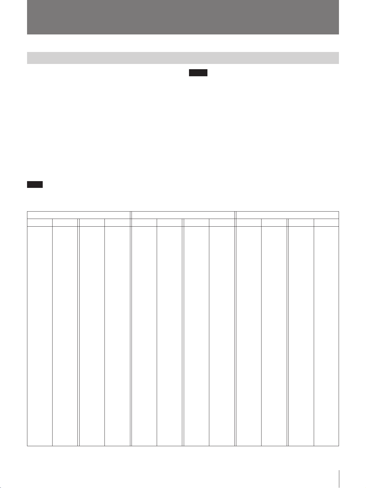
Group 00 (to receive all 94 channels)
This group receives all 94 wireless microphone channels
selected at 125-kHz intervals in a frequency band assigned
to a WRR-850A combination.
Note
When using more than one channel from group 00
simultaneously, avoid selecting adjacent channels or
channels at uniform intervals.
WRR-850A (64) WRR-850A (66) WRR-850A (68)
Channel Frequency Channel Frequency Channel Frequency Channel Frequency Channel Frequency Channel Frequency
Frequency (in MHz)
64-01
64-02
64-03
64-04
64-05
64-06
64-07
64-08
64-09
64-10
64-11
64-12
64-13
64-14
64-15
64-16
64-17
64-18
64-19
64-20
64-21
64-22
64-23
64-24
64-25
64-26
64-27
64-28
64-29
64-30
64-31
64-32
64-33
64-34
64-35
64-36
64-37
64-38
64-39
64-40
64-41
64-42
64-43
64-44
64-45
64-46
64-47
770.125
770.250
770.375
770.500
770.625
770.750
770.875
771.000
771.125
771.250
771.375
771.500
771.625
771.750
771.875
772.000
772.125
772.250
772.375
772.500
772.625
772.750
772.875
773.000
773.125
773.250
773.375
773.500
773.625
773.750
773.875
774.000
774.125
774.250
774.375
774.500
774.625
774.750
774.875
775.000
775.125
775.250
775.375
775.500
775.625
775.750
775.875
65-01
65-02
65-03
65-04
65-05
65-06
65-07
65-08
65-09
65-10
65-11
65-12
65-13
65-14
65-15
65-16
65-17
65-18
65-19
65-20
65-21
65-22
65-23
65-24
65-25
65-26
65-27
65-28
65-29
65-30
65-31
65-32
65-33
65-34
65-35
65-36
65-37
65-38
65-39
65-40
65-41
65-42
65-43
65-44
65-45
65-46
65-47
776.125
776.250
776.375
776.500
776.625
776.750
776.875
777.000
777.125
777.250
777.375
777.500
777.625
777.750
777.875
778.000
778.125
778.250
778.375
778.500
778.625
778.750
778.875
779.000
779.125
779.250
779.375
779.500
779.625
779.750
779.875
780.000
780.125
780.250
780.375
780.500
780.625
780.750
780.875
781.000
781.125
781.250
781.375
781.500
781.625
781.750
781.875
66-01
66-02
66-03
66-04
66-05
66-06
66-07
66-08
66-09
66-10
66-11
66-12
66-13
66-14
66-15
66-16
66-17
66-18
66-19
66-20
66-21
66-22
66-23
66-24
66-25
66-26
66-27
66-28
66-29
66-30
66-31
66-32
66-33
66-34
66-35
66-36
66-37
66-38
66-39
66-40
66-41
66-42
66-43
66-44
66-45
66-46
66-47
782.125
782.250
782.375
782.500
782.625
782.750
782.875
783.000
783.125
783.250
783.375
783.500
783.625
783.750
783.875
784.000
784.125
784.250
784.375
784.500
784.625
784.750
784.875
785.000
785.125
785.250
785.375
785.500
785.625
785.750
785.875
786.000
786.125
786.250
786.375
786.500
786.625
786.750
786.875
787.000
787.125
787.250
787.375
787.500
787.625
787.750
787.875
67-01
67-02
67-03
67-04
67-05
67-06
67-07
67-08
67-09
67-10
67-11
67-12
67-13
67-14
67-15
67-16
67-17
67-18
67-19
67-20
67-21
67-22
67-23
67-24
67-25
67-26
67-27
67-28
67-29
67-30
67-31
67-32
67-33
67-34
67-35
67-36
67-37
67-38
67-39
67-40
67-41
67-42
67-43
67-44
67-45
67-46
67-47
788.125
788.250
788.375
788.500
788.625
788.750
788.875
789.000
789.125
789.250
789.375
789.500
789.625
789.750
789.875
790.000
790.125
790.250
790.375
790.500
790.625
790.750
790.875
791.000
791.125
791.250
791.375
791.500
791.625
791.750
791.875
792.000
792.125
792.250
792.375
792.500
792.625
792.750
792.875
793.000
793.125
793.250
793.375
793.500
793.625
793.750
793.875
68-01
68-02
68-03
68-04
68-05
68-06
68-07
68-08
68-09
68-10
68-11
68-12
68-13
68-14
68-15
68-16
68-17
68-18
68-19
68-20
68-21
68-22
68-23
68-24
68-25
68-26
68-27
68-28
68-29
68-30
68-31
68-32
68-33
68-34
68-35
68-36
68-37
68-38
68-39
68-40
68-41
68-42
68-43
68-44
68-45
68-46
68-47
794.125
794.250
794.375
794.500
794.625
794.750
794.875
795.000
795.125
795.250
795.375
795.500
795.625
795.750
795.875
796.000
796.125
796.250
796.375
796.500
796.625
796.750
796.875
797.000
797.125
797.250
797.375
797.500
797.625
797.750
797.875
798.000
798.125
798.250
798.375
798.500
798.625
798.750
798.875
799.000
799.125
799.250
799.375
799.500
799.625
799.750
799.875
69-01
69-02
69-03
69-04
69-05
69-06
69-07
69-08
69-09
69-10
69-11
69-12
69-13
69-14
69-15
69-16
69-17
69-18
69-19
69-20
69-21
69-22
69-23
69-24
69-25
69-26
69-27
69-28
69-29
69-30
69-31
69-32
69-33
69-34
69-35
69-36
69-37
69-38
69-39
69-40
69-41
69-42
69-43
69-44
69-45
69-46
69-47
800.125
800.250
800.375
800.500
800.625
800.750
800.875
801.000
801.125
801.250
801.375
801.500
801.625
801.750
801.875
802.000
802.125
802.250
802.375
802.500
802.625
802.750
802.875
803.000
803.125
803.250
803.375
803.500
803.625
803.750
803.875
804.000
804.125
804.250
804.375
804.500
804.625
804.750
804.875
805.000
805.125
805.250
805.375
805.500
805.625
805.750
805.875

6
Group 11 (for an 11-channel system)
This group is used to simultaneously receive up to 11
wireless microphone channels selected in the frequency
band assigned to a WRR-850A combination.
Note
In a place where an 11-channel system composed of a
particular WRR-850A combination is used, you cannot
simultaneously use another 11-channel system composed of
a different WRR-850A combination.
Note
In a place where an 8-channel system composed of a
particular WRR-850A combination is used, you cannot
simultaneously use another 8-channel system composed of a
different WRR-850A combination.
Group 12 (for an 8-channel system using odd-numbered
TV channels)
This group is used to simultaneously receive up to eight
wireless microphone channels selected in the frequency
band of the odd-numbered TV channel assigned to a WRR-
850A combination.
Note
In a place where an 8-channel system composed of a
particular WRR-850A combination is used, you cannot
simultaneously use another 8-channel system composed of a
different WRR-850A combination.
Channel Plan
Frequency (in MHz)
WRR-850A (64) WRR-850A (66) WRR-850A (68)
Channel
66-05
66-14
66-25
66-41
66-47
67-12
67-16
67-30
67-37
67-40
67-42
Frequency
782.625
783.750
785.125
787.125
787.875
789.500
790.000
791.750
792.625
793.000
793.250
Channel
68-05
68-14
68-25
68-41
68-47
69-12
69-16
69-30
69-37
69-40
69-42
Frequency
794.625
795.750
797.125
799.125
799.875
801.500
802.000
803.750
804.625
805.000
805.250
Channel
64-05
64-14
64-25
64-41
64-47
65-12
65-16
65-30
65-37
65-40
65-42
Frequency
770.625
771.750
773.125
775.125
775.875
777.500
778.000
779.750
780.625
781.000
781.250
Channel
67-01
67-05
67-11
67-25
67-28
67-36
67-41
67-43
Frequency (in MHz)
WRR-850A (64) WRR-850A (66) WRR-850A (68)
Frequency
776.125
776.625
777.375
779.125
779.500
780.500
781.125
781.375
Channel
69-01
69-05
69-11
69-25
69-28
69-36
69-41
69-43
Frequency
800.125
800.625
801.375
803.125
803.500
804.500
805.125
805.375
Frequency
788.125
788.625
789.375
791.125
791.500
792.500
793.125
793.375
Channel
65-01
65-05
65-11
65-25
65-28
65-36
65-41
65-43
Group 13 (for an 8-channel system using even-numbered
TV channels)
This group is used to simultaneously receive up to eight
wireless microphone channels selected in the frequency
band of the even-numbered TV channel assigned to a WRR-
850A combination.
Channel
66-03
66-13
66-18
66-26
66-37
66-40
66-44
66-46
Frequency (in MHz)
WRR-850A (64) WRR-850A (66) WRR-850A (68)
Frequency
770.375
771.625
772.250
773.250
774.625
775.000
775.500
775.750
Channel
68-03
68-13
68-18
68-26
68-37
68-40
68-44
68-46
Frequency
794.375
795.625
796.250
797.250
798.625
799.000
799.500
799.750
Frequency
782.375
783.625
784.250
785.250
786.625
787.000
787.500
787.750
Channel
64-03
64-13
64-18
64-26
64-37
64-40
64-44
64-46

7
Group A1 (for a 19-channel system)
This group is used to simultaneously receive up to 19
channels selected in the overall frequency band of 6 TV
channels receivable by three types of tuner combinations:
WRR-850A (64), WRR-850A (66) and WRR-850A (68).
Group A2 (for a 13-channel system using odd-numbered
TV channels)
This group is used to simultaneously receive up to 13
wireless microphone channels selected in the frequency
bands of the odd-numbered TV channels receivable by three
types of tuner combinations: WRR-850A (64), WRR-850A
(66) and WRR-850A (68).
Group A3 (for a 13-channel system using even-
numbered TV channels)
This group is used to simultaneously receive up to 13
wireless microphone channels selected in the frequency
bands of even-numbered TV channels receivable by three
types of tuner combinations: WRR-850A (64), WRR-850A
(66) and WRR-850A (68).
Channel
66-02
66-24
66-29
67-16
67-18
67-39
—
—
Frequency (in MHz)
WRR-850A (64) WRR-850A (66) WRR-850A (68)
Frequency
770.625
771.500
771.875
779.000
780.125
—
—
—
Channel
68-06
68-20
68-24
68-40
69-04
69-17
69-23
69-47
Frequency
794.750
796.500
797.000
799.000
800.500
802.125
802.875
805.875
Frequency
782.250
785.000
785.625
790.000
790.250
792.875
—
—
Channel
64-05
64-12
64-15
65-24
65-33
—
—
—
Channel
67-07
67-33
67-45
—
—
—
—
Frequency (in MHz)
WRR-850A (64) WRR-850A (66) WRR-850A (68)
Frequency
776.250
778.375
781.375
—
—
—
—
Channel
69-11
69-22
69-30
69-36
69-40
69-43
69-45
Frequency
788.875
792.125
793.625
—
—
—
—
Channel
65-02
65-19
65-43
—
—
—
—
Frequency
801.375
802.750
803.750
804.500
805.000
805.375
805.625
Channel
66-06
66-32
66-44
—
—
—
—
Frequency (in MHz)
WRR-850A (64) WRR-850A (66) WRR-850A (68)
Frequency
770.125
772.250
775.250
—
—
—
—
Channel
68-10
68-21
68-29
68-35
68-39
68-42
68-44
Frequency
782.750
786.000
787.500
—
—
—
—
Channel
64-01
64-18
64-42
—
—
—
—
Frequency
795.250
796.625
797.625
798.375
798.875
799.250
799.500

8
Channel Plan
Group L1 (for a 7-channel system using even-numbered
TV channels)
This group is used to simultaniously receive up to 7 wireless
microphones. Frequency (in MHz)
Channel
64-09
64-11
64-19
64-25
64-30
64-34
64-37
Frequency
771.125
771.375
772.375
773.125
773.750
774.250
774.625
Frequency
783.125
783.375
784.375
785.125
785.750
786.250
786.625
Channel
68-09
68-11
68-19
68-25
68-30
68-34
68-37
Channel
66-09
66-11
66-19
66-25
66-30
66-34
66-37
Frequency
795.125
795.375
796.375
797.125
797.750
798.250
798.625
WRR-850A (64) WRR-850A (66) WRR-850A (68)
Group L2 (for a 7-channel system using even-numbered
TV channels)
This group is used to simultaniously receive up to 7 wireless
microphones. Frequency (in MHz)
Frequency
795.250
795.625
796.125
796.750
797.500
798.500
798.750
Channel
66-10
66-13
66-17
66-22
66-28
66-36
66-38
WRR-850A (64) WRR-850A (66) WRR-850A (68)
Frequency
771.250
771.625
772.125
772.750
773.500
774.500
774.750
Frequency
783.250
783.625
784.125
784.750
785.500
786.500
786.750
Channel
68-10
68-13
68-17
68-22
68-28
68-36
68-38
Channel
64-10
64-13
64-17
64-22
64-28
64-36
64-38
Group H1 (for a 7-channel system using odd-numbered
TV channels)
This group is used to simultaniously receive up to 7 wireless
microphones. Frequency (in MHz)
Frequency
777.125
777.375
778.375
779.125
779.750
780.250
780.625
Channel
67-09
67-11
67-19
67-25
67-30
67-34
67-37
Frequency
789.125
789.375
790.375
791.125
791.750
792.250
792.625
Channel
69-09
69-11
69-19
69-25
69-30
69-34
69-37
Frequency
801.125
801.375
802.375
803.125
803.750
804.250
804.625
WRR-850A (64) WRR-850A (66) WRR-850A (68)
Channel
65-09
65-11
65-19
65-25
65-30
65-34
65-37
Group H2 (for a 7-channel system using odd-numbered
TV channels)
This group is used to simultaniously receive up to 7 wireless
microphones. Frequency (in MHz)
WRR-850A (64) WRR-850A (66) WRR-850A (68)
Channel
69-10
69-13
69-17
69-22
69-28
69-36
69-38
Frequency
801.250
801.625
802.125
802.750
803.500
804.500
804.750
Frequency
789.250
789.625
790.125
790.750
791.500
792.500
792.750
Channel
65-10
65-13
65-17
65-22
65-28
65-36
65-38
Frequency
777.250
777.625
778.125
778.750
779.500
780.500
780.750
Channel
67-10
67-13
67-17
67-22
67-28
67-36
67-38

9
42 Channel System Plan
• If the TV channel number is even, select group L1 or L2; if it is odd, select
group H1 or H2.
An example of group combination
You can select either group for a TV channel regardless of the group
setting for other TV channels.
By combining groups L1 or L2 and H1 or H2 for models 64, 66 and 68 it
is possible to operate 42 channels simultaniously. When operating 42
channels simulaniously, you will need both the WD-820A and the WD-
880A antenna dividers.
65
H1
or
H2
7
WRR-850A (64) WRR-850A (68)
TV Channel
Group name
Number of channels
Number of simultaniously
operable channels when models
64,66 and 68 are used together. 42
WRR-850A (66)
64
L1
or
L2
7
66
L1
or
L2
7
67
H1
or
H2
7
68
L1
or
L2
7
69
H1
or
H2
7
• For further information on group settings, see “Example of 42-Channel
receiving system” on page 21.
WRR-850A (68)
TV Channel
Group Combination Example 1
Example 2
Example 3
Example 4
•
•
•
•
WRR-850A (66)
WRR-850A (64)
64
L1
L2
L1
L1
•
•
•
•
65
H1
H2
H2
H1
•
•
•
•
66
L1
L2
L1
L2
•
•
•
•
67
H1
H2
H2
H2
•
•
•
•
68
L1
L2
L1
L2
•
•
•
•
69
H1
H2
H2
H1
•
•
•
•

10
• The tuner must be used within a temperature range of 0°C to +50°C
(+32°F to +122°F). Avoid using the unit for extended periods at
extremely high temperatures or placing it in direct sunlight, as this may
damage the finish of the case. Never install the tuner on or near a heat
source, such as lighting equipment or power amplifiers.
• If you install the tuner in a rack, be sure that the rack is adequately
ventilated; inadequate rack ventilation may lead to overheating
problems.
• If the tuner is used in an environment that is humid, dusty or susceptible
to harmful gas, clean the connectors and the surface after use. If used in
such an environment for an extended period, the tuner life may be
shortened.
• Do not install the tuner near electrical equipment, such as motors,
transformers, or dimmers, since this may incur magnetic induction.
• Switching lights on or off may produce electrical interference over the
wider frequency range. Position the tuner and the wireless microphones
so that interference is minimized.
• To avoid degradation of the signal-to-noise ratio, do not use the tuner in
noisy places or in locations subject to noise or vibration, such as the
following:
— near electrical equipment, such as motors or transformers
— near air conditioning equipment or places subject to direct air flow
from an air conditioner
— near public address loudspeakers
— where adjacent equipment might knock against the tuner
Install the tuner as far as possible from sources of interference and, if
needed, provide shock absorbent material.
• Clean the tuner with a dry, soft cloth. Never use thinner, benzene,
alcohol or any other chemicals, since these may damage the finish.
Precautions

11
OUTPUT
LEVEL
CHGPMUTINGNO.
FREQ
12
S
ØON øOFF
12LEVEL
MONITOR
MIN MAX
UHF SYNTHESIZED DIVERSITY TUNER WRR-850
POWER
RF
AF
OUTPUT
LEVEL
CHGPMUTINGNO.
FREQ
RF
AF
1POWER switch
2MONITOR jack
3MONITOR LEVEL control
4MONITOR switches and indicators
6FREQ +/– buttons
7OUTPUT LEVEL button
8CH button
9GP button
0MUTING button
!¡ NO. button
5Display
Location of Parts and Controls
Front Panel
1POWER switch
Turns the power ON and OFF.
2MONITOR jack
Connects to headphones to enable monitoring of the
output signal.
3MONITOR LEVEL control
Adjusts the volume of the headphones connected to the
MONITOR jack.
4MONITOR switches and indicators
Selects tuner unit 1 or 2 for monitoring. The indicator
below the number of the selected tuner lights.
Tuner unit 1
5Display
After you turn on the power, the message “64
HELLO”, “66 HELLO” or “68 HELLO”appears,
depending on the model. When the message
disappears, the tuner changes to normal display mode.
6FREQ (frequency) +/– buttons
Sets a reception channel with a press on the NO.
button, MUTING button, GP button, CH button, and
OUTPUT LEVEL button.
The FREQ + button toggles between the CH indication
and the frequency indication.
7OUTPUT LEVEL button
Sets the output level (–20 dBm or –58 dBm).
8CH (channel) button
Changes the channel in the same group.
9GP (group) button
Changes the group of the reception channel.
0MUTING button
Sets the muting level.
!¡ NO. (number) button
Sets the tuner unit number.
Tuner unit 2
The buttons for tuner unit 2have the same functions
as those for tuner unit 1.

12
Location of Parts and Controls
Display
1Number indicator
Shows the number (1 to 99) that has been assigned to
the tuner unit.
2RF (radio frequency) lamp
Lights when the antenna reception is optimal.
3RF (radio frequency input level) indicator
Shows the strength of the input signal. The diversity
changeover is displayed when either aor bis lit.
RF
AF
88
888.8888 MHz
–20 dBm
–58 dBm
ab
OFF 11 1
1Number indicator
2RF lamp
3RF indicator
4AF indicator
6Output level indicator
5Battery indicator
7GP/CH indicator
8MUTING indicator
9AF lamp
4AF (audio frequency) indicator
Lights when an audio signal greater than the reference
level is output.
5Battery indicator
Indicates the condition of the wireless microphone
transmitter batteries. The battery indicator and the
number indicator start flashing about one hour before
the transmitter batteries go flat.
Indicator
Level more than
15 dBµ more than
25 dBµ more than
35 dBµ more than
45 dBµ
Note
The battery and number indicators only flash when the
unit is used with certain transmitters, such as the
WRT-860A. For details on compatible transmitters,
see the operating instructions of the transmitter.
6Output level indicator
Shows the output reference level.
7GP/CH (group/channel) indicator
Shows the reception channel group and respective
channel number.
Each time the FREQ + button is pressed, this indicator
switches between showing the reception channel
frequency and the channel number.
8MUTING indicator
Shows the muting level or
OFF
.
For details, see “Setting the Muting Level” on page 25.
9AF (audio frequency) lamp
Lights when an audio signal greater than the reference
level is output.

13
⁄AC IN
REMOTE (15PIN)
ANTENNA A
DO 9V OUT
IN
ANTENNA B
DO 9V OUT
IN
12
TUNER OUTPUT
Rear Panel
1ANTENNA A, B IN / DC 9 V OUT connectors
2TUNER OUTPUT connectors
3REMOTE connector
4AC power output connector
5AC IN connector
1ANTENNA A, B IN/ DC 9 V OUT (antenna A, B
input/DC power output) connectors (BNC type)
Connects to an AN-820A UHF Antenna (A/B) for
diversity reception.
If an antenna is connected directly to the tuner without
connecting with an antenna divider such as the WD-
820A, DC 9 V is supplied to the antenna’s internal
booster.
Note
Never short-circuit this connector.
2TUNER OUTPUT (tuner sound output)
connectors (XLR, 3-pin, male)
Supplies audio signals. You can connect this to the
microphone input connector or the sound input
connector of a mixer, tape recorder, or similar
equipment.
3REMOTE connector (D-sub, 15-pin)
Connects to a display unit (not supplied) that shows
the numbers for 12 channels and is equipped with an
AF lamp and an RF lamp.
4AC power output connector
Supplies a maximum of 300 W power to a peripheral
piece of equipment, regardless of whether the POWER
switch is set to ON or OFF.
5AC IN connector
Connects to an AC power source with the supplied AC
power cable.
132
1: GND
2: HOT
3: COLD

14
⁄AC IN
REMOTE (15PIN)
ANTENNA A
DO 12V OUT
IN
ANTENNA B
DO 12V OUT
IN 12
TUNER OUTPUT
AN-820A UHF antenna
WRR-850A
to AC power
Antenna B Antenna A
Connections
Basic Connections
Note
Make sure to use a pair of antennas.
Once you have made all the connections, use the plus/minus (+/–) buttons
and the OUTPUT LEVEL button to set the reference level of the TUNER
OUTPUT connectors in accordance with the input level of the connected
equipment (mixer, amplifier, etc.).
For details on the reference level setting, see “Setting the Output Level”
on page 27.
to input connector of
a mixer, amplifier, etc.

15
Multichannel Mode
Connect the signal output connectors of each tuner directly to the mixer.
When the tuner is in the multichannel mode, you can set up the mixer for a
variety of operations, such as allocating channels for particular tasks,
limiting the number of microphones used, operating microphones
separately, etc.
In addition to the connections below, you can combine the WRR-850A
tuner with tuners WRR-820A or WRR-840A.
Example of using
four antennas
AN-820A
WD-820A
WD-820A
50-ohm BNC terminators
WRR-850A
WRR-850A
WRR-850A
WRR-850A
WRR-850A
WRR-850A
50-ohm BNC
terminators

16
Installation of Receivers and Antennas
• Small hall with a stage width of 10 meters (33 feet): Install an antenna on both sides of the stage.
• Large hall with a stage width of 15 meters (50 feet) or larger: Install two antennas parallelly (1 to 2 meters [3 1/3
to 6 2/3feet] apart) on the side of the stage closest to the sound control room.
Installation
Setup in halls where the sound control room is behind the seating area
Install the antennas on one side
of the stage with the receiver in
the sound control room.
Antennas
Coaxial cable
Sound control room
Receiver unit
Setup in halls where the sound control room is behind the seating area and far from the stage
Install the receiver unit close to
the antennas at the side of the
stage to minimize the length of
the antenna (coaxial) cable.
Audio cable
Receiver unit
Antennas
Sound control room

17
,
,
,
y
y
,Q¢
,,yy
,y
Setup in halls where the sound control room is at the side of the stage
Sound control room
Receiver unit
Antenna
• Use a pair of antennas. Separate them by 1 to 2
meters (3 1/3to 6 2/3feet). Mount the antennas so that
a wireless microphone or transmitter can transmit
signals directly to the antennas.
• Do not install the antennas in the following
locations:
– inside the ceiling or walls
– near windows, metal boards, or electric equipment
(lighting fixtures, motors, elevators, breakers, etc.)
electronic equipment (computers, dimmers,
televisions, TV cameras, etc.)
– where people or other equipment might interfere
with them
• The recommended coaxial cable for connecting the
antennas to the tuner and antenna divider is a 5D-2V
(50 ohm or higher). You can also use a 5C-2V (75
ohm or higher).
Signal loss: 5D-2V 50 m: 12.5 dB
100 m: 25 dB
5C-2V 50 m: 13.5 dB
100 m: 27 dB
• The coaxial cable should be as short as possible. The
signal loss increases as the cable length increases,
which has a greater impact than the difference
between 50 ohms and 75 ohms.
Notes on Antenna Installation
Separate the antennas by 1 to 2
meters (3 1/3to 6 2/3feet).
Mount the antennas more than 10 centimeters
(4 in.) away from the ceiling or an adjacent wall.
Mount the antennas as far as
possible from electric equipment
(e.g., elevators, computers, etc.) to
prevent radio wave interference.
Mount the antennas as far as
possible from windows to prevent
interference from outside.
Mount the antennas about half way
between the floor and the ceiling or
at about 5 meters (16 ft. 8 in.) in
height.

18
When using 19 channels
System Setup
System Configuration
Connection of tuners in series allows for 19 channel
simultaneous operation. If the WD-880A antenna
divider is used, a maximum of 42 channels become
available.
Use a pair of antennas. Do not operate multiple
wireless microphones or transmitters on the same
channel.
WRR-850A
WD-820A
for four antennas
AN-820A
When using two channels When using four channels
AN-820A
WRR-850A WD-820A
WRR-850A
for four antennas
AN-820A
When using six channels
WRR-850A
WD-820A
for four antennas
AN-820A
When combining with an existing system
AN-820A
WD-820A
WRR-850A
WRR-840A
WRR-820A
for four antennas

19
Example of 11-channel receiving system (using Group 11)
Cascade connection
AN-820A AN-820A
WD-820A
WRR-850A
WD-820A
WRR-850A
Example of 8-channel receiving system (using Group 12 or 13)
WD-820A
WRR-850A
AN-820A AN-820A

20
Example of 13-channel receiving system (using Group A2 or A3)
Example of 19-channel receiving system (using Group A1)
Installation
AN-820A AN-820A
WD-820A WD-820A
WRR-850A (64)
WRR-850A (66)
WRR-850A (68)
TV Channel 64: 3 channels +
TV Channel 66: 3 channels TV Channel 68: 7 channels
TV Channel 64: 3 channels
+
TV Channel 66: 3 channels
+
TV Channel 68: 7 channels
Cascade
WD-820A
AN-820A AN-820A
Cascade connection Cascade connection
WD-820A WD-820A
TV Channel 64: 5 channels +
TV Channel 66: 2 channels TV Channel 66: 4 channels +
TV Channel 68: 4 channels TV Channel 68: 4 channels
TV Channel 64: 5 channels
+
TV Channel 66: 6 channels
+
TV Channel 68: 8 channels
WRR-
850A (64)
WRR-
850A (66)
WRR-
850A (66)
WRR-
850A (68)
WRR-
850A (68)
Table of contents
Other Sony Tuner manuals

Sony
Sony WRU-806B User manual

Sony
Sony WRR-805A User manual

Sony
Sony XT-V70 User manual

Sony
Sony ST-S320 User manual

Sony
Sony MICROFILM ST-707RM User manual

Sony
Sony ST-88 User manual

Sony
Sony STR-NX1 User manual

Sony
Sony XDRF1HD - HD Radio Tuner User manual

Sony
Sony FDL-3105 User manual

Sony
Sony ST-S800ES User manual