Sony WRR-800A User manual

3-860-929-31 (1)
Operating Instructions
WRR-800A
© 1997 by Sony Corporation [AU]
UHF Synthesized
DiversityTuner

2
WARNING
To prevent fire or shock hazard, do not expose the unit
to rain or moisture.
To avoid electrical shock, do not open the cabinet.
Refer servicing to qualified personnel only.
On operation
• The unit must be used within a temperature range of 0°C to
40°C (32°F to 104°F). Avoid using the unit for extended
periods at extremely high temperatures or placing it in
direct sunlight, especially outdoors because this may
damage the finish of the case. Never install the unit on or
near a heat source, such as lighting equipment or power
amplifiers.
• To avoid using in very humid or dusty places, because
such use may shorten the life of the unit.
• To avoid degradation of the signal-to-noise ratio, do not
use the unit in noisy places or in locations subject to
vibration, such as the following:
— near electrical equipment, such as motors, transformers
or dimmers
— near air conditioning equipment or places subject to
direct air flow from an air conditioner
— near public address loudspeakers
— where adjacent equipment might knock against the unit
• Switching lights on or off may produce electrical
interference over the entire frequency range. Position the
unit and the wireless microphones so that interference is
minimized.
• The unit is precisely adjusted at the factory and no
adjustment before use is necessary. Do not touch the
inside of the unit or try to repair it by yourself.
On cleaning
Clean the unit with a dry, soft cloth. Never use thinner,
benzene, alcohol or any other chemicals, since these may
damage the finish.
Precautions

3
Precautions............................................................... 2
Overview ...................................................................3
Features ................................................................. 3
System Configuration ........................................... 4
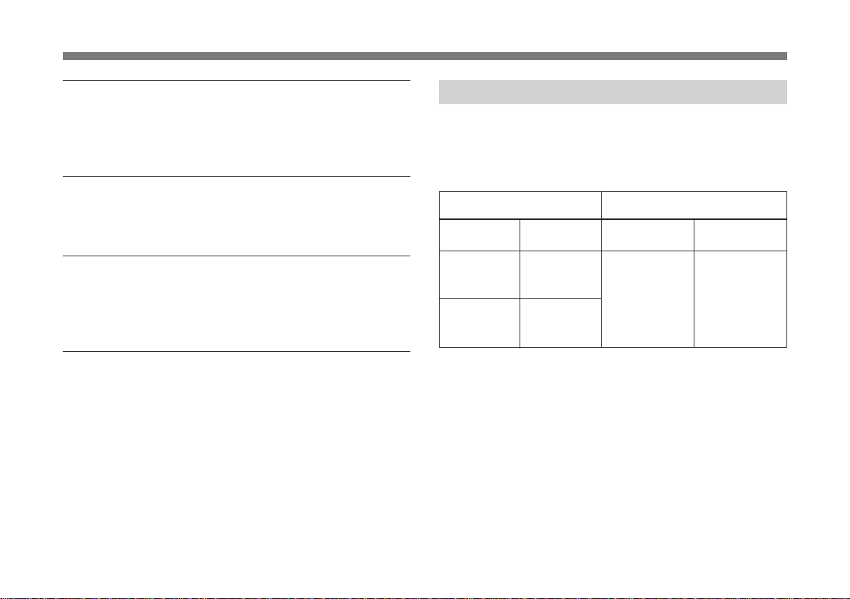
Wirelss Channels Selectable .................................. 5
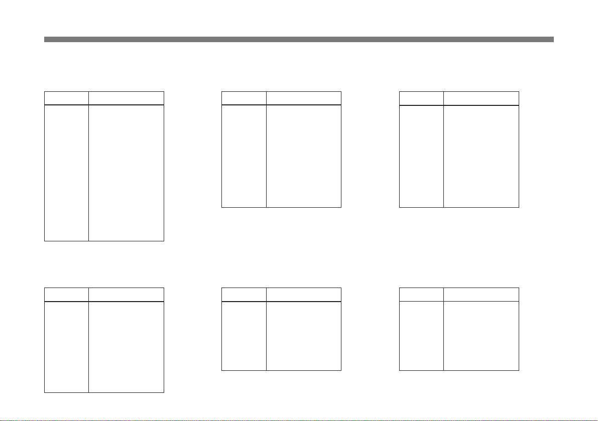
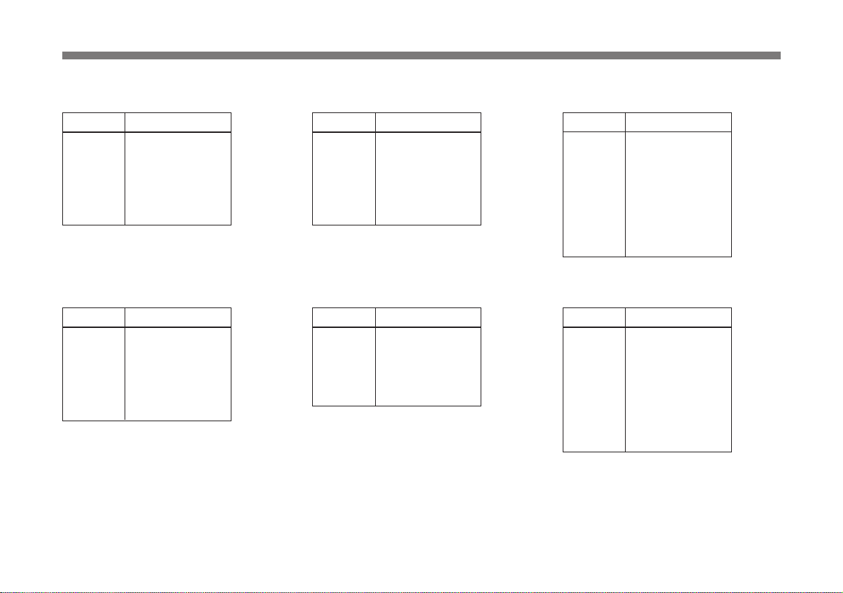
Wireless Channel Lists ......................................... 6
Location of Parts and Controls............................... 9
Front Panel ............................................................ 9
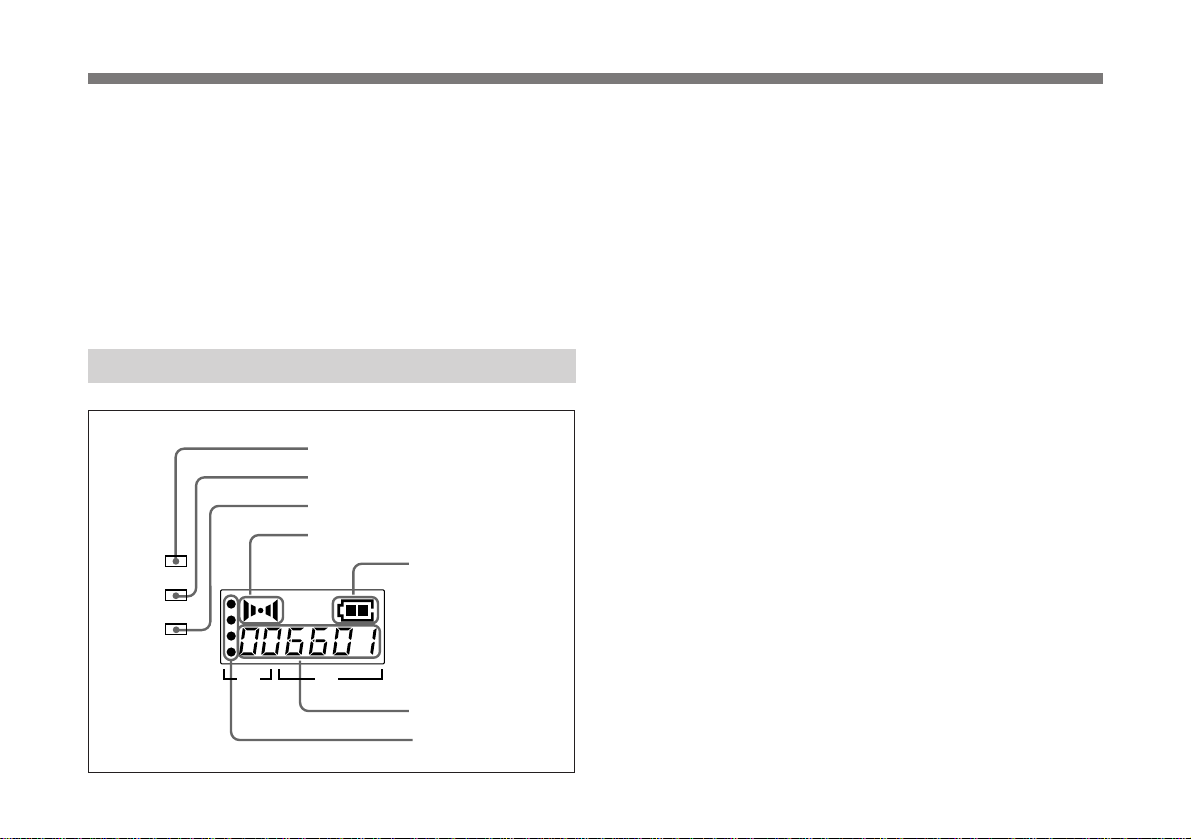
Display ................................................................ 10
Rear Panel ........................................................... 11
Operation ................................................................12
Muting Functions ................................................ 13
Channel Setting......................................................13
Error Messages ......................................................15
Specifications.........................................................16
Table of Contents Overview
The WRR-800A is a reliable UHF synthesized diversity
tuner for the 800-MHz-band Sony UHF wireless
microphone system which uses the frequency bands
allocated for UHF TV broadcasting.
This unit is designed to enable simultaneous use of multiple
channels when channels are selected according to the Sony
channel plan.
Features
Phase Locked Loop (PLL) synthesized system
The WRR-800A has a refined phase locked loop (PLL)
synthesizer circuit and covers two UHF TV channels. It
operates on 102 channels over a 14-MHz frequency.
Preprogrammed wireless channel plan for
simultaneous multichannel operation
The WRR-800A has many preprogrammed, easily settable
channels in a simultaneous multichannel operation. One
group allows setting of 102 channels. The unit also has 12
preset groups of channels, each of which permits ,
simultaneous operation of 5, 6, 8, 9 or 12 channels without
the effects of intermodulation.

4
Versatile display
A liquid-crystal display provides a variety of information,
including the levels of the reception channels, RF
information and transmitter battery condition.
Space diversity reception system
The WRR-800A provides stable signal reception with
minimum dropout.
Tone squelch circuit for noise elimination
A built-in squelch circuit eliminates noise and signal
interference when the WRR-800A is in signal reception
standby mode.
Compander system
A compander (compressor/expander) system enables
stabilized wireless transmission over a wide dynamic range.
Overview
System Configuration
The unit can be used with a Sony UHF synthesized wireless
microphone or UHF synthesized transmitter among the
models listed in the table below.
Sony 800 MHz-band system models
Frequency band Model name
TV channel Transmitter or
microphone
Frequency
(MHz) Tuner
66 792.250 to
798.500 WRT-800A (66)
WRT-805A (66)
WRT-810A (66)
WRT-820A (66)
WRT-830A (66)
WRT-860A (66)
WRT-867A (66)
WRR-800A (66)
WRR-801A (66)
WRR-810A (66)
WRR-820A (66)
WRR-840A (66)
WRR-850A (66)
WRR-860A (66)
67 799.250 to
805.500

5
The unit stores 13 groups of selectable channels:
groups 00 (102 channels), 11 (12 channels), 12 (9 channels),
13 (9 channels), A1 (8 channels), A2 (6 channels),
A3 (6 channels), L1 (6 channels), L2 (6 channels),
M1 (6 channels), M2 (5 channels), H1 (8 channels) and
H2 (8 channels).
Channel groups other than group 00 are designed so that all
channels of one group can be used simultaneously within the
same UHF wireless microphone system without causing
intermodulation. It is therefore recommended that you
usually use a channel group other than group 00 unless the
use of group 00 is specifically necessary.
Each “wireless channel” is represented by a 2-digit TV
channel number and a 2-digit number, for example: 66-23.
Note
To eliminate interference or noise, please note the
following.
• Do not use two or more wireless microphones or
transmitters whose wireless channels are the same.
• If there is a TV broadcasting station nearby, to avoid
possible interference from its broadcasting, do not use that
station’s channel.
• The number of wireless microphone channels actually
usable in a multi-channel system may be smaller than the
normal capacity of that system if there is interference from
TV broadcasting or other RF signals.
• When operating two or more UHF wireless microphone
systems using the same wireless channel in the same
group, ensure that the systems are at least 100 m (330
feet)1) apart as far as they are installed within sight of each
other.
1) The distance depends on the operating environment and conditions.
............................................................................................................................................................................................................................................................
Wirelss Channels Selectable

6
Wireless Channel Lists
Group 00: All channel access
Use only for a one-channel system or to scan for open
channels.
66-01 792.250
66-02 792.375
66-03 792.500
66-04 792.625
66-05 792.750
66-06 792.875
66-07 793.000
66-08 793.125
66-09 793.250
66-10 793.375
66-11 793.500
66-12 793.625
66-13 793.750
66-14 793.875
66-15 794.000
66-16 794.125
66-17 794.250
66-18 794.375
66-19 794.500
66-20 794.625
66-21 794.750
66-22 794.875
66-23 795.000
66-24 795.125
66-25 795.250
66-26 795.375
67-27 802.500
67-28 802.625
67-29 802.750
67-30 802.875
67-31 803.000
67-32 803.125
67-33 803.250
67-34 803.375
67-35 803.500
67-36 803.625
67-37 803.750
67-38 803.875
67-39 804.000
67-40 804.125
67-41 804.250
67-42 804.375
67-43 804.500
67-44 804.625
67-45 804.750
67-46 804.875
67-47 805.000
67-48 805.125
67-49 805.250
67-50 805.375
67-51 805.500
WL Channel Frequency (MHz) WL Channel Frequency (MHz) Channel Frequency (MHz) Channel Frequency (MHz)
67-01 799.250
67-02 799.375
67-03 799.500
67-04 799.625
67-05 799.750
67-06 799.875
67-07 800.000
67-08 800.125
67-09 800.250
67-10 800.375
67-11 800.500
67-12 800.625
67-13 800.750
67-14 800.875
67-15 801.000
67-16 801.125
67-17 801.250
67-18 801.375
67-19 801.500
67-20 801.625
67-21 801.750
67-22 801.875
67-23 802.000
67-24 802.125
67-25 802.250
67-26 802.375
66-27 795.500
66-28 795.625
66-29 795.750
66-30 795.875
66-31 796.000
66-32 796.125
66-33 796.250
66-34 796.375
66-35 796.500
66-36 796.625
66-37 796.750
66-38 796.875
66-39 797.000
66-40 797.125
66-41 797.250
66-42 797.375
66-43 797.500
66-44 797.625
66-45 797.750
66-46 797.875
66-47 798.000
66-48 798.125
66-49 798.250
66-50 798.375
66-51 798.500
Wirelss Channels Selectable

7
Group A2: 6-channel group
Use when TV channel 66 is on the air. Group A3: 6-channel group
Use when TV channel 67 is on the air.
WL Channel Frequency (MHz)
66-06 792.875
66-15 794.000
66-21 794.750
66-32 796.125
66-46 797.875
66-50 798.375
WL Channel Frequency (MHz)
67-06 799.875
67-15 801.000
67-21 801.750
67-32 803.125
67-46 804.875
67-50 805.375
Group 11: 12-channel group
Use when TV channels both 66 and
67 are available.
WL Channel Frequency (MHz)
66-02 792.375
66-07 793.000
66-17 794.250
66-19 794.500
66-35 796.500
66-43 797.500
67-08 800.125
67-19 801.500
67-33 803.250
67-39 804.000
67-42 804.375
67-46 804.875
Group 12: 9-channel group
Use when TV channel 66 is on the air.
WL Channel Frequency (MHz)
67-01 799.250
67-03 799.500
67-11 800.500
67-16 801.125
67-23 802.000
67-27 802.500
67-41 804.250
67-44 804.625
67-50 805.375
Group 13: 9-channel group
Use when TV channel 67 is on the air.
WL Channel Frequency (MHz)
66-01 792.250
66-03 792.500
66-11 793.500
66-16 794.125
66-23 795.000
66-27 795.500
66-41 797.250
66-44 797.625
66-50 798.375
Group A1: 8-channel group
Use when both TV channels 66 and
67 are available.
WL Channel Frequency (MHz)
66-02 792.375
66-04 792.625
66-12 793.625
66-24 795.125
67-02 799.375
67-29 802.750
67-35 803.500
67-44 804.625

8
Group L1: 6-channel group
Use when TV channel 67 is on the air.
Group L2: 6-channel group
Use when TV channel 67 is on the air.
Group M1: 6-channel group
Use when TV channel 67 is on the air.
Group M2: 5-channel group
Use when TV channel 67 is on the air.
Group H1: 8-channel group
Use when TV channel 66 is on the air.
Group H2: 8-channel group
Use when TV channel 66 is on the air.
WL Channel Frequency (MHz)
66-01 792.250
66-03 792.500
66-09 793.250
66-14 793.875
66-18 794.375
66-21 794.750
WL Channel Frequency (MHz)
66-02 792.375
66-04 792.625
66-10 793.375
66-15 794.000
66-19 794.500
66-22 794.875
WL Channel Frequency (MHz)
66-31 796.000
66-33 796.250
66-39 797.000
66-44 797.625
66-48 798.125
66-51 795.500
WL Channel Frequency (MHz)
66-32 796.125
66-34 796.375
66-40 797.125
66-45 797.750
66-49 798.250
WL Channel Frequency (MHz)
67-03 799.500
67-05 799.750
67-11 800.500
67-16 801.125
67-26 802.375
67-35 803.500
67-38 803.875
67-42 804.375
WL Channel Frequency (MHz)
67-06 799.875
67-08 800.125
67-12 800.625
67-22 801.875
67-25 802.250
67-33 803.250
67-40 804.125
67-45 804.750
Wirelss Channels Selectable

9
Front Panel
ON ANTENNAA VOL. ANTENNA B
SET
GP
CH
OFF
POWER
BATT
RF
AF
MIN MAX
AF BATT
GP CH
1POWER switch
2ANTENNA A, B connectors
3Display
4SET button
5GP button
7VOL. Control
6CH button
1POWER switch
Turns the power on and off.
2ANTENNA A, B (antenna A, B) connectors (BNC
type)
Connect the supplied antennas.
3Display
Displays the status of this unit and the groups and channels
assigned to the unit.
For details, see the following section “Display”.
4SET button
Press to change the group or channel.
Location of Parts and Controls

10
5GP (group) button
Press to change the group or to display frequencies.
6CH (channel) button
Press to change the channel in a group.
7VOL. (volume) control
Adjusts the volume of the tuner output.
Display
AF BATT
GP CH
BATT
RF
AF
1BATT indicator
2RF indicator
3AF indicator
4AF indication
1BATT (battery) indicator
5BATT (battery) indication
Indicate the condition of the wireless microphone
transmitter batteries. The indicator and indication start
flashing about one hour before the transmitter batteries go
flat.
2RF (radio frequency) indicator
7RF (radio frequency) indications
The indicator lights and the indications (dots) appear when
the antenna reception is optimal. Depending on the RF input
level, the number of dots changes.
3AF (audio frequency) indicator
4AF (audio frequency) indication
The indicator lights and the indication appears when the
audio output level is higher than the reference level.
6GP/CH (group/channel) indication
Shows the reception channel group and respective channel
number.
Pressing the GP button changes this indication to the
frequency indication.
Location of Parts and Controls
7RF indications
6GP/CH indication
5BATT indication

11
TUNER OUTPUT
LINE LEVEL 0dBm
DC IN 9V
¥
Rear Panel
1TUNER OUTPUT connector
3Cord clamp
1TUNER OUTPUT (tuner sound output) connector
(ø6.3 phone balanced (1/4inch TRS))
Supplies audio signals. You can connect this to the audio
input connector of a mixer, amplifier, or similar equipment.
2DC IN 9V (9 V DC power input) connector
Connect the supplied AC power adaptor.
3Cord clamp
Attaches the cord of the AC power adaptor.
2DC IN 9V connector

12
+
–
5
34
1
2
1Connect the supplied antennas and make the antenna
tips point upward.
2Connect the supplied AC power adaptor to the DC IN
9V connector and an audio mixer or amplifier to the
TUNER OUTPUT connector.
3Turn the POWER switch on.
Note
Turn the POWER switch on after reducing the volume
of the equipment connected to the TUNER OUTPUT
connector. Otherwise, noise will be heard when the
POWER switch is turned on.
4Set the reception channel.
For details on setting the channels, see page 13.
5Turn on the wireless microphone or transmitter.
Use the wireless microphone or transmitter to which the
same channel is assigned as to this unit.
If noise is heard
Depending on the environment where the system is
installed, outside noise or radio wave may disrupt the
transmission of certain channels.
To select a channel under this circumstance, turn off the
wireless microphone or transmitter. Then select a channel at
which the RF indicator is off. (A channel free from noise or
radio wave interference is selected.) Set the same channel on
the microphone or transmitter.
ANTENNA A, B
Audio mixer, amplifier
AC power adaptor
UHF synthesized
transmitter
UHF
synthesized
wireless
microphone
Operation
DC IN 9V
TUNER OUTPUT

13
Muting Functions
This unit has the following three muting functions, which
work in combination.
(1) Muting by RF input level
As sufficient S/N for the audio output may not be obtained if
no RF signal is received or the RF input level is low, the
audio output can be muted when the RF input level falls
below the muting level.
(2) Tone squelch
The audio output is obtained only when the unit receives an
RF signal which includes a specified tone signal. The audio
output is muted to eliminate noise which may be heard when
the transmitter is turned on/off or the unit receives an
interference RF signal.
(3) Noise squelch
The audio output is muted to eliminate noise which may be
heard when there is such excessive interference RF signal
that the tone squelch does not work.
Channel Setting
Take the following precautions to prevent interference and
noise.
• Do not simultaneously use two or more microphones and
transmitters that are set to the same channel.
• When simultaneously using two or more tuners, always set
the tuners to different channels within the same group
(other than group 00).
• Separate the reception antennas and the transmitter by
more than 3 meters (9 feet 11 inches).
1Turn the POWER switch on.
The message “AS 66” appears on the display, and then
the current status of this unit is displayed.
1 2,3,4 3 4
(Continued)

14
Channel Setting
The CH indication shows the lowest frequency channel
of the selected group. For group 00, however, the
channel selected last is displayed.
Releasing the buttons automatically cancels the group
selection mode, and the currently displayed group is
selected.
4While holding down the SET button, press the CH
button to select a channel.
Similar to step 3, each time you press the CH button,
the CH indication changes in the order shown in the
group and reception channel list. (See “Wireless
Channel Lists” on page 6.)
If you press the CH button when the last channel of the
selected group is displayed, the first channel of the
group will be displayed.
Selecting the reception channel by frequency
Press the GP button.
This changes the GP/CH indication to a frequency
indication.
GP CH GP CH
Note
Turn the POWER switch on after reducing the volume
of equipment connected to the TUNER OUTPUT
connector. Otherwise, noise will be heard when the
power is turned on.
2Press the SET button and hold it down.
The unit changes to the group and channel selection
mode.
3While holding down the SET button, press the GP
button to select a group.
Each time you press the GP button, the GP indication
changes as shown in the following figure. To change the
indication continuously, press and hold down the GP
button.
GP CH GP CH

15
Apart from the normal indications, the following error
messages may appear on the display.
To change a frequency, press the CH button while
keeping the SET button pressed. (A higher frequency
will be displayed.)
Press the GP button again to change the frequency
indication back to a GP/CH indication.
5If the desired channel or frequency is displayed, release
the SET button and CH button.
The selected channel is set.
To store the selected group and channel
Leave the indication unchanged for 5 seconds.
The group and channel set in the procedure explained above
are stored in memory.
GP CH GP CH
Error Messages
Meaning Remedy
Err 01
Message
An error has occurred in
the backup memory data. The memory data is
initialized. Reset the
group and channel
settings.
Contact your nearest
Sony dealer.
The PLL-synthesized
circuit has a malfunction.
Err 02
NO TONE As no tone signal is
available or a tone signal
other than 32.768 kHz is
being received, the audio
signal output is muted.
The transmitter’s tone
signal is in trouble.
Contact your nearest
Sony dealer. If you are
using a WRT-810A
wireless microphone, a
“NO TONE” message
appears when you turn
off the AF switch, but
this is normal.

16
Tuner
Reception type 110KF3E
Circuit system Dual conversion superheterodyne
Reception frequencies
792.250 to 805.500 MHz
Local oscillatorsCrystal controlled PLL synthesizer
Selectivity 60 dB or more (at ±250 kHz detuned)
Spurious rejection ratio
70 dB or more
Image rejection ratio
70 dB or more
Muting level 30 dBµ1)
Antenna connectors
BNC-R type (2), 50 ohms
Frequency response
100 to 15,000 Hz ±3 dB
De-emphasis 50 µsec
Signal-to-noise ratio
30 dB or more at an A-weighted RF input
level of 20 dBµ
60 dB or more at an A-weighted RF input
level of 60 dBµ
(±5.0 kHz deviation at 1 kHz modulation)
Distortion 1% or less (±40 kHz deviation at 1 kHz
modulation)
Tone signal frequency
32.768 kHz
Output level 0 dBm2) (±16 kHz deviation at 1 kHz
modulation)
(–20 dBm (±5 kHz deviation at 1 kHz
modulation))
Output impedance
150 ohms
Output connector
ø6.3 phone balanced (1/4inch TRS)
1) 0 dBµ=1 µV
2) 0 dBm=0.775 Vrms (600 ohms loaded)
General
Power requirements
9 V DC
Current consumption
Approx. 500 mA
Operating temperature
0°C to 40°C (32°F to 104°F)
Storage temperature
–20°C to +55°C (–4°F to +131°F)
Dimensions 218 ×44 ×210 mm
(8 5/8×1 3/4×8 3/8inches) (w/h/d)
Mass Approx. 1.6 kg (57 oz)
Accessories supplied
AC power adaptor (1)
Antennas (2)
Operating Instructions (1)
Design and specifications are subject to change without
notice.
Specifications
Printed in Japan
Other manuals for WRR-800A
2
Table of contents
Other Sony Tuner manuals

Sony
Sony ST-S444ES User manual

Sony
Sony MB-8N Installation and operation manual

Sony
Sony XT-100HD User manual

Sony
Sony WRR-805A User manual

Sony
Sony ST-J88B User manual

Sony
Sony MB-8N User manual

Sony
Sony ST-EX880 User manual

Sony
Sony XDRF1HD - HD Radio Tuner User manual

Sony
Sony MB-806A User manual

Sony
Sony WRU-806B User manual