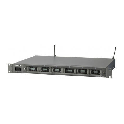
Sony MB-806A User manual

1999 Sony Corporation
Operating Instructions
Manual de Instrucciones
Mode d’emploi
Wireless Channel Lists
Listas de canales inalámbricos
Listes des canaux sans fil
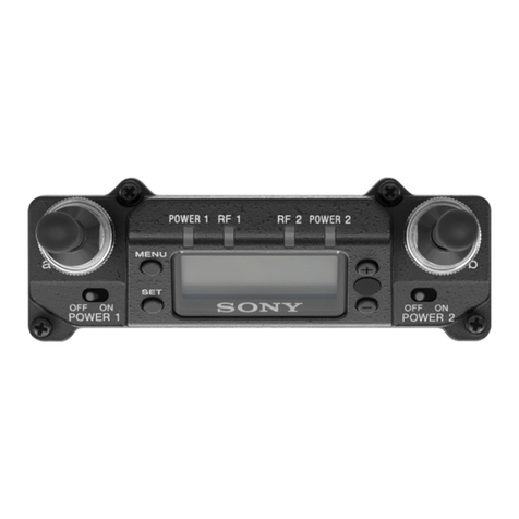
Tuner Base Unit
3-867-235-13(1)
MB-806A
US
ES
FR
[U]

Owner’s Record
The model and serial numbers are located at the rear.
Record the serial number in the space provided below.
Refer to them whenever you call upon your Sony dealer
regarding this product.
Model No. MB-806A Serial No.
You are cautioned that any changes or modifications not
expressly approved in this manual could void your authority
to operate this equipment.
WARNING
To prevent fire or shock hazard, do not
expose the unit to rain or moisture.
To avoid electrical shock, do not open the
cabinet. Refer servicing to qualified
personnel only.
This symbol is intended to alert the user to the
presence of uninsulated “dangerous voltage”
within the product’s enclosure that may be of
sufficient magnitude to constitute a risk of
electric shock to persons.
This symbol is intended to alert the user to the
presence of important operating and
maintenance (servicing) instructions in the
literature accompanying the appliance.
English
English

1(US)
Table of Contents
Precautions....................................................... 1
Overview ........................................................... 2
Features ............................................................. 2
System Configuration........................................ 2
Location of Parts and Controls....................... 3
Front Panel ........................................................ 3
Dispaly .............................................................. 3
Rear Panel ......................................................... 4
Installing a WRU-806A/WRU-806B
Tuner Unit.......................................................... 5
Connections ..................................................... 6
Basic Connection............................................... 6
Connection for Multichannel Operation ........... 6
Channel Setting................................................ 7
Automatic Search and Setting of Available
Channels....................................................... 8
Operation ........................................................ 10
Muting Functions ............................................ 11
Error Messages .............................................. 12
Rack Mounting ............................................... 12
Specifications................................................. 13
Wireless Channel Lists................................. L-1
Precautions
US
English
On operation
•The tuner must be used within a temperature range of
0°C to 40°C (32°F to 104°F). Avoid using the tuner
for extended periods at extremely high temperatures
or placing it in direct sunlight, especially outdoors,
because this may damage the finish of the case.
Never install the tuner on or near a heat source, such
as lighting equipment or power amplifiers.
•Avoid using in very humid or dusty places, because
such use may shorten the life of the tuner.
•To avoid degradation of the signal-to-noise ratio, do
not use the tuner in noisy places or in locations
subject to vibration, such as the following:
–near electrical equipment, such as motors,
transformers or dimmers
–near air conditioning equipment or places subject
to direct air flow from an air conditioner
–near public address loudspeakers
–where adjacent equipment might knock against the
tuner
•Switching lights on or off may produce electrical
interference over the entire frequency range. Position
the tuner and the wireless microphones so that
interference is minimized.
•The tuner is precisely adjusted at the factory and no
adjustment before use is necessary. Do not touch the
inside of the tuner or try to repair it by yourself.
On cleaning
Clean the tuner with a dry, soft cloth. Never use
thinner, benzene, alcohol or any other chemicals, since
these may damage the finish.
2(US)
Versatile display
A liquid-crystal display provides a variety of
information, including the levels of the reception
channels, RF information and transmitter battery
condition.
Space diversity reception system
The tuner provides stable signal reception with
minimum dropout.
Tone squelch circuit for noise elimination
A built-in squelch circuit eliminates noise and signal
interference when the tuner is in signal reception
standby mode.
Compander system
A compander (compressor/expander) system enables
stabilized wireless transmission over a wide dynamic
range.
Rack mounting
The MB-806A can be mounted in an EIA standard 19-
inch rack (1U size).
Overview
These operating instructions describe the MB-806A
Tuner Base Unit in which the optional WRU-806A/
WRU-806B UHF Synthesized Tuner Unit is installed.
The unit is a reliable UHF synthesized diversity tuner
for the Sony UHF wireless microphone system which
uses the frequency bands allocated for UHF TV
broadcasting.
This tuner is designed to enable simultaneous use of
multiple channels when channels are selected
according to the Sony channel plan.
Installing six WRU-806A
/WRU-806B
UHF
Synthesized Tuner Units will enable six-channel
operation on the tuner.
For the selectable wireless channels and frequencies, see
“Wireless Channel Lists” on page L-1 (for WRU-806A
users) or refer to “Wireless Microphone System Frequency
List” supplied with the WRU-806B (for WRU-806B users).
Features
Phase Locked Loop (PLL) synthesized
system
The tuner has a refined phase locked loop (PLL)
synthesizer circuit and covers two UHF TV channels.
It operates on 94 channels over a 12-MHz frequency
(WRU-806A) or 188 channels over a 24-MHz
frequency (WRU-806B).
Preprogrammed wireless channel plan for
simultaneous multichannel operation
The tuner has many preprogrammed, easily settable
channels for simultaneous multichannel operation. One
group allows setting of 188 channels. The tuner also
has 9 preset groups of channels, each of which permits
simultaneous operation without the effects of
intermodulation.
Modular multichannel reception
By installing optional WRU-806A
/WRU-806B
UHF
Synthesized Tuner Units, you can receive up to six
channels on one MB-806A unit.

3(US)
CH
GP
ON
OFF
POWER
+
–
GP CH
12 3 45 6
BATTAF
RF
Front Panel
1POWER switch
2GP button
4+ button
5– button
6Display
3CH button
1POWER switch
Turns the power on and off.
2GP (group) button
To change the group, press the + or – button while
holding this button down.
3CH (channel) button
To change the channel in a group, press the + or –
button while holding this button down.
4+ button
To go to a higher group or channel, press this button
while holding the GP or CH button.
Press this button changes the indication from GP/CH
to frequency.
Location of Parts and Controls
5– button
To go to a lower group or channel, press this button
while holding the GP or CH button.
6Display
Displays the status of the tuner and the group and
channel assigned to the unit.
For details, see the following section “Display”.
7Blank panels
Remove these panels to install optional WRU-806A
/
WRU-806B
UHF Synthesized Tuner Units.
1AF (audio frequency) indicator
2AF (audio frequency) level indications
The indicator lights and the indications appear when
the audio output level is higher than the reference
level.
3BATT indicator
7RF indicator
1AF indicator
2AF level indications
4BATT indication
5GP/CH indication
Display
3BATT (battery) indicator
4BATT (battery) indication
Indicate the condition of the wireless microphone
transmitter batteries. The indicator and indication
appear and start flashing about one hour before the
transmitter batteries go flat.
The time at which flashing begins will depend on the
type of battery used in the transmitter, and its
condition.
5GP/CH (group/channel) indication
Shows the reception channel group and respective
channel number.
Pressing the + button changes this indication to the
frequency indication.
6RF (radio frequency) level indications
7RF (radio frequency) indicator
The indicator lights and the indications (dots) appear
when the antenna reception is optimal. Depending on
the RF input level, the number of dots changes.
6RF level indications
GP CH
BATTAF
RF
7Blank panels

4(US)
ANTENNA B TUNER OUTPUT MIX OUTPUT
IN(DC 9V OUT)
ATT
0
6
10dB
AC IN
OUTPUT
LEVEL
LINE
–20dBm
MIC
–58dBm
⁄
ANTENNA A
IN(DC 9V OUT)
ATT
010dB
5 4 3 2 1
Rear Panel
3AC IN connector
4OUTPUT LEVEL switch
5MIX OUTPUT connector
6TUNER OUTPUT connectors
1ANTENNA A, B IN/DC 9V OUT connectors
2ANTENNA A, B ATT switches
1ANTENNA A, B IN/DC 9V OUT (antenna A, B
input/DC power output) connectors (BNC type)
Connect the supplied antenna or an optional AN-820A
UHF Antenna. To connect two of these units, these
connectors are connected to the ANTENNA OUT
connectors of the WD-820A UHF Antenna Divider.
When the AN-820A is connected, 9 V DC power is
supplied to the antenna’s internal booster through these
connectors.
Note
Never short-circuit these connectors.
2ANTENNA A, B ATT (attenuation) switches
Select the RF attenuation as 0 dB or 10 dB.
Usually set the switches to 0 dB. If noise generates or
sound discontinues due to interference, set the
switches to 10 dB.
It is recommended that you set the switches as follows
depending on the antennas connected to the
ANTENNA A, B IN/DC 9V OUT connectors.
Using the supplied antenna: 0 dB
Using an optional AN-820A UHF Antenna (with a
WD-820A Antenna Divider): 10 dB when the coaxial
cable (5D-2V, RG-212/U or equivalent) connecting the
antennas and tuner is 30 m (100 feet) or less, or 0 dB
when the cable is over 30 m (100 feet)
3AC IN connector
Connects to an AC power source with the supplied AC
power cord.
4OUTPUT LEVEL switch
Selects the mixed output level and tuner output level as
–20 dBm or –58 dBm.
Set this switch according to the input level of the
equipment connected to the unit.
5MIX OUTPUT connector (XLR type)
Supplies mixed audio signals of six tuner units. You
can connect this to the audio input connector of a
mixer, amplifier or similar equipment.
6TUNER OUTPUT (tuner sound output)
connectors (XLR type)
Each connector supplies the audio signal from the
corresponding tuner unit. You can connect this to the
audio input connector of a mixer, amplifier, or similar
equipment.
Location of Parts and Controls

5(US)
Up to six WRU-806A
/WRU-806B
UHF Synthesized
Tuner Units can be installed.
Notes
•Be sure to power this unit off before installing the
WRU-806A
/WRU-806B
.
•The buttons and display on the front panel of the
WRU-806A
/WRU-806B
may be damaged if they are
gripped too strongly. Always hold the WRU-806A
/
WRU-806B
by the side.
•Do not touch the connectors on the rear panel of the
WRU-806A
/WRU-806B
.
•Be careful of static electricity.
Installing a WRU-806A
/WRU-806B
1Hold the WRU-806A
/WRU-806B
by the side and
insert into the slot. Push in until you hear a click.
2To install two or more units, detach the necessary
number of blank panels by pushing in the top and
bottom tabs of each panel and pulling the panel
out. Then do step 1 for each unit.
Installing a WRU-806A
/WRU-806B
Tuner Unit
Removing a WRU-806A
/WRU-806B
On the bottom panel of the unit, locate the lever
corresponding to the slot where the WRU-806A
/WRU-
806B
is installed and pull the lever forward. The
WRU-806A
/WRU-806B
is ejected from the slot.
Bottom Panel
Lever

6(US)
A
B
A
B
Connections
Basic Connections
Connection for Multichannel Operation
Antenna
(supplied)
AN-820A UHF
Antenna
ANTENNA B IN ANTENNA A IN MB-806A
TUNER
OUTPUT MIX OUTPUT
Connect output A or B
to a mixer or an
amplifier.
AC IN
Power cord
(supplied) To AC power source
or
When using 1 to 6 channels
AN-820A UHF Antenna
WD-820A UHF
Antenna Divider
ANTENNA B IN
ANTENNA A IN
MB-806A
ANTENNA B IN
ANTENNA A IN
TUNER OUTPUT MIX OUTPUT
MB-806A
ANTENNA B IN ANTENNA A IN
TUNER OUTPUT MIX OUTPUT
MB-806A
When using 7 to 22 channels
Notes
•Make sure to use a pair of antennas.
•Make the antenna tips point upward.
To AC power
source
To AC power source
To AC power source
Power cord
(supplied)
Power cord
(supplied)
Power cord
(supplied)
Power cord
(supplied)
To AC power source
ANTENNA B IN ANTENNA A IN
TUNER OUTPUT MIX OUTPUT
MB-806A
To AC power source
ANTENNA B IN ANTENNA A IN
TUNER OUTPUT MIX OUTPUT Connect output A
or B to a mixer or
an amplifier.

7(US)
Take the following precautions to prevent interference
and noise.
•If there is a TV broadcasting station nearby, to avoid
possible interference from its broadcasting, do not
use that station’s channel.
•When simultaneously using two or more tuners,
always set the tuners to different channels within the
same group (other than group 00).
1Turn the POWER switch on.
The model version number such as “U 62” or
“U66” appears on the display, and then the current
tuner status is displayed.
Note
Turn the POWER switch on after reducing the
volume of equipment connected to the TUNER
OUTPUT connector. Otherwise, noise will be
heard when the power is turned on.
Channel Setting
2Press and hold down the GP button, and press the
+ or – button to select a group.
Each time you press the + or – button, the GP
indication changes as shown in the following
figure. To change the indication continuously,
press and hold down the + or – button.
The CH indication shows the lowest frequency
channel of the selected group. For group 00,
however, the channel selected last is displayed.
Releasing the buttons automatically cancels the
group and channel selection mode, and the
currently displayed group is selected.
12,3,4
3,4
2
ON
OFF
POWER
1
CH
GP +
–
GP CH
BATTAF
RF
GP CH GP CH
+–
Display example of WRU-806A (U68 model)
GP CH GP CH
+–
Display example of WRU-806B (U66 model)

8(US)
3Press and hold down the CH button, and press the
+ or – button in 3 seconds to select a channel.
Similar to step 2, each time you press the + or –
button, the CH indication changes in the order
shown in the group and reception channel list.
See “Wireless Channel Lists” on page L-1 (for WRU-
806A users) or refer to “Wireless Microphone System
Frequency List” supplied with the WRU-806B (for
WRU-806B users).
If you press the + button when the last channel of
the selected group is displayed, the first channel of
the group will be displayed.
Selecting the reception channel by frequency
Press the + button.
This changes the GP/CH indication to a frequency
indication.
To change a frequency, press the + or – button
while keeping the CH button pressed. (A higher or
lower frequency will be displayed.)
Press the + button again to change the frequency
indication to a GP/CH indication.
4If the desired channel or frequency is displayed,
release the CH button and + or – button.
The selected channel is set.
To store the selected group and channel
Leave the indication unchanged for 1 second.
The group and channel set in the procedure explained
above are stored in memory.
Automatic Search and Setting of
Available Channels
When you use the MB-806A Base Unit in a multi-
channel operation system, you can assign available
channels to all tuner units by operating the first tuner
unit only.
Note
Auto channel assignment function is available only
when the tuner base unit holds the tuner units in the
same TV channels.
1Power off all wireless microphones and
transmitters.
2On the first tuner unit, select the group to be used.
3Press the CH button on the first tuner unit and hold
it down for 3 seconds.
The first tuner unit searches for available channels
in the selected group, and available channels in the
group are so assigned to all tuner units
automatically that two or more tuner units may not
use the same channel.
After automatic setting, you can adjust the groups
and channels of individual tuner units.
Notes
•Do not use group 00.
•If no channels are available, “NO CH” is displayed
and channel setting is aborted.
Channel Setting
+
–
Display example of WRU-806B (U66 model)
GP CH GP CH
+
–
Display example of WRU-806B (U66 model)
GP CH GP CH

9(US)
When using two MB-806A Base Units
When you use two base units, proceed as follows to
ensure that the two tuner units do not use the same
channel settings.
1Follow the procedure explained above to set the
group and channel of the first base unit.
2Power on the wireless microphones or transmitters
after adjusting them to the channels of each tuner
unit.
Note
If the microphones or transmitters are not powered
on, the two tuner units may use the same channel
twice.
3On the first tuner unit of the second base unit, set
the same group as selected on the first base unit.
4Press the CH button of the first tuner unit on the
second base unit and hold it down for 3 seconds.
Available channels in the same group (channels
not used by the first base unit) are automatically
set on the first tuner unit and the other tuner units
on the second base unit.
Note
If automatic channel setting does not function well for
the second base unit (due to poor reception), set
channels manually for the second base unit.

10(US)
Connect the output signals to a mixer or an
amplifier (see page 6).
UHF synthesized
wireless
microphone UHF synthesized
transmitter
Operation
1Turn the POWER switch on.
Note
Turn the POWER switch on after reducing the
volume of the equipment connected to the TUNER
OUTPUT connector. Otherwise, noise will be
heard when the POWER switch is turned on.
2Set the reception channel.
For details on setting the channels on the tuner, see
“Channel Setting” on page 7.
3Turn on the wireless microphone or transmitter.
Use the wireless microphone or transmitter to
which the same channel is assigned as to the tuner.
If noise is heard
Depending on the environment where the system is
installed, outside noise or radio wave may disrupt the
transmission of certain channels.
To select a channel under this circumstance, turn off
the wireless microphone and transmitter. Then select a
channel at which the RF indicator is off. (A channel
free from noise or radio wave interference is selected.)
Set the same channel on the microphone or transmitter.
1 2
3
+
–
1) The distance depends on the operating environment and
conditions.
Note
To eliminate interference or noise, please note the
following.
•Do not use two or more wireless microphones or
transmitters whose wireless channels are the same.
•Separate the reception antennas and the transmitter by
more than 3 m (9 feet 11 inches).
•The number of wireless microphone channels
actually usable in a multi-channel system may be
smaller than the normal capacity of that system if
there is interference from TV broadcasting or other
RF signals.
•When operating two or more UHF wireless
microphone systems using the same wireless channel
in the same group, ensure that the systems are at least
100 m (330 feet)1) apart as far as they are installed
within sight of each other.
..........................................................................................................................................................................................................

11(US)
Muting Functions
This tuner has the following three muting functions,
which work in combination.
(1) Muting by RF input level
As sufficient S/N for the audio output may not be
obtained if no RF signal is received or the RF input
level is low, the audio output can be muted when the
RF input level falls below the muting level.
(2) Tone squelch
The audio output is obtained only when the tuner
receives an RF signal which includes a specified tone
signal. The audio output is muted to eliminate noise
which may be heard when the transmitter is turned on/
off or the tuner receives an interference RF signal.
(3) Noise squelch
The audio output is muted to eliminate noise which
may be heard when there is such excessive
interference RF signal that the tone squelch does not
work.
To turn off the muting functions
While holding down the GP and CH buttons, turn the
POWER switch to ON. All indications momentarily
appear, then go off. “OFF” is then displayed. This
procedure cancels all three muting functions at the
same time.
To turn on the muting functions
Turn the POWER switch to OFF, then to ON again.
The three muting functions are activated at the same
time.

12(US)
Apart from the normal indications, the following error
messages may appear on the display.
Message Meaning Remedy
Err 01 An error has occurred in the backup
memory data. Contact your nearest Sony dealer.
Err 02 The PLL-synthesized circuit has a
malfunction. Contact your nearest Sony dealer.
NO TONE As no tone signal is available or a
tone signal other than 32.768 kHz is
being received, the audio signal
output is muted.
Make sure that the transmitter is turned on. If it is, then the
problem lies in the transmitter’s tone signal generator or the
tuner’s tone squelch circuit. Contact your nearest Sony dealer.
If you are using a WRT-810A wireless microphone, a “NO
TONE” message appears when you turn off the AF switch, but
this is normal.
Operation
2
Pin
Foot
Error Messages
1
Rack
Remove the pins inside the feet
with a small screwdriver or similar
tool.
Bottom panel
Screws
Tuner
Rack Mounting
1Remove the feet of the tuner before mounting it on
a rack.
2Mount the tuner on the rack using screws that are
at least 12 mm (1/2inches) long and that match the
diameter of the screw holes on the rack.

13(US)
........................................................................................................................................................................................
Tuner (with WRU-806A
or WRU-806B
)
Reception type Space diversity
Circuit system Dual conversion superheterodyne
Operating frequency range (MB-806A alone)
758 to 806 MHz
Reception frequencies
Refer to the Operating Instructions
supplied with the WRU-806A or
WRU-806B, respectively.
Local oscillators Crystal controlled PLL synthesizer
Selectivity 60 dB or more (at ±250 kHz
detuned)
Spurious rejection ratio
70 dB or more
Image rejection ratio
60 dB or more
Muting level 30 dBµ1)
Antenna connectors
BNC-R type (2), 50 ohms
Frequency response
100 to 15,000 Hz ±3 dB
De-emphasis 50 µs
Signal-to-noise ratio
40 dB or more at an A-weighted
RF input level of 20 dBµ
60 dB or more at an A-weighted
RF input level of 60 dBµ
(±5 kHz deviation at 1 kHz
modulation)
Distortion 1% or less (±40 kHz deviation at
1 kHz modulation)
Tone signal frequency
32.768 kHz
Output level
LINE –20 dBm2) (±5 kHz deviation at
1 kHz modulation)
MIC –58 dBm (±5 kHz deviation at
1 kHz modulation)
Mix output level
LINE –20 dBm (±5 kHz deviation at
1 kHz modulation)
MIC –58 dBm (±5 kHz deviation at
1 kHz modulation)
Output impedance 150 ohms
Output connectors XLR-3-32 type
Specifications
General
Power requirements
120 V AC, 60 Hz
Power consumption
30 W
Power supply for antenna boosters
9 V DC (max. 100 mA)
Operating temperature
0°C to 40°C (32°F to 104°F)
Storage temperature
–20°C to +55°C (–4°F to +131°F)
Dimensions 482 ×44 ×300 mm
(19 ×1 3/4×11 7/8inches) (w/h/d)
Mass Approx. 3.6 kg (7 lb 15oz)(without
tuner units)
Accessories supplied
AC power cord (1)
Antennas (2)
Operating Instructions (1)
Design and specifications are subject to change
without notice.
1) 0 dBµ=1 µVEMF
2) 0 dBm=0.775 Vrms (600 ohms loaded)

ADVERTENCIA
Para prevenir el riesgo de incendios o de
electrocución, no exponga la unidad a la
lluvia ni a la humedad.
Para evitar descargas eléctricas, no abra
la unidad. En caso de avería, solicite el
servicio de personal cualificado
únicamente.
Español

1(ES)
Indice
Precauciones.................................................... 1
Vista general..................................................... 2
Detalles.............................................................. 2
Configuración del sistema ................................. 2
Ubicación de las partes y controles............... 3
Panel frontal ...................................................... 3
Visualizador....................................................... 3
Panel trasero ...................................................... 4
Instalación de unidad de sintonizador
WRU-806A/WRU-806B ............................. 5
Conexiones ....................................................... 6
Conexiones básicas ........................................... 6
Conexión para el funcionamiento de múltiples
canales .......................................................... 6
Ajuste de canal................................................. 7
Búsqueda automática y ajuste de canales
disponibles.................................................... 8
Funcionamiento ............................................. 10
Funciones de silenciamiento ........................... 11
Mensajes de error .......................................... 12
Instalación en un mueble .............................. 12
Especificaciones ............................................ 13
Listas de canales inalámbricos .................... L1
Precauciones
ES
Español
Para el funcionamiento
• El sintonizador debe utilizarse a temperaturas de
entre 0ºC y 40ºC. No utilice el sintonizador durante
largos períodos de tiempo a temperaturas muy altas ni
lo instale donde quede expuesto a los rayos del sol,
especialmente en exteriores, porque puede dañarse la
terminación de la caja.
No instale el sintonizador en o cerca de una fuente de
calor, por ejemplo el equipo de luces o
amplificadores de potencia.
• Evite utilizar en lugares muy húmedos o con polvo
ya que puede acortarse la vida útil del sintonizador.
• Para evitar el deterioro en la relación de señal a
ruido, no utilice el sintonizador en lugares con mucho
ruido o expuestos a vibraciones, por ejemplo:
–cerca de equipos eléctricos, por ejemplo motores,
transformadores o reductores de intensidad
–cerca de equipos de aire acondicionado o lugares
expuestos a la circulación de aire del
acondicionador de aire
–cerca de altavoces de aviso al público
–donde un equipo que esté cerca puede golpear
contra el sintonizador
• El encendido y apagado de las luces puede provocar
una interferencia eléctrica sobre toda la gama de
frecuencias. Instale el sintonizador y los micrófonos
inalámbricos de tal forma que esta interferencia sea
mínima.
• El sintonizador se ha ajustado precisamente en
fábrica y no es necesario hacer ajustes antes de su
uso. No toque el interior del sintonizador ni trate de
repararlo por su cuenta.
Para la limpieza
Limpie el sintonizador con un paño suave y seco. No
utilice diluyente de pintura, bencina, alcohol u otros
productos químicos porque pueden dañar la
terminación.

2(ES)
Vista general
Este manual de instrucciones describe la unidad
base de sintonizador MB-806A en la que se ha
instalado la unidad de sintonizador con sintetización
UHF WRU-806A/WRU-806B.
El aparato es un sintonizador de diversidad con
sintetización UHF para el sistema de micrófono
inalámbrico UHF de Sony que utiliza las bandas de
frecuencias asignadas para la transmisión de TV en
UHF.
Este sintonizador fue diseñado para utilizar
simultáneamente múltiples canales cuando se
seleccionan los canales de acuerdo al plan de canales
de Sony.
Se pueden instalar hasta seis unidades WRU-806A/
WRU-806B de sintonización con sintetización UHF
para un funcionamiento de seis canales en el
sintonizador.
Para los canales inalámbricos y frecuencias que pueden
seleccionarse, vea las “Listas de canales inalámbricos” en
la página L-1 (para usuarios de WRU-806A) o consulte la
“Lista de frecuencias del sistema de micrófono
inalámbrico” que viene con el WRU-806B (para los
usuarios del WRU-806B).
Detalles
Sistema sintetizado con bucle cerrado de
fase (PLL)
El sintonizador tiene un circuito sintetizador de bucle
cerrado de fase (PLL) refinado que abarca dos canales
de TV en UHF. Funciona en 94 canales en la
frecuencia de 12 MHz (WRU-806A) o 188 canales en
la frecuencia de 24 MHz (WRU-806B).
Plan de canales inalámbricos pre-programados para
funcionamiento simultáneo en múltiples canales
El sintonizador tiene muchos canales pre-programados
que pueden ajustarse fácilmente para un
funcionamiento simultáneo en múltiples canales. Un
grupo puede ajustar 188 canales. El sintonizador
también tiene 9 grupos prefijados de canales, cada uno
de los cuales puede operar simultáneamente sin que
sufra los efectos de la intermodulación.
Recepción modular de múltiples canales
Mediante la instalación de las unidades WRU-806A/
WRU-806B de sintonizador con sintetización UHF se
pueden recibir hasta seis canales en una unidad MB-
806A.
Pantalla versátil
Una pantalla de cristal líquido ofrece una información
variada que incluye los niveles de los canales de
recepción, información de RF y estado de la pila del
transmisor.
Sistema de diversión de diversidad espacial
El sintonizador tiene una recepción de señal estable
con mínima caída.
Circuito silenciador de tono para
eliminación de ruido
Un circuito silenciador incorporado elimina el ruido y
la interferencia de señales cuando el sintonizador está
en el modo de espera de recepción de señales.
Sistema compresor/expansor
El sistema compresor/expansor permite realizar
transmisiones estabilizadas sobre una amplia gama dinámica.
Instalación en un mueble
El MB-806A puede instalarse en un mueble normal
EIA de 19 pulgadas (tamaño 1U).

3(ES)
GP CH
BATTAF
RF
1Indicador de frecuencia de audio AF
2Indicaciones de frecuencia de nivel de audio AF
Se enciende el indicador y aparece las indicaciones
cuando el nivel de salida del audio es más alto que el
nivel de referencia.
1Interruptor principal POWER
2Botón GP
Panel frontal
1Interruptor principal POWER
Conecta y desconecta la alimentación.
2Botón de grupo GP
Para cambiar el grupo oprima el botón + o – mientras
mantiene oprimido este botón.
3Botón de canal CH
Para cambiar el canal en un grupo, oprima el botón + o
– mientras mantiene oprimido este botón.
4Botón +
Para ir a un grupo o canal más alto oprima este botón
mientras mantiene oprimido el botón GP o CH.
Oprima este botón para cambiar la indicación de GP/
CH a frecuencia.
Ubicación de las partes y controles
5Botón –
Para ir a un grupo o canal más bajo oprima este botón
mientras mantiene oprimido el botón GP o CH.
6Visualizador
Muestra el estado del sintonizador y el grupo, y el
canal asignado a la unidad.
Para más detalles, lea la sección “Visualizador”.
7Paneles vacíos
Desmonte estos paneles para instalar las unidades
WRU-806A/WRU-806B de sintonizador con
sintetización UHF.
Visualizador
3Indicador de pila BATT
4Indicación de pila BATT
Indica el estado de las pilas del transmisor de
micrófono inalámbrico. El indicador y la indicación
aparecen y empiezan a destellar una hora antes de que
se apaguen las pilas del transmisor.
El momento en el que empieza el destello depende del
tipo de batería utilizado en el transmisor y su
condición.
5Indicación de grupo/canal GP/CH
Muestra el grupo de canal de recepción y el
correspondiente número de canal.
Oprima el botón + para cambiar esta indicación a la
indicación de frecuencia.
6Indicaciones de nivel de radiofrecuencia RF
7Indicador de radiofrecuencia RF
El indicador se enciende y las indicaciones (puntos)
aparecen cuando la recepción de la antena es óptima.
El número de puntos cambia según el nivel de la
entrada de RF.
1
Indicador AF
2
Indicaciones de nivel de
AF
3
Indicador de pila BATT
4Indicación
de pila BATT
5
Indicación de grupo/
canal GP/CH
3Botón CH
4Botón +
5Botón –
6Visualizador
7Paneles vacíos
7
Indicador
RF
6Indicaciones
de nivel RF
CH
GP
ON
OFF
POWER
+
–
GP CH
12 3 45 6
BATTAF
RF

4(ES)
ANTENNA B TUNER OUTPUT MIX OUTPUT
IN(DC 9V OUT)
ATT
0
6
10dB
AC IN
OUTPUT
LEVEL
LINE
–20dBm
MIC
–58dBm
⁄
ANTENNA A
IN(DC 9V OUT)
ATT
010dB
5 4 3 2 1
Panel trasero
4Interruptor de nivel de salida
5Conector de salida de mezcla
6Conectores de salida de sintonizador
1Conectores de entrada de antena A, B/salida de
CC de 9 V (ANTENNA A, B IN/DC 9V OUT)
(tipo BNC)
Conecte la antena suministrada o una antena AN-820A
de UHF opcional. Para conectar dos de estas unidades,
estos conectores se conectan a los conectores
ANTENNA OUT del bifurcador de antena UHF WD-
820A. Cuando se ha conectado el AN-820A, se
alimenta la corriente de CC de 9 V en el reforzador
interno de la antena a través de estos conectores.
Nota
No cortocircuite nunca estos conectores.
2Interruptores de atenuación de antena A, B
(ANTENNA A, B ATT)
Seleccione la atenuación de RF como 0 dB o 10 dB.
Normalmente mueva los interruptores a 0 dB. Si se
producen ruidos o discontinuidad del sonido debido a
interferencia, ajuste los interruptores a 10 dB.
Se recomienda ajustar los interruptores de la siguiente
forma según las antenas conectadas a los conectores
ANTENNA A, B IN/DC 9V OUT.
Utilización de la antena incluida: 0 dB
Utilización de una antena UHF AN-820A opcional
(con un bifurcador de antena WD-820A): 10 dB
cuando el cable coaxial (5D-2V, RG-212/U o
equivalente) que conecta las antenas y el sintonizador
es de 30 m o menos o 0 dB cuando el cable es de más
de 30 m
3Conector de entrada de CA (AC IN)
Conecta a una fuente de alimentación de CA con el
cable eléctrico de CA suministrado.
4Interruptor de nivel de salida (OUTPUT
LEVEL)
Selecciona el nivel de salida de mezcla y el nivel de
salida de sintonizador como –20 dBm o –58 dBm.
Ajuste este interruptor de acuerdo al nivel de entrada
del equipo conectado al aparato.
5Conector de salida de mezcla (MIX OUTPUT)
(tipo XLR)
Suministra señales de audio mezcladas de seis
unidades de sintonizador. Se puede conectar éste en el
conector de entrada de audio de un mezclador,
amplificador o equipo similar.
6Conectores de salida de sintonizador (TUNER
OUTPUT) (tipo XLR)
Cada conector suministra la señal de audio de su
correspondiente unidad de sintonizador. Se puede
conectar éste en el conector de entrada de audio de un
mezclador, amplificador o equipo similar.
1
Conectores de entrada de antena A, B/salida de CC de 9 V
Ubicación de las partes y controles
2Interruptores de atenuación de antena A, B
3Conector de entrada de CA
Other manuals for MB-806A
2
Table of contents
Languages:
Other Sony Tuner manuals

Sony
Sony DSX-A300DAB User manual

Sony
Sony hmd-m11 User manual

Sony
Sony XT-100DAB User manual

Sony
Sony WRU-806B User manual

Sony
Sony XDR-Fl HD User manual

Sony
Sony Ipela NSR-S10 User manual

Sony
Sony R-D-S EON ST-SE700 User manual

Sony
Sony WRR-861A User manual

Sony
Sony STR-NX1 User manual

Sony
Sony ST-H3600 User manual
Popular Tuner manuals by other brands

NAD
NAD C 445 owner's manual

Pioneer
Pioneer GEX-P700DAB Operation manual

Sirius Satellite Radio
Sirius Satellite Radio SC-FM1 user guide

Antique Automobile Radio
Antique Automobile Radio 283501B Installation and operating instructions

Sanyo
Sanyo FMT M15L Service manual

Monacor
Monacor PA-1200R instruction manual