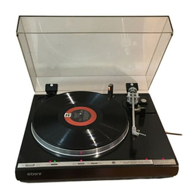
Sony HP-210 User manual


TABLE
OF.
CONTENTS
Title
Page
SERVICING
NOTES
ssi
visas
earnctialaenh
bata
alana
ater
MES
1
SECTION
1
TECHNICAL
DESCRIPTION
1-1.
Technical
Specification
..0.........2:cccccsceeeecseserececcseeersssencessecessesensees
2~3
122)..°
“Circuit?
Analysis)
csiscjocdsccesasactcs
eben
iakek
ccc
cdehcagee
sig
teinsdowesceseeuuesdveses
3~7
13:
“Block.
Diagram.
-scicccsicsceassecgccescsecunsd
caceth
dent
vqustndesaa
sates
etvssssedevssesucsess
wees
8
124;
“Teevel
Diagram:
«23.i.ssideiebidssccecich
eck
sdece
te
tewadentesenssevessvsscavecse?eieesesewsdveceas
9
SECTION
2.
DISASSEMBLY
AND
REPLACEMENT
PROCEDURES
2-1.
Tools:
Requited
9
scccsi.c.
cscs
ccsiecasieceschovsesivevseoventcceccescaceaseseees
10
2-2.
Hardware
Identification
Guide
;
10
2-3,
Top
Cover
Removal
.....ci.cccccccusscsenseccoccessenssonsocnessonctoceccecssesecscasaaees
11
2-4.
Record-Changer
Removal
.00.........ccccsessssseceeseececceceeceneeseneecees
aieeesetes
11
2-5.
Front
Panel
Removal
.........ccccccsecscsssrecccedsccssssccsssssssccssssonssssceensseses
12
2-6.
Wooden
Case
Removal
..........cscccssecseseseseeessesseeesseeesneesaseneneessneesenes
13
2-7.
Dial-Cord
Restringing
.0........scesseseesseesseeesseesneeeeesneennecsensenseee
2-8...
Mechanical
Dial
Calibration
.............cscsscssesscssecsssnsearsnseneiosenesotenees
2-9.
Pilot
Lamp
Replacement
sacedbesccen
seSesevss
dasnwoagenceeceesdegevassessaeserses
seseeeed
.
2-10...
Control
and
Swtich
Replacement
..........s200%
sSecreacbeeoos
QTL.
POR
RemiOval:
<scarssvsiaaspandetarinndertss
:
2-12.
Ac
Outlet
Replacement
.o..c.cccccesseeseeeeeeee
'2+13.
Power
Transistor
Replacement
—...........cc00.
Q-
14:
Chassis
LAV
OME:
ssccosticcussenceshevcsothenectouasiziopas
ee
SECTION:
3
"
ALIGNMENT
AND
ADJUSTMENT
PROCEDURES
3-
i
FM
I-f
and:
Discriminator
Alignment
.........
baatlenis
21
3-2...
FM
Frequency
‘Coverage
Alignment
2122
9,23
RB
FM
Tracking
Alignment.
;
re
ya,
BAS
A-m.
I:
‘Strip’
Mien
ciene.
o
on
25
~:26
3-5;
AST
‘Frequency.
Coverage
and
Tracking
Alignment.
26~
~.
28
ae
Power-Amplifier
Adjustments
‘
.
220
29
"RECORD.
CHANGER
‘SERVICING.
PROCEDURES
7
1,
*
Line‘Frequency
Change-...
ies
,
,Line-Voltage
Change.
wteee
30
:
Cartridge
Replacement
Stylus.
Tip
Replacement
aa
Diagram
-—
Power
ee
a
Power
Supply
Board
—
oiu..eeieccccsssscesssecssrsccsesessseceecsseens
36
~
37
6-4.
Mounting
Diagram
—
Preamplifier
Board
—
oesovensoseserssnsecsseneses
38
~
39
6-5.
Schematic
Diagram
—
Tuner
and
MPX
Section
—
.............
41
~
42
6-6.
Schematic
Diagram
—
Audio
Amplifier
Section
—
...........
43
~
44
SECTION
7
EXPLODED
VIEW
......000
je
desu
cotevcuudensesysbseBonhteckocssees
45
~
47
SECTION
8
ELECTRICAL
PARTS
LIST
.o.ccccccccccscsssoss
RCRA
CON
48
~
52

SERVICING
NOTES
__.1,_Be_certain
that
the
lead
wires
(blue)
for
the
dial lamp
are
affixed
to
the
front
subchassis
with
electrical
tape,
_
otherwise
hum
will
be
picked
up
at
the
preamplifier
stage.
See
Fig.
A.
Be
certain
that
the
discriminator
transformer
shield
is
reinstalled,
otherwise
hum
will
be
picked
up
from
the
record
changer
motor.
See
Fig.
B.
In
this
set,
“‘wire-wrap”
connections
are
employed
as
shown
in
Fig.
C.
In
case
a-wire
breaks,
simply
solder
the
lead
wire
directly
to
the
terminal
post.
Wire-wrap
connection
cannot
be
properly
made
by
hand.
Care
should
be
taken
not
to
cut
too
deep
when
removing
the
insulation
from
wire.
Even
the
slightest
nick
in
the
copper
wire
will
weaken
the
wire
enough
to
eventually
cause
a
break
at
that
point.
Use
a
soldering
iron
to
remove
the
insulation.
electrical
tape
Fig.
A
Affixing
lead
wire
shield
cover
terminal
post
Discriminator
--—
transformer
IFT201
Fig.
B
{FT201
and
shield
cover
.
Fig.
C
“Wire-wrap”
connection

SECTION
1
TECHNICAL
DESCRIPTION
1-1,
TECHNICAL
SPECIFICATIONS
Technical
specifications
for
the
HP-210
are
listed
in
Table
1-1.
TABLE
1-1.
HP-210
TECHNICAL
SPECIF
ICATIONS
Fm
Tuner
Section
Antenna:
Frequency
range:
Intermediate
frequency:
Usable
sensitivity:
Sigtaltecnpise
ratio:
Capture
ratio:
Selectivity:
Image
rejection:
I-f
rejection
Spurious
signal
rejection:
A-m
suppression:
Frequency
response:
Harmonic
distortion:
Fm-stereo
separation:
19-kHz,
38-kHz
suppression:
300
ohms
balanced
87.5
to
108
MHz
10.7
MHz
2.5uV
(S/N
=
30
dB)
1.6uV
(S/N
=
20
dB)
65
dB,
IHF
1.5
dB,
IHF
50
dB,
THF
45
dB
80
dB
49
dB
50
dB
50
to
15,000Hz
+2
dB
Mono:
0.5%
at
400Hz
Stereo:
0.8%
at
400
Hz
Greater
than
36
dB
at
400
Hz
45
dB
A-m
Tuner
Section
Frequency
range:
Intermediate
frequency:
Sensitivity:
Signal-to-noise
ratio:
$30
to
1,605
kHz
455
kHz
50
dB/m,
built-in
antenna
10zV,
external
antenna
50
dB
____
Image
rejection:
_
_
40
4B
at
600
kHz
I-f
rejection:
Harmonic
distortion:
35
dB
at
1,400
kHz
40
dB
at
1,000
kHz
0.8%
Audio
Amplifier
Section
Dynamic
power:
(IHF
constant
power
supply
method)
Music
power
output:
(EIA)
Continuous
RMS
power:
Harmonic
distortion:
Frequency
response:
Input
sensitivity
and
impedance:
Signal
output:
Signal-to-noise
tatio
(IHF
(B)
network):
Tone
controls:
.
Loudness:
28
watts,
both
channels
operating,
8
ohms,
1%
THD
36
watts
total
10
watts,
per
channel,
both
channels
operating,
8
ohms
Less
than
1.0%
at
1
kHz
at
rated
output
:
AUX:
(+3
dB)
TAPE:
|
30
to
50kHz
at
1-watt
output
PHONO:
600
mV,
1M
ohms
TAPE:
400mV,
100k
ohms
AUX:
250
mV,
100k
ohms
REC/PB:
400
mV,
100k
ohms
REC
OUT:
250
mV,
10k
ohms
x
REC/PB:
30mV,
80k
ohms
PHONO:
greater
than
58
dB
TAPE:
AUX:
greater
than
66
dB
BASS:
+10dB
at
100
Hz
TREBLE:
+10dB
at
10kHz
8
dB
up
at
50Hz
4dB
up
at
10kHz
(VOLUME-control
tion:
30
dB)
attenua-
%
:
General
Export
Model
only

~~Record
changer:
--"-~
Phonograph
Section
BSR
-C-116,
~four~-speeds—
(1673,
3331/3,
45,
78
rpm)
Cartridge:
SONY
Crystal
Cartridge
VX-18P
Stylus:
SONY
Diamond
Stylus
ND-120P
Number
of
records
played
automati-
cally:
Up
to
5
LP
records
Speaker
Section
(SS-210)
System:
2-way
(61/."
(16
cm)
woofer,
2”
(5
cm)
tweeter)
Impedance:
|
8
ohms
Dimensions:
91/,"
(width)
x
15”
(height)
x
83/3"
(depth)
235
mm
(width)
x
380
mm
(height)
x
213
mm
(depth)
Net
weight:
6lb
10
0z
(3.0
kg)
Shipping
weight:
18
Ib
120z
(8.5
kg)
per
pair
in
shipping
carton
General
50
watts
x
75
watts
120V
ac
x
100,
120,
220,
240V
50/9
Hz
ac
Power
consumption:
Power
requirements:
Dimensions:
x
161/g"
(depth)
421
mm
(width)
x
241
mm
(height)
x
410
mm
(depth)
241b
80z(11.1kg)
30lb
1402
(14kg)
Net
weight:
Shipping
weight:
%*
:
General
Export
Model
only
1-2.
CIRCUIT
ANALYSIS
The
following
describes
the
functions
of
all
stages
and
controls.
The
text
sequence
follows
signal
paths.
Stages
are
listed
by
transistor
reference
designation
at
the
left
margin;
major
components
are
also
listed
in
a
similar
manner.
Refer
to
the
block
diagram
on
page
7
and
the
schematic
diagrams
on
pages
40
to
43.
16%16"
(width)
x
91/2"
(height)
Stage/Control
“Fm
Front-End
~
Balun
Bi01
Rf
amplifier
Q101
Local
oscillator
Q103
AFC
circuit
D101,
D102
C115,
C119,
R113,
R114,
RIS
Function
This
transformer
matches
300-
ohm
twin
lead
to
the
fm
front-
end’s
input
stage.
The
rf
amplifier
and
tuned
cir-
cuits.
provide
high
sensitivity,
good
image
rejection,
and
good
selectivity.
Field-effect
transistor
Q101
is
ideally
suited
for
this
job
since
it
has
low-noise
charac-
teristics
and
a
wide
dynamic
range.
The
latter
characteristic
results
in
very
low-cross
modula-
tion
products.
Antenna
coil
L101
is
tapped
to
match
the
low-input
impedance
of
the
common
gate
amplifier.
This
oscillator
supplies
injection
voltage
to
the
mixer
via
oscil-
lator
coil
L103.
The
circuit
is
a
modified
Hartley
oscillator
with
feedback
applied
to
the
emitter
from
a
tap
on
tank
coil
L103.
An
automatic
frequency
control
circuit
is
incorporated
in
the
oscillator
to
provide
easy
recep-
tion
of
fm
signals.
Tuning
is
usually
performed
by
ear,
that
is,
turning
the
tuning
knob
and
setting
it
to
the
position
where
the
clearest
sound
is
heard.
How-
ever
this
is
rather
difficult
job.
By
using
afc,
the
difficulty
of
tuning
and
frequency
drift
in
the
local
oscillator
can
be
elimi-
nated.
The
principle
of
afc
operation
is
as
follows:
When
the
tuner
is
correctly
tuned,
the
intermediate
fre-
quency
is
kept
10.7
MHz
and
no
dc
correction
voltage
is
produced
by
the
ratio
detector
as
shown
in
the
‘“S”
curve
response
Fig.
1-1.
So,
the
voltage
applied
to
diode
D101
is
determined
solely
by
the
positive
fixed
-
reverse
bias
voltage
supplied
by
zener
diode
D102.
Now
assume
that
the
local
oscil-

Stage/Control
Mixer
Q102
Fm
I-f
Amplifier
I-f
amplifiers
Q201
to
Q204
I-f
output
Q205
Function
lator
frequency
changes
by
taf.
This
means
that
the
new
inter-
mediate
frequency
is
10.7
MHz
+af.
See
Fig.
1-1.
As
the
result
a
positive
dc
com-
ponent
is
fed
back
to
the
anode
of
D101,
decreasing
the
reverse
voltage
to
it,
and
making
D101’s
barrier
capacitance
increase.
This
decreases
the
local
oscillator’s
frequency
since
the
series
circuit
composed
of
C119
and
D101
is
connected
in
parallel
with
the
tank
circuit
of
the
local
oscil-
lator.
Conversely,
if
the
local
oscillator
frequency
decreases,
a
negative
dc
voltage
is
fed
back
to
D101,
increasing
the
local
oscil-
lator
frequency.
Rf
signals
and
local-oscillator
voltage
are
heterodyned
in
the
base-emitter
junction
of
mixer
Q102
to
produce
10.7-MHz
i-f
output
signal.
Transformer
IFT-
._
101
and
capacitors
C105
and
C106
form
a
high
“C’’,
pi-net-
work
bandpass
passes
the
i-f
output
and
pro-
vides
a
path
to
ground
through
~
C105
and
C106
for
the
other
heterodyne
products
and
oscil-
lator
harmonics.
The
i-f
amplifier
stages
consist
of
two
pairs
of
direct-coupled
amplifiers
that
provide
essen-
tially
flat
response.
The
selectivity
of
this
section
is
determined
by
two-pairs
of
filters
(CF201,
CF202,
CF203,
and
CF204)
in
the
inter-stage-
coupling
path.
Each
of
these
filters
is
a
two-section
ceramic
filter
that
operates
in
the
“trapped-energy”
mode.
The
filters
provide
extremely
sharp
skirt
selectivity
and
flat
response
inside
the
pass
band.
These
filters
determine
overall
selec-
tivity
in
the
fm
tuner.
Q205
provides
power
to
drive
the
ratio
detector.
filter,
which
©
Stage/Control
~
Ratio
detector
IFT201,
D201,
D202
MPX
Decoder
SCA
trap
coil
L301,
C306
19-kKHz
amplifier
Q303
Fig.
1-1
Function
IFT201:
and
diodes
D201
and
D202
form
a
balanced
ratio
de-
tector
that
transformes
the
fre-
quency-modulated
signal
into
an
audio
signal.
Output
appears
across
C207.
The
composite
signal
containing
monaural
information
from
0
to
15
kHz,
the
19
kHz
pilot
carrier
and
the
stereo
signal
at
38
kHz
+15
kHz
is
fed
to
the
MPX
de-
coder
through
a
trap
consisting
of
L301
and
C306.
This
trap
removes
the
-unwanted
SCA
signals
(67
kHz)
to
feed
a
clean
composite
signal
to
the
base
of
Q303.
This
stage
serves
two
functions.
It
extracts
the
19-kHz
pilot
signal
by
means
of
a
tuned
circuit
at
its
collector,
and
pro-
vides
a
low-impedance
source
of
composite
stereo
signal
(without
_the
pilot
carrier)
at
its
emitter.
Series-resonant
circuit
in
the
emitter
circuit
eliminates
the
19-kHz
pilot
signal
from
the
composite
stereo
signal.
local
oscillator
freq.
10.7
MHz
RF
signal
“S”
curve
response
%
Af:
frequency
drift
Lacal
oscillator
frequency
drift
and
-
afc
voltage
relation

7
all
Stage/Control
“Frequency”
doubler
D301,
D302
38-kHz
amplifier
Q305
STEREO-lamp
circuit
Q304,
Q305
Multiplex
demodulator
D303,
D304
D305,
D306
Function
Signals
developed
at
the
collec=
tor
of
Q303
are
transformer-
coupled
to
a
full-wave
rectifier
consisting
of
D301
and
D302.
The
output
of
this
rectifier
is
not
filtered,
resulting
in
two
positive
pulses’
for
each
input
cycle.
Thus
the
19-kHz
pilot-
carrier
frequency
is
effectively
doubled
by
D301
and
D302.
However,
the
waveform
is
not
sinusoidal
at
the
base
of
Q305.
The
38-kHz
pulses
produced
by
D301
and
D302
are
amplified
by
Q305.
The
tank
circuit
at
the
collector
of
Q305
is
tuned
to
38
kHz
to
restore
these
pulses
to
a
sinusoidal
waveform
for
use
as
a
switching
signal.
This
signal
is
transformer-coupled
to
the
bridge-type
demodulator
to
supply
sampling
drive
for
the
demodulator:
The
STEREO
indicator
lights
when
an
fm-stereo
signal
is
received.
The
emitter
of
Q305
is
connected
to
the
base
of
Q304,
which
is
normally
cut
off.
The
circuit
operates
as
follows:
When
a
composite
stereo
signal
is
applied
to
the
multiplex
de-
coder,
the
38-kHz
pulses
pro-
duced
at
the
output
of
the
frequency
doubler
yield
a
higher-
average
current
flow
through
Q305.
This
forces
Q304
into
conduction,
lighting
STEREO
indicator
lamp
PL1.
The
demodulator
circuit
em-
ploys
four
diodes
in
a
balanced
bridge
arrangement.
This
system
has
the
advantage
of
cancelling
residual
rf
components
(38-kHz
signal,
some
19-kHz
signal,
and
higher-order
harmonics
of
these
frequencies).
“L”
and
““R”
com-
ponents
are
developed
at
each
side
of
the
bridge
as
the
result
of
demodulation,
when
the
receiver
is
operated
in
the
stereo
mode.
In
the
monaural
mode,
diodes
D303
and
D304
are
Stage/Control
De-emphasis
circuit
C319,
C320
Twin-T
filter
C321,
C325,
R335,
R332,
R336,
C324
(C322,
C326
R334,
R333,
R337,
C323)
A-m
Tuner
Local
oscillator
Q404
Mixer
Q401
I-f
amplifier
Q402
Ceramic
filter
CF401
Function
forward
biased
by
supply
volt-~
age
through
the
STEREO
lamp,
R321,
R326
and
R327,
so
these
diodes
merely
act
as
small
resist-
ances.
Under
this
condition,
the
monaural
signal
is
applied
to
both
“L”
and
“R”
audio
ampli-
fiers.
These
capacitors
provide
the
roll-off
at
high
audio
frequencies
necessary
to
compensate
for
pre-
emphasis
at
the
transmitter.
This
filter
eliminates
the
38-kHz
carrier,
thereby
preventing
carrier
leak.
This
stage
supplies
injection
volt-
age
to
the
mixer
via
L402.
The
circuit
is
a
modified
Hartley
oscillator
with
feedback
applied
to
the
emitter
of
Q404
from
the
tap
on
the
secondary
winding
of
oscillator
coil
L402.
Incoming
rf
signals
and
!ocal-
oscillator
voltage
are
hetero-
dyned
in
the
base-emitter
junction
of
Q401
to
produce
the
455-kHz
output.
IFT401
is
a
transformer
tuned
for
455
kHz.
It
develops
the
i-f
signal,
and
provides
a
path
to
ground
through
bypass
capacitor
C405
for
the
other
heterodyne
products.
The
low-impedance
output
winding
of
IFT401
pro-
vides
link
coupling
to
if
amplifier
Q402.
This
stage
is
basically
an
RC-
coupled
amplifier.
The
selec-
tivity
of
the
stage
is
determined
by
a
double
ceramic
filter
(CF401)
in
the
interstage-coupl-
ing
path.
This
filter
provides
extremely
sharp
skirt
selectivity
inside
the
pass
band.

Stage/Control
L-f
amplifier
Q403
Age
circuit
D402,
R415,
C426,
R428,
C425,
R412,
R427,
C422,
C421,
R401
Audio
Amplifier
Function
‘This
circuit
provides
the
power
to
drive
envelope
detector
D401.
The
positive
de
component
at
the
cathode
of
diode
D402
is
fed
back
to
the
base
of
Q403,
and
from
there
to
Q401
to
control
its
gain.
The
time
constants
of
the
age
components
filter
audio
variations
out
of
the
agc
voltage.
Since
the
audio-amplifier
section
contains
two
identical
amplifier
chains,
only
the
left
channel
will
be
described.
MODE
switch
82
Preamplifier
Q501,
Q502
Equalization
circuit
R505, C502,
R506, C501,
R503
Feedback
circuit
‘R519,
C510
Attenuator
|
R501,
R502,
R507,
R508
In
the
STEREO
position
of
S2,
left
and
right
input
signals
are
routed
to
their
respective
ampli-
fiers.
In
the
MONO
position,
the
left
and
right
signals
are
added.
The
sum
is
then
fed
to
both
amplifier
channels.
This
stage
amplifies
the
small
signal
provided
by
the
phono
cartridge,
tape
recorder,
to
the
level
required
at
the
input
of
the
power-amplifier
section.
The
preamplifier
uses
a
complicated
negative-feedback
technique
that
provides
stable
operation
during
temperature
changes,
and
good
amplification
at
low-frequencies.
It
also
applies
the
audio
signal
to
the
REC
OUT
jack
for
optimum
recording.
Phono
equalization
is
achieved
by
these
filter
circuits
to
obtain
a
flat
response.
In
the
any
position
of
the
FUNCTION
|
switch,
feedback
is
applied
through
R519
and
C510
to
provide
a
flat
response
in
the
preamplifier.
Be
sure
to
use
replacement
components
with
the
exact
same
values.
Signal
applied
to
the
TAPE
or
AUX
input
jack
is
attenuated
by
these
resistors.
This
allows
the
HP-210
to
accept
signals
of
Stage/Control
Channel
separation
adj.
R524
BASS
control
RV531
TREBLE
control
RV532
Loudness
circuit
R536,
R537,
C535,
C536
VOLUME
CONTROL
RV701
Predriver
Q503
Ac
balance
adj.
RV541
Phase
inverter
Q504
Function
about
400
mV
at
the
TAPE
and
250mV
at
AUX
input
jack,
and
amplify
them
without
distortion.
This
network
connects
the
emit-
ters
of
preamplifiers
Q501
and
Q601
only
when
the
FUNC-
TION
switch
is
set
to
the
FM
position.
It
provides
a
form
of
negative
feedback
between
the
left
and
right
channels.
Any
residual
inverted
“L”
signals
in
the
“‘R”
channel
are
cancelled
out
by
the
“L”
signal
from
the
“L”
channel.
The
same
is
true
of
residual
“R”
signals
in
the
“L”
channel.
This
control
has
a
range
of
+10dB
at
100Hz.
i
This
control
has
a
range
of
£10dB
at
10kHz.
This
compensates
for
the
charac-
teristics
of
the
human
ear,
whose
tonal
response
varies
according
to
the
loudness
of
the
sound
being
heard.
High-
and
low-
frequency
components
are
in-
creased
in
‘inverse
proportion
to
the
VOLUME
control
setting
by
means
of
R536,
R537,
C535
and
C536.
The
level
of
signal
applied
to
the
power
amplifier
is
deter-
mined
by
the
setting
of
RV701.
Q503
amplifies
the
signal
to
the
level
required
at
the
power
output
stages.
Controls
the
bias
current
of
Q503
and
Q504
to
the
point
where
positive
and
negative
half
cycles
are
simultaneously
clipped
when
increasing
the
input
signal.
It
also
affects
the
rated
output
power.
Stage
Q504
has
two
oppositely-
phased
outputs
to
drive
the
-
power-output
stages
in
push
pull.

Stage/Control
Positive
bias
power
supply
D501,
D502,
D503
De
bias
adj.
RV542
Negative-
feedback
loop
R557,
R556
C547
Drivers
Q505,
Q506
Power
amplifier
Q507,
Q508
Function
These
diodes
are
forward
biased
by
supply
voltage
through
R564
and
provides
stabilized
dc
volt-
age
of
about
1.8V,
supplying
idling
current
for
Q506,
Q606.
Controls
the
idling
current
in
Q505,
Q506,
Q507
and
Q508
to
eliminate
crossover
distortion
at
small
signal
levels.
These
components
provide
nega-
tive-feedback
voltage
from
the
output
of
the
power
amplifier
to
the
emitter
of
Q503.
These
transistors
operate
as
emitter
followers
to
provide
the
current
swings
demanded
of
the
output
stages
for
full
output.
These
SONY
silicon
transistors
have
been
specially
manu-
factured
to
drive
the
speaker
system.
Output
is
coupled
to
the
speakers
through
C548.
Stage/Control
Power
Supply
—
Voltage
regulator
Q509,
Q510
Function
DC
output
from
rectifier
D504,
D505
is
filtered
by
C701
and
applied
to
series
regulator
Q510.
Q509
compares
a
sample
of
the
output
voltage
picked
off
across
R568.
A
change
in
output
voltage
is
detected
at
the
base
of
Q509
and
there-
fore
alters
its
collector
voltage.
Since
the
collector
of
Q509
is
directly
coupled
to
the
base
of
Q510,
the
change
in
output
voltage
alters
the
conduction
of
Q510
by
the
amount
neces-
sary
to
maintain
the
output
voltage
constant.
An
increase
in
output
voltage
causes
an
increase
in
the
impedance
(de-
crease
in
conduction)
of
Q510,
and
vice-versa.
The
dc
output
voltage
supplied
to
the
tuner
is
thus
stable.

BLOCK
_DIAGRAM____
1:3.
|
HOY
No
yaNvdds
Our
FNOHIAV3H
HITEC
YINVIdS
|
-
goga
‘vosa
Ss
YHSILIIY
«
2
SAVM
TINd
S.
=al
Soest
o
fr----
=
4NOLLIaS
XaW
pue
iount
01
Go
x
1
df
XOld
|
{
a
j
TVLSAHD
=
!
|
{
oC!
|
|
i=
!
|
oo
1
i]
i
i]
1
i]
2
base
sco
|
5
OLED
Ysa
|
Ee
peaee
a
[—
2
I
_
1
=
E
I
=
I
°
.
3
|
z0za
‘joza
|
3
|
.
HOLIILIG
|
<x
|
-
Oey
I
L
8050
°
FHUATING
Y3MOd
LNo
£050:
|
YA
TNVY
YIWYOF
“SNVEL
‘43MOd
|
2osa
“tosa
-8IMOd
IOV
|
$0z0
“v0z0.
|
020
Y3dI7.,
dW
PWS
IVEGIIA
IG
‘IV
9050
YIAlYa
2050
|
AlddNS
LTOA
SVIE
0ts0
‘600
|
¥OLYINDIY
FOVLIOA
1S.‘MS
NOLLDNNS
OL
OF
#050
YIAIOTUd
|
(HO-¥)
|
YLT
-
wn.
NIML,
|
(H2-7)
|
YILVFZ
ads
NIML
0249
“c0z49
|
;
Y2ltis
IINVYID
£050
eRdTdWe
2
aad
r-~-~--
2020
‘10z0
|
Bald
TW
TS
(H9-7
se
awes)
OFANIGNY
HI"
0v0
=
[
|
{
t
1
i
\
seo
TI
We)
xn
|
\
|
i
1
|
I
i
1
©
no
234
;
‘
|
(Hou)
1no|xaw
on
@
|}
1
6)
3d
Se
ni
erert
Ae
i
J
lus
saow
9
NOL
4°
'G
i
!
|
"038348
|onow
0
©
ONOHs
|
|
1
\
ic
|
|
-
g
;
J
(F78FUL
200.
‘Logo
7
t
Brainy
SSV8)
1O¥L
|
Yad
TAN
©
xnv
\
il
“NOD
FNOL
“Sud
'
:
|
(HO-1)
4NO
Xaw
oL
@
©
ino
934
'
|
os
eet
See
Se
A
ee
eal
“ave
gee
a
su
NOILIIS
UFIJITINY
OLGNY
{
i
eet
eet
tl
ee
ee
ee
q---
I
I
29”
Z0Eq
‘1oEa
|
|
_¥37EN0G
AONINOIS
YFIFITIWY
4
7H
SE
y
zoio
|
|
WIXIN
WA
es
a a
a
ee
ea
a
ne
ae
ee
ee
ee
|
oov
:
£00
|
YSISITAWY
ZHYEL
|
d
1010
|
USS
TANY
|
a
WW,
YOLYI1I9SO
wy
|
r
7
VNNILNY
£060
1o¢4
Zov0
|
WY
YS
TING
wILd
YRSITAWY
awe
OINWYIO
aA
ii
YNNZLNY
WI.
NOLLOIS
XdW
ONY
HYINNL

1-4.
LEVEL
DIAGRAM
(Ajuo
jappoyy
ysodxy
jesauay)
YOLIAFNNOD
ad/27d
|
7o¥LNO9
|
WNTOA
JOYLNOD
ovr
|
INOL
INOHdIVIH
———
TOYLNOD
TOYLNOD
[TO
SSV@
F71974L
YyFsITdNVIdd
~~
NOLLINNZ
aOR
ae
teks
erred
EET
ERE
ET
OUE
MT
_j
4ORIaS
49UNI
OL
_BFIST
TAN
4IMOd
(Aw
924)
———_y
aP
1
'S¢-
y
7
(Awg1)
ap
ge-
|?
7
|
YINNL
7
;
7
(1)
oe-
(Au
gz)
:
¢
GP
Ze-
ie
7
(Awoge)
gP
OL~
ss
ot-
7
7
<
Oo
ap
4
wes
ef
(AW00b)
AP
S-
3dV-4
wamuoos
ot
abet.
(AW0SS)
ap
€-
ONOHd
+
Bet
a
O&+
‘ZHAT
SASLL'O
0%
portasox
gp
ul
possordxe
pue
WALA
U}IM
pornseour
or
o8e}[0A
[eUsTg
:eI0N

2-5.
FRONT
PANEL
REMOVAL
Remove
the
top
cover
as
described
in
Procedure
2-3.
Remove
the
all
control
knobs
by
pulling
them
off.
”
Remove
the
HEADPHONE
jack
by
using
jack
driver
or
pliers.
Refer
to
cross
sectional
view
Fig.
2-4,
lift
the
bottom
part
of
the
front
panel
up
while
pulling
it
forward
as
shown
in
Fig.
2-5.
This
frees
the
lower
catch.
Press
the
top
of
the
front
panel
as
shown
in
Fig.
2-6.
This
frees
the
front
panel.
To
reassemble
the
front
panel,
reverse
the
foregoing
procedures.
ee
Fig.
2-5.
upper
:
Fig.
2-6.
Front
panel
removal
(1)
Fig..2-4.
Cross
sectional
view
of
front
panel
Front
panel
removal
(2)
=
125=>
lower
catch

2-6.
WOODEN
CASE
REMOVAL
1.
Remove
the
record
changer
as
described
in
Procedure
2-4.
Remove
the
two
self-tapping
screws
(®
B
3x6)
securing
the
motor
board
bracket
to
the
front
subchassis
as
shown
in
Fig.
2-8.
Remove
the
six
self-tapping
screws
(®
B
3x6)
from
the
bottom
and
one
self-tapping
screw
(®
B
3x16)
from
the
rear
of
the
wooden
case
ie
as
shown
in
Fig.
2-7.
Carefully
lift
the
wooden
case
straight
up.
self-tapp
®B
3x16
self-tapping
|:
Screws
®
B
3x6
2-7.
DIAL-CORD
RESTRINGING
Preparation
1.
Remove
the
front
panel
and
wooden
case
as
described
in
Procedures
2-5
and
2-6.
2.
Cut
a
71-inch
(1800mm)
length
of
1/64-inch
(0.5
mm)
diameter
dial
cord.
3.
Tie
the
end
of
the
cord
to
a
spring
as
shown
in
Fig.
2-9.
4.
Rotate
the
tuning-capacitor
drive
drum
fully
counterclockwise
(minimum
capacitance
posi-
tion).
;
Fig.
2-9.
Tying
square
knot
in
the
coil
spring
Fig.
.2-8.
_Woodeén
case
removal

----Procedure-----
While
referring
to
Fig.
2-10,
proceed
as
follows:
Hook
the
spring
to
one
hole
of
the
drive
drum
as
shown
in
Fig.
2-11,
and
then
squeeze
it.
Run
the
cord
through
the
slot
in
the
rim
of
the
drum
and
wrap
a
counterclockwise
turn
in
the
inner
side
groove.
See
Fig.
2-12.
Run
the
cord
over
pulley
“A”,
and
then
wrap
three
counterclockwise
turns
around
the
tuning
shaft.
Run
the
cord
over
pulleys
“B’’,
“‘C”
and
“D”
then
wrap
three
counterclockwise
turns
around
Fig.
2-11.
-
Coil
spring
installation
pulley
“C”
@
aD
pulley
“B”
the
drum
from
outer
groove
to
inner
groove
as
shown
in
Fig.
2-12.
Pass
the
doubled
end
of
the
cord
through
the
eyelet
(See
Fig.
2-13),
then
hook
it
to
the
spring
as
shown
in
Fig.
2-14.
Tighten
the
cord,
then
squeeze
the
eyelet
so
that
the
spring
is
under
tension.
Make
a
knot
in
the
cord
end
to
keep
it
from
slipping
out
of
the
eyelet.
See
Fig.
2-13.
After
completing
the
dial-cord
stringing,
make
sure
that
the
tuning
system
works
properly.
Apply
a
drop
of
contact
cement
to
the
knots.
Perform
the
mechanical
dial
calibration.
Fig.
2-12.
Wrapping
the
dial
cord
pulley
“A”
tuning
shaft
(three
counterclockwise
turns)
Fig.
2-10.
Dial
cord
stringing
—
14
—

2-8.
Fig.
2-14.
End
of
dial
cord
stringing
MECHANICAL
DIAL
CALIBRATION
Note:
This
is
required
after
replacing
the
dial
cord.
Put
the
dial
pointer
on
the
cord
as
shown
in
Fig.
2-15,
and
move
it
to
a
position
where
the
pointer
coincides
with
the
guide
hole
provided
in
the
front
subchassis
as
shown
in
Fig.
2-16,
when
the
tuning
capacitor
is
set
to
the
maximum
capacitance
position.
Hook
the
dial
pointer
on
the
dial
pointer
restricting
cord
as
shown
in
Fig.
2-16.
Fig.
2-15.
Dial
pointer
installation
dial
pointer
=e
dial
pointer
restricting
cord
Fig.
2-16.
Mechanical
dial
calibration

2-9.
PILOT
LAMP
REPLACEMENT
Prepare
for
replacing
any
of
the
pilot
lamps
by
removing
the
record
changer
as
described
in
Procedure
2-4.
Stereo
Lamp
1.
Pull
the
lamp
from
its
rubber
holder.
2.
Unsolder
the
defective
lamp
leads
from
the
connecting
terminals
on
the
tuner
board,
and
then
install
the
new
lamp.
Dial
Lamp
1.
Remove
the
front
panel
as
described
in
Procedure
2-5.
2.
Pry
out
the
defective
lamp,
and
then
install
the
new
one.
2-10.
CONTROL
AND
SWITCH
REPLACEMENT
Prepare
for
replacing
any
of
the
controls
or
switches
by
removing
the
front
panel
as
described
in
Procedure
2-5.
:
TONE
Controls
1.
Remove
the
hex
nuts
that
secure
the
BASS
and
TREBLE
controls
to
the
front
subchassis
as
shown
in
Fig.
2-17.
Cut
the
two
lead
wires
connecting
between
the
tone
control
board
and
preamplifier
board.
Carefully
remove
them
along
with
the
tone
control
circuit
board.
Cut
each
lug
of
the
defective
control
on
the
board
to
remove
the
part.
VOLUME
control
SPEAKER
Sw
HEADPHONE
SW
jack
Fig.
2-17.
control
5.
6.
Unsolder
and
remove
the
clipped
lugs,
and
clean
out
the
holes
in
the
circuit
board.
Install
the
replacement
control.
FUNCTION
Switch
(slide/rotary
switch)
1,
TREBLE
control
GS
Remove
the
hex
nut
sécuring
it
to
the
front
subchassis
as
shown
in
Fig.
2-17.
Cut
the
two
lead
wires
connecting
between
preamplifier
board
and
tone
control
board
as
shown
in
Fig.
2-18.
Remove
the
lead
wires
from
the
clamp/PCB
support
one
by
one
and
then
unhook
the
fiber
support
as
shown
in
Fig.
2-18.
This
frees
the
preamplifier
board.
With
a
soldering
iron
having
a
solder-sucking
tip,
clean
the
solder
from
each
lug
of
the
defective
switch
and
the
printed
board.
Install
the
replacement
switch.
Fig.
2-18.
Preamplifier
board
removal
self-tapping
screw
@®B
3x6
FUNCTION
Sw
Control
and
switch
replacement

VOLUME
Control,
SPEAKER
Switch
and
HEADPHONE
Jack
1.
Remove
the
hex
nuts
that
secure
them
to
the
front
subchassis
as
shown
in
Fig.
2-17.
2.
Unsolder
the
lead
wires
from
the
defective
parts,
and
then
install
the
replacement
parts.
MODE
and
POWER
Switches
1.
Remove
the
two
screws
securing
the
switch
to
the
front
subchassis
as
shown
in
Fig.
2-17.
2.
Unsolder
the
lead
wires
from
the
defective
switch,
and
then
install
the
replacement
switch,
2-11.
PCB
REMOVAL
Prepare
for
removing
any
of
the
printed
circuit
boards
by
removing
wooden
case
as
described
in
Procedure
2-6.
Tone
Control
and
Preamplifier
Boards
1.
Refer
to
the
tone
control
replacement
pro-
-
cedures
for
tone-control
board
removal
as
described
in
Procedure
2-10.
2.
Refer
to
the
function
switch
replacement
pro-
cedures
for
preamplifier
board
removal
as-
described
in
Procedure
2-10.
See
Fig.
2-18.
Tuner
and
MPX
Board
1.
Fasten
the
dial
cord
to
the
drum,
pulley
“A”
pulley
“D”
pulley
“A”
vie.
s)
A
Remove
two
lead
wires
(red
and
orange)
from
‘|
this
clamp.
Power
amp
board
removal
Crt
MPX
board
and
pulley
‘“D”
‘with
cellophane
tape.
This
helps
you
to
restring
the
dial
cord.
2.
Unsolder
the
fm
and
a-m
antennal
lead
wires
from
the
antenna
terminals.
3.
Remove
the
three
self-tapping
screws
(®
B
3x6)
securing
the
tuning
capacitor
and
PCB
brackets
to
the
chassis
as
shown
in
Fig.
2-19.
This
frees
the
tuner
and
MPX
board.
Power
Amplifier
Board
1.
Remove
the
two
lead
wires
(green
and
black)
from
the
power
amplifier
PCB
support
and
the
two
lead
wires
(red
and
orange)
from
the
tuner
and
MPX
PCB
support,
and
then
remove
the
two
self-tapping
screws
securing
the
heat
sink
to
the
chassis
as
shown
in
Fig.
2-19.
This
-
frees
the
power
amp
PCB.
2.
Insert
the
tabs
of
the
PCB
into
the
opening
in
the
chassis
as
shown
in
Fig.
2-20.
This
helps
in
replacing
ot
checking
the
com-
ponents
mounted
on
PCB.
2-12.
AC
OUTLET
REPLACEMENT
|
1.
Remove
the
wooden
case
as
described
in
Procedure
2-6.
2.
Pry
out
the
socket
retaining
clip
with
a
screw-
driver
as
shown
in
Fig.
2-21.
This
frees
the
ac
outlet.
3.
Install
the
replacement
ac
outlet.
Remove
two
lead
wires
(black
and
green)
from
this
clamp.
Power
amp
board
remova
said
:
~
Fig.
2-19.
PCB
removal
oF

|________2-13..
POWER
TRANSISTOR
REPLACEMENT
Fig.
2-20.
Power
amplifier
board
removal
screw
Oriver
ac
outlet
Fig.
2-21.
Replacing
the
ac
outlet
2-14.
CHASSIS
LAYOUT
tuner
and
MPX
board
preamplifier
board
TONE
control
board
1.
2.
REC/PB
connector
{General
Export
Model
only.
1s
Remove
the
power
amplifier
board
as
described
in
Procedure
2-11.
Remove
the
two
screws
and
retaining.
bracket
securing
the
defective
power
transistor
to
the
heat
sink
and
PCB.
Unsolder
the
leads
of
power
transistor,
and
then
install
the
new
one.
When
replacing
the
power
transistor,
apply
a
coating
of
a
heat-transferring
grease
to
both
sides
of
the
insulating
mica
washer.
Any
excess
grease
squeezed
out
when
the
mounting
bolts
are
tightened
should
be
wiped
off
with
a
clean
cloth.
This
prevents
it
from
accumu-
lating
conductive
dust
particles
that
might
eventually
cause
a
short.
~—=—————
amplok
fuse
1.6A
_C701
1,000
pF
voltage
selector
(General
Export
Model
only,

|
SECTION
3
ALIGNMENT
AND
ADJUSTMENT
PROCEDURES
3-1.
FM
I-F
AND
DISCRIMINATOR
ALIGNMENT
CAUTION
The
ceramic
filters
in
the
fm
i-f
circuit
are
selected
according
to
their
specified
center
frequencies
and
color
coded
as
shown
in
Fig.
3-1
and
listed
in
Table
3-1.
Check
the
color
code
of
the
filters
to
identify
the
same
center
frequency
when
replacing
any
of
these
filters.
TABLE
3-1.
FM
LF
CERAMIC
FILTERS
Part
No.
Color
Specified
Center
Freq.
1-403-562-11
red
10.70
MHz
1-403-562-21
black
10.66
MHz
1-403-562-31
white
10.74
MHz
1-403-562-41
green
10.62
MHz
1-403-562-5
1
yellow
10.78
MHz
color
spot
Fig.
3-1.
Color
dot
on
ceramic
filter
|
“setts
WN
Interruption
of
fm
or
a-m
local
oscillator
operation
Fig.
3-2.
a
{9
—
Note:
Two
methods
of
i-f
discriminator
align-
ment
are
available,
sweep
generator
alignment
and
signal
generator
align-
ment.
You
can
use
either
of
them.
In
either
case,
the
local
oscillator
should
be
killed.
To
stop
the
local
oscillator’s
operation,
remove
the
shield
cover
over
the
local
oscillator
capacitor,
if
néces-
sary,
and
then:
shunt
the
oscillator
capacitor
with
a
0.02uF
capacitor.
See
Fig.
3-2.
:
Sweep
Generator
Alignment
Test
Equipment
Required
1.
.10.7
MHz
sweep
generator
2.
©
Oscilloscope
3.
Ceramic
capacitor,
0.02uF
4.
Alignment
tools
Preparation
1.
Remove
the
record
changer
as
described
in
Procedure
2-4.
2.
Connect
the
input
cable
of
the
oscilloscope
with
alligator
clips
to
R221
and
ground
on
the
fm
a-m
tuner
circuit
board,
and
solder
a
0.024F
capacitor
across
these
clips,
as
shown
in
Fig.
3-3.
3.
Connect
the
output
cable
of
the
sweep
gener-
Fig.
3-3.
ator
across
CV102
on
tuner
and
MPX
board.
Use
alligator
clips
and
make
the
connection
through
a
0.02zF
coupling
capacitor
as
shown
in
Fig.
3-4.
é
Fm
discriminator
output
connection

ay
—Procedure-——--—
ie
aes
SS
meres
~
1.
With
the
equipment
connected
as
shown
in
Fig.
3-5,
set
the
sweep
generator’s
controls
as
:
follows:
To
sweep
or
rf
generator
;
: :
Center
frequency.........
Specified
frequency
of
ceramic
filter.
See
Table
3-1.
Sweep
width
.......0000...
1
MHz
2.
Set
the
receiver’s
controls
as
follows:
FUNCTION
switch
.....
FM
AUTO
STEREO
VOLUME
control
......
Minimum
3.
Adjust
the
oscilloscope
controls
to
provide
a
visible
indication.
Note:
Two
or
three
traces
will
be
observed
on
the
oscilloscope
as
the
center
frequency
of
the
sweep
generator
varies.
The
trace
you
are
looking
for
has
the
largest
amplitude.
Once
you
get
it,
decrease
the
sweep
generator
output
low
enough
to
obtain
rather
noisy
output.
4.
Turn
the
top
core
(secondary
side)
of
discrimi-
nator
transformer
IFT201
with
an
alignment
tool
to
obtain
the
“S”
curve
response,
and
equalize
the
positive
and
negative
peaks
of
the
“‘S”
curve
response,
as
shown
in
Fig.
3-6.
Fig.
3-6.
“S”
curve
response
5.
Adjust
i-f
transformer
IFT101
(see
Fig.
3-11)
and
primary
side
of
discriminator
transformer
(IFT201
bottom
core)
to
obtain
a
maximum-
amplitude
“‘S’’
curve
response.
.
oscilloscope
HP-210
————
902m
EN
aur
|
10.7
MHz
ae
sweep
|
evro2
R221
V H
|
generator.
o
O°
i
o
ee
ee
Fig.
3-5.
Test
setup
for
discriminator
alignment
by
sweep
generator
Table of contents
Other Sony Turntable manuals

Sony
Sony AIVA AZ-BS1 User manual

Sony
Sony PS-LX250H User manual

Sony
Sony DD-57 User manual

Sony
Sony NW-A45 User manual

Sony
Sony PS-HX500 User manual

Sony
Sony PS-X60 User manual

Sony
Sony PMW-PZ1 User manual

Sony
Sony CDX-C800 User manual

Sony
Sony NW-A45 User manual

Sony
Sony PS-FL7II - Stereo Turntable User manual

Sony
Sony Hi-MD Walkman MZ-RH10 User manual

Sony
Sony PS-LX2C User manual

Sony
Sony PS-LX55 User manual

Sony
Sony NW-A25 User manual

Sony
Sony D-F181 - Fm/am Portable Cd Player User manual

Sony
Sony Walkman WM-FX900 User manual

Sony
Sony PS-X55 User manual

Sony
Sony PS-J10 Primary User manual

Sony
Sony PS-X6 User manual

Sony
Sony MDX-F5800 User manual