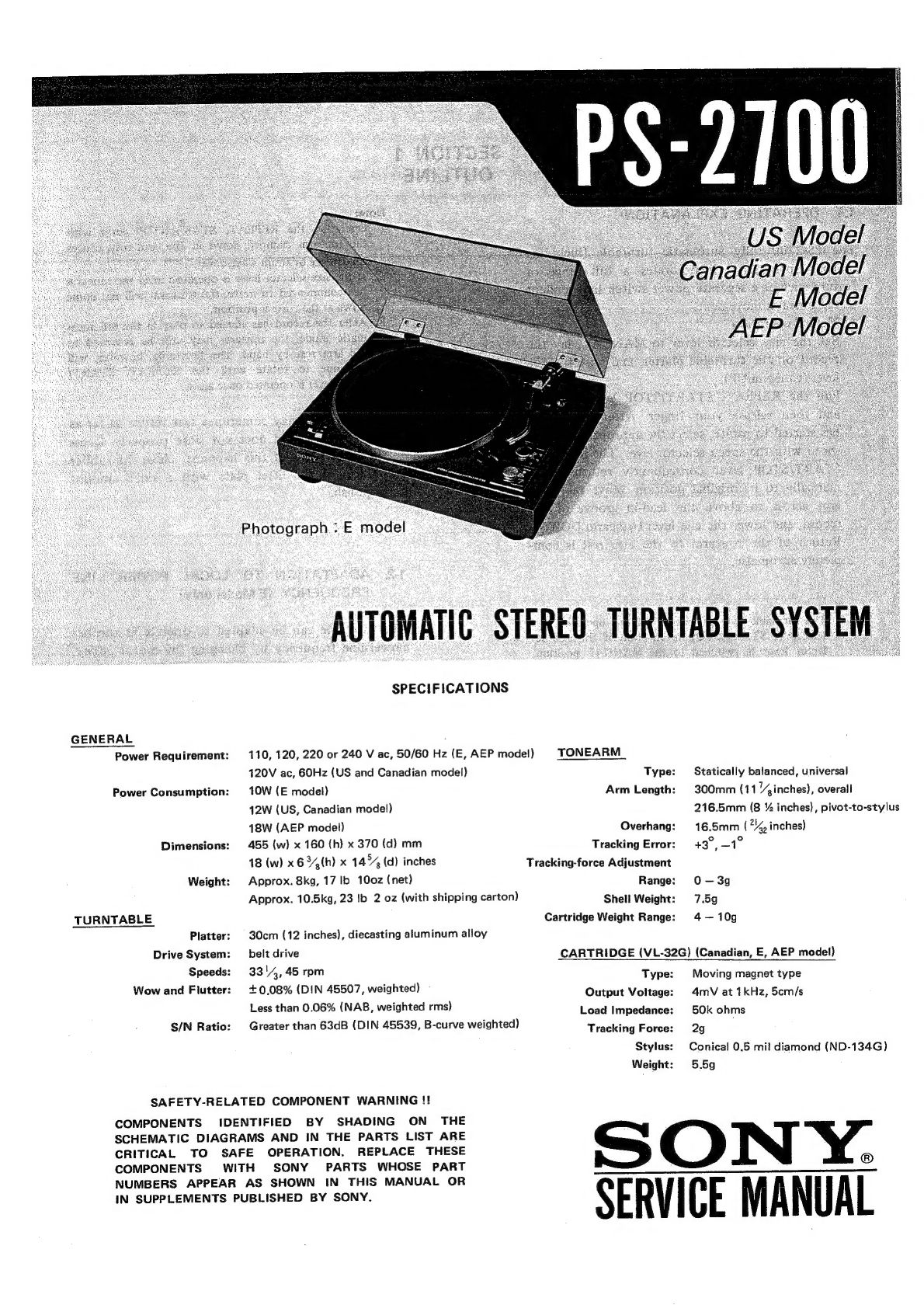
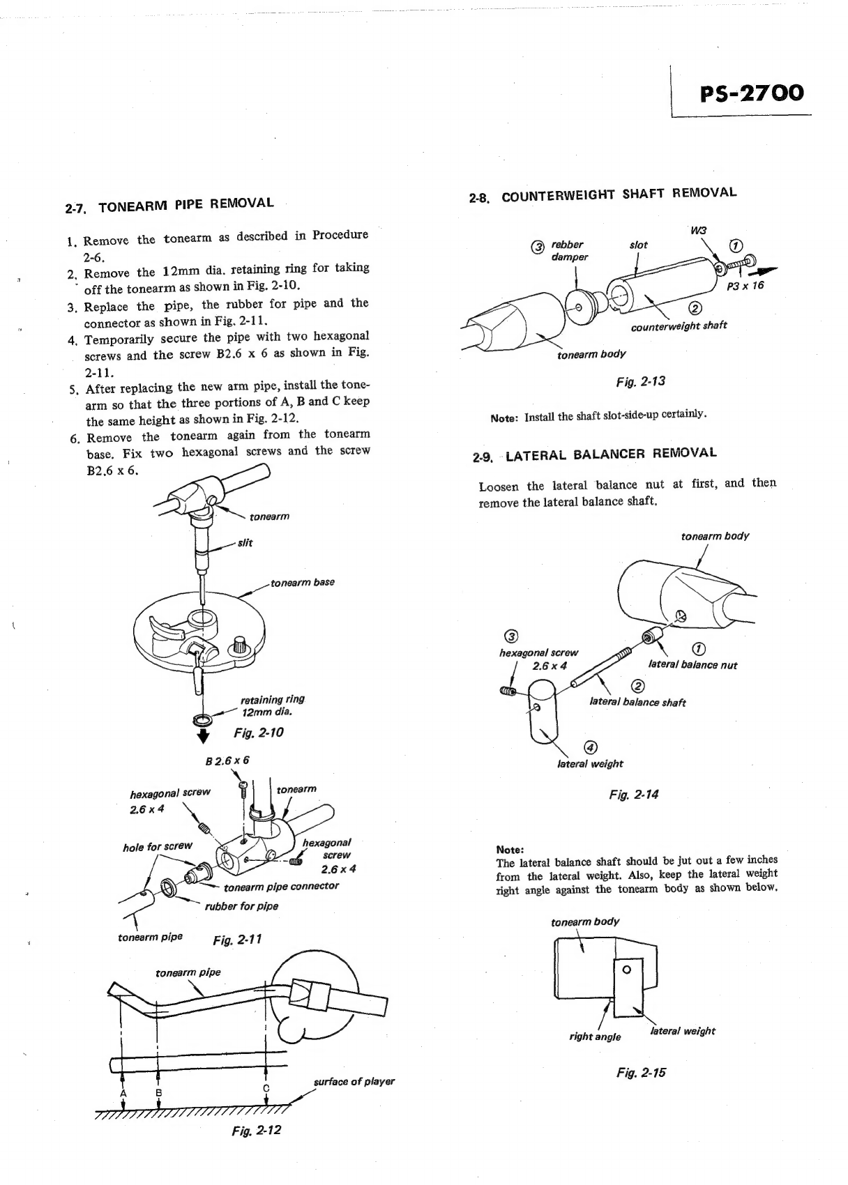
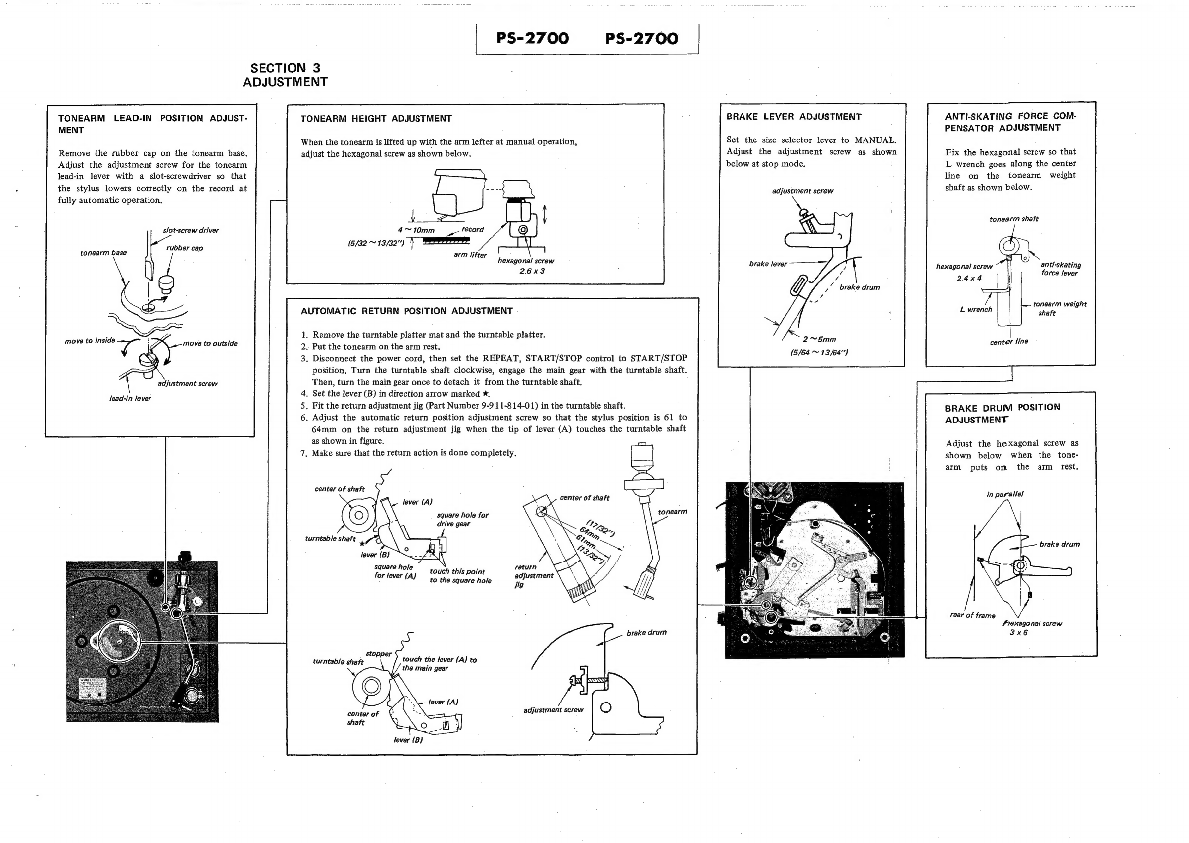
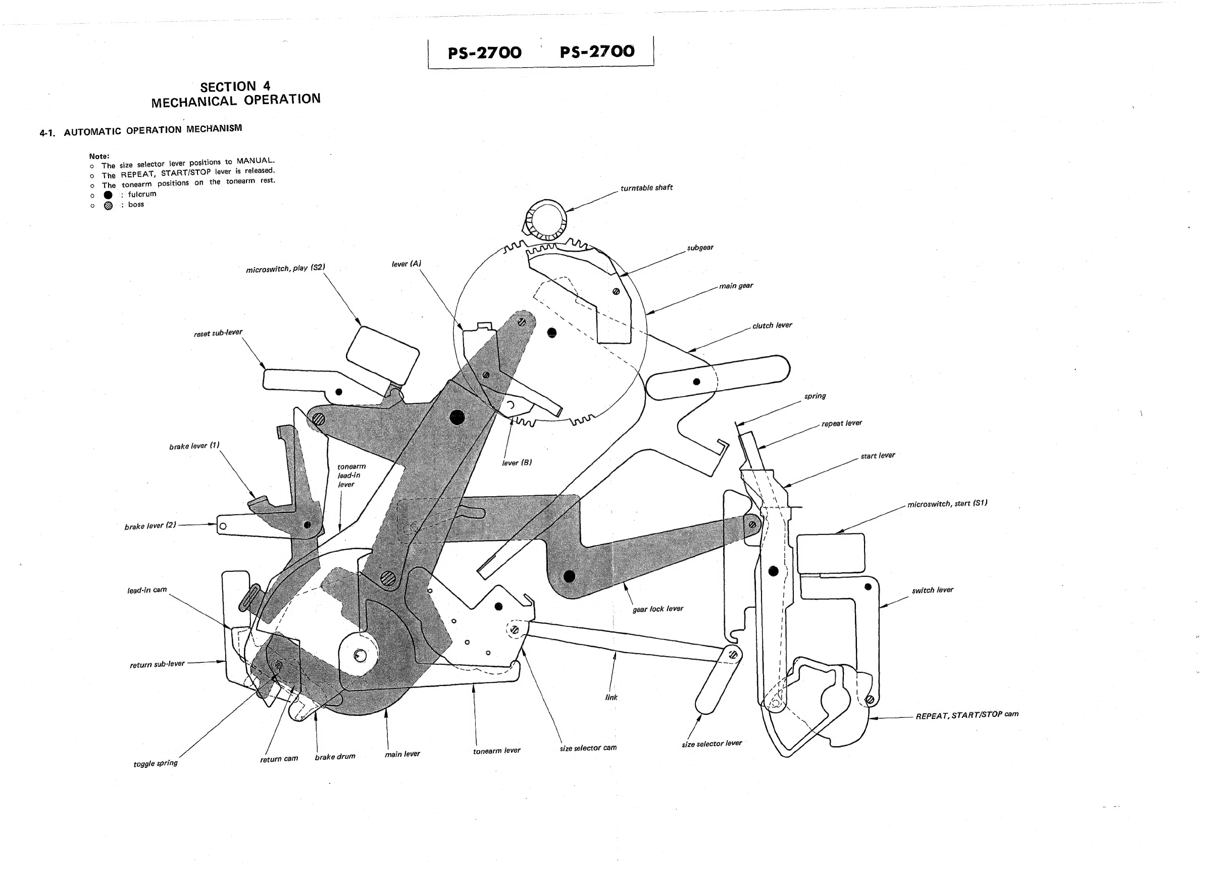
Sony PS-2700 User manual

GENERAL
Power
Requirement:
Power
Consumption:
Dimensions:
SPECIFICATIONS
110,
120,
220
or
240
V
ac,
50/60
Hz
(E,
AEP
mode!)
120V
ac,
GOHz
(US
and
Canadian
model)
OW
(E
model)
12W
(US,
Canadian
model)
18W
(AEP
model)
455
(w)
x
160
(h)
x
370
(d)
mm
18
(w)
x6
34h)
x
14%
(d)
inches
Weight:
Approx.
8kg,
17
Ib
10o0z
(net)
Approx.
10.5kg,
23
Ib
2
oz
(with
shipping
carton)
TURNTABLE
Platter:
30cm
(12
inches),
diecasting
aluminum
alloy
Drive
System:
_
belt
drive
Speeds:
3314,
45
rpm
Wow
and
Flutter:
S/N
Ratio:
+0.08%
(DIN
45507,
weighted)
Less
than
0.06%
(NAB,
weighted
rms)
Greater
than
63dB
(DIN
45539,
B-curve
weighted)
SAFETY-RELATED
COMPONENT
WARNING
!!
COMPONENTS
IDENTIFIED
BY
SHADING
ON
THE
SCHEMATIC
DIAGRAMS
AND
IN
THE
PARTS
LIST
ARE
CRITICAL
TO
SAFE
OPERATION.
REPLACE
THESE
COMPONENTS
WITH
SONY
PARTS
WHOSE
PART
NUMBERS
APPEAR
AS
SHOWN
IN
THIS
MANUAL
OR
IN
SUPPLEMENTS
PUBLISHED
BY
SONY.
TONEARM
Type:
Statically
balanced,
universal
Arm
Length:
300mm
(11
inches),
overall
216.5mm
(8
%
inches),
pivot-to-stylus
Overhang:
16.5mm
(*%,
inches)
Tracking
Error:
+3°,
_1°
Tracking-force
Adjustment
Range:
O-—3g
Shell
Weight:
7.59
Cartridge
Weight
Range:
4-—
10g
CARTRIDGE
(VL-32G)
(Canadian,
E,
AEP
mode!)
Moving
magnet
type
4mV
at
1kHz,
5cm/s
50k
ohms
Tracking
Force:
2g
Stylus:
Conical
0.5
mit
diamond
(ND-134G)
Weight:
5.59
SON
Y.
SERVICE
MANUAL
Type:
Output
Voltage:
Load
Impedance:
@

PS-2700
|
MODEL
IDENTIFICATION
—
Specification
Label
—
US,
Canadian
model
STEREO
TURNTABLE
SYSTEM
MODEL
NO.
PS-2700
AC
120V
60Hz
12W
SERIAL
NO.
MADE
IN
E
model
STEREO
TURNTABLE
SYSTEM
MODEL
NO.
PS-2700
AC
110,
120,
220,
240V
50/60Hz
10W
SERIAL
NO.
MADE
IN
AEP
model
STEREO
TURNTABLE
SYSTEM
MODEL
NO.
PS-2700
~
110, 120,
220,
240V
50/60Hz
18W
SERIAL
NO.
MADE
IN
JAPAN

PS-2700
SECTION
2
DISASSEMBLY
WARNING
Unplug
the
ac
power
cord
before
starting
any
dis-
assembly
or
replacement
procedures.
2-1.
TOP
COVER
REMOVAL
2-3.
BOTTOM
PLATE
REMOVAL
1.
Open
the
top
cover,
and
then
pull
it
up
as
shown
1.
Remove
the
turrtable
platter.
Don’t
remove
in
Fig,
2-1.
the
top
cover.
2.
Put
and
lock
the
tonearm
on
the
tonearm
rest.
3.
Place
the
set
up-side-down.
4.
Remove
four
foots
and
ten
tapping-screws
as
shown
in
Fig,
2-3.
oN
tapping-screw
P3
x
16
weak
part
“||
Take
care
to
handle.
bottom
plate
Fig.
2-1
2-2,
TURNTABLE
PLATTER
REMOVAL
1.
Remove
the
turntable
platter
mat
from
the
turn-
table
platter.
2.
Turn
the
turntable
platter
so
that
the
either
hole
Fig.
23
---
Of
the
turntable
platter
is
on
the
motor
pulley.
3.
Remove
the
drive
belt
and
then
lift
the
turntable
2-4.
CASE
REMOVAL
straight
up.
1,
Remove
the
bottom
plate
as
described
in
Pro-
top
cover
cedure
2-3,
2.
Remove
four
screws
and
pull
the
cord
holder
off
as
shown
in
Fig.
2-4.
‘
»
PSW
4
x
30
turntable
platter
mat
turntable
platter
hole
ae
Xx
ator
pulle
.
m
pulley
Fig.
2-2
Ye
holder
Note:
‘
The
motor
mechanism
is
locked
by
two
red-painted
Fig.
2-4
transit
screws.
When
operating
the
player,
remove
two
screws
and
keep
it
in
the
place
marked
*
in
Fig.
2-2.

PS-2700
2-5,
SHELL
HEAD
REMOVAL
Note:
The
four
lead
wires
for
shell
head
difficults
to
pass
through
the
tonearm
pipe.
Thus,
use
the
former
lead
wires
when
replacing
the
shell
head,
1.
Unsolder
the
output
leads
from
the
tonearm
on
the
terminal
board
as
shown
in
Fig.
2-5.
2.
Remove
the
bottom
plate
and
the
turntable
platter.
3.
Remove
two
shell-head-adjust-screws
as
shown
in
Fig.
2-6.
4,
Pull
out
the
shell
head
connector
about
3cm
ad
A
inches)
slowly
while
pushing
the
four
leads
into
the
tonearm
pipe
from
the
tonearm
base
side,
;
5.-Unsolder
the
four
leads
and
then
replace
the
shell
head.
Temporarily
secure
with
two
screws
as
shown
in
Fig.
2-6.
6.
Install
the
cartridge
to
the
tonearm.
7,
Fix
two
shell-head-adjust-screws
after
making
sure
that
the
position
of
cartridge
is
as
shown
in
Fig.
2-7,
grounding
wire
lead
RED
GRN
BLU
WHT
terminal
board
to
tonearm
Fig.
2-5
shell
head
connector
four-pin
connector
tip
of
screwdriver
hole
washer
17,.5mm
dia,
Fig,
2-6
RED
WHT
cartridge
B
GRN
ne
surtace
of
record
screw
right
angle
Fig,
2-7
2-6.
TONEARM
REMOVAL
1,
Remove
the
top
cover,
the
shell
head,
the
counter-
weight,
the
turntable
platter,
the
bottom
plate
and
the
case.
2.
Unsolder
the
leads
from
the
tonearm
on
the
terminal.
3.
Pull
out
the
grounding
wire
as
shown
in
Fig,
2-8.
4.
Loosen
two
hexagonal
screws,
then
remove
the
brake
drum
as
shown
in
Fig.
2-8.
5.
Remove
three:
hexagonal
screws,
then
draw
out
the
tonearm
base
while
turning
it
clockwise
about
2mm
on
the
circumference
as
shown
in
Fig.
2-9,
6.
Remove
the
tonearm
carefully,
brake
drum
hexagonal
screw
3
x
6
Fig.
2-8
hexagonal
screw
3
x
6
tonearm
base

2-7,
TONEARM
PIPE
REMOVAL
1,
Remove
the
tonearm
as
described
in
Procedure
2-6.
2.
Remove
the
12mm
dia.
retaining
ring
for
taking
”
off
the
tonearm
as
shown
in
Fig.
2-10.
3,
Replace
the
pipe,
the
rubber
for
pipe
and
the
connector
as
shown
in
Fig.
2-11.
4,
Temporarily
secure
the
pipe
with
two
hexagonal
screws
and the
screw
B2.6
x
6
as
shown
in
Fig.
2-11.
5,
After
replacing
the
new
arm
pipe,
install
the
tone-
arm
so
that
the
three
portions
of
A,
B
and
C
keep
the
same
height
as
shown
in
Fig.
2-12.
6.
Remove
the
tonearm
again
from
the
tonearm
base.
Fix
two
hexagonal
screws
and
the
screw
tonearm
base
retaining
ring
or
12mm
dia.
v
Fig.
2-10
B2.6x6
\
hexagonal
screw
}
tonearm
2.6x4
@
hole
for
screw
hexagonal
screw
re)
2.6x4
—~
tonearm
pipe
connector
rubber
for
pipe
tonearm
pipe
Fig.
2-11
tonearm
pipe
surface
of
player
A
B
c
7
PS-2700
2-8,
COUNTERWEIGHT
SHAFT
REMOVAL
@
rebber
damper
AS
counterweight
shaft
tonearm
body
Fig.
2-13
Note:
Install
the
shaft
slot-side-up
certainly.
2.9,
LATERAL
BALANCER
REMOVAL
Loosen
the
lateral
balance
nut
at
first,
and
then
remove
the
lateral
balance
shaft.
tonearm
body
@
hexagonal
screw
/
2.6x4
lateral
balance
nut
@
lateral
balance
shaft
@
lateral
weight
Fig,
2-14
Note:
The
lateral
balance
shaft
should
be
jut
out
a
few
inches
from
the
lateral
weight.
Also,
keep
the
lateral
weight
right
angle
against
the
tonearm
body
as
shown
below,
tonearm
body
right
angle
lateral
weight
Fig.
2-15

PS-2700
2-10.
MAIN
GEAR
REMOVAL
2-12,
TURNTABLE
SHAFT
BEARING
1,
Remove
the
turntable
platter.
1.
Remove
the
turntable
shaft.
2.
Set
the
main
gear
as
shown
in
Fig.
2-16.
2.
Remove
the
nut
as
shown
in
Fig.
2-17.
3,
Remove
the
E-ring
(E5)
3.
Replace
the
turntable
shaft
bearing.
4,
Replace
the
main
gear.
rotler
sub-gear
4
main
lever
Turn
the
main
gear
in
direction
arrow.
lever
(AJ
main
gear
Fig.
2-16
Note:
o
Don’t
forget
to
install
the
roller.
©
The
roller
should
be
geared
with
the
slot
of
the
heart-shaped
cam
accurately.
o
The
sub-gear
and
the
lever
(A)
should
be
moved
smoothly
and
kept
a
horizontal
motion.
2-11.
CENTER
SHAFT
REMOVAL
turntable
shaft
grease
(CR-10:
7-662-001-11)
nut
é
|
a
turntable
shaft
bearing
ce
x5
Fig,
2-17
Note:
o
When
installing,
lubricate
the
turntable
shaft
with
grease.

|
PS-2700
}+§%|$j-~S-2700
|
SECTION
3
ADJUSTMENT
TONEARM
LEAD-IN
POSITION
ADJUST-
MENT
Remove
the
rubber
cap
on
the
tonearm
base.
Adjust
the
adjustment
screw
for
the
tonearm
lead-in
lever
with
a
slot-screwdriver
so
that
the
stylus
lowers
correctly
on
the
record
at
fully
automatic
operation,
slot-screw
driver
rubber
cap
tonearm
base
move
to
inside
a
!
move
to
outside
adjustment
screw
lead-in
lever
TONEARM
HEIGHT
ADJUSTMENT
When
the
tonearm
is
lifted
up
with
the
arm
lefter
at
manual
operation,
adjust
the
hexagonal
screw
as
shown
below.
4~10mm
es
record
(5/32
~
13/32”)
arm
lifter
AUTOMATIC
RETURN
POSITION
ADJUSTMENT
.
Remove
the
turntable
platter
mat
and
the
turntable
platter.
.
Put
the
tonearm
on
the
arm
rest.
.
Disconnect
the
power
cord,
then
set
the
REPEAT,
START/STOP
control
to
START/STOP
position,
Turn
the
turntable
shaft
clockwise,
engage
the
main
gear
with
the
turntable
shaft.
Then,
turn
the
main
gear
once
to
detach
it
from
the
turntable
shaft.
4,
Set
the
lever
(B)
in
direction
arrow
marked
*,
.
Fit
the
return
adjustment
jig
(Part
Number
9-911-814-01)
in
the
turntable
shaft.
.
Adjust
the
automatic
return
position
adjustment
screw
so
that
the
stylus
position
is
61
to
64mm
on
the
return
adjustment
jig
when
the
tip
of
lever
(A)
touches
the
turntable
shaft
as
shown
in
figure.
.
Make
sure
that
the
return
action
is
done
completely.
center
of
shaft
lever
(A)
square
hole
for
drive
gear
square
hole
for
lever
(A)
COUGH
this
point
to
the
square
hole
sto,
a
touch
the
lever
(A)
to
turntable
shaft
.
the
main
gear
center
of
shaft
lever
(B)
ANTI-SKATING
FORCE
COM-
PENSATOR
ADJUSTMENT
BRAKE
LEVER
ADJUSTMENT
Set
the
size
selector
lever
to
MANUAL.
Adjust
the
adjustment
screw
as
shown
below
at
stop
mode,
Fix
the
hexagonal
screw
so
that
L
wrench
goes
along
the
center
line
on
the
tonearm
weight
adjustment
screw
shaft
as
shown
below.
tonearm
shaft
hexagonal
screw
anti-skating
2.6x3
hexagonal
screw
force
lever
2.4x4
tonearm
weight
L
wrench
shaft
2~5mm
(5/64
~
13/64”)
center
line
BRAKE
DRUM
POSITION
ADJUSTMENT
Adjust
the
hexagonal
screw
as
shown
below
when
the
tone-
arm
puts
on
the
arm
rest.
in
parallel
nearm
return
adjustment
Jig
rear
of
frame
Fiexagonal
screw
brake
drum
3x6
adjustment
screw

SECTION
4
MECHANICAL
OPERATION
4-1,
AUTOMATIC
OPERATION
MECHANISM
Note:
o
The
size
selector
lever
positions
to
MANUAL.
The
REPEAT,
START/STOP
lever
is
released.
°
o
The
tonearm
positions
on
the
tonearm.
rest.
o
@
:
fulcrum
o
@
:
boss
microswitch,
play
(82)
reset
sub-lever
prake
lever
(1)
fever
(A]
PS-2700
tonearm
lead-in
lever
prake
lever
(2)
lead-in
cam
return
sub-lever
toggle spring
return
cam
brake
drum
main
lever
lever
(B)
tonearm
lever
PS-2700
size
selector
cam
turntable
shaft
subgear
main
gear
size
selector
lever
clutch
lever
spring
repeat
lever
start
lever
@
microswitch,
start
(S1)
switch
lever
REPEAT,
START/STOP
cam

PS-2700
PS-2700
turntable
shatt
Note:
©
The
size
selector
lever
positions
to
MANUAL.
°
The
REPEAT,
START/STOP
lever
positions
to
START.
4.2,
MANUAL
LEAD-IN
OPERATION
seen
ee
ls
©
Meaning
of
symbol
mark
before
playing
or
during
playing
after
playing
————
operating
in
direction
arrow
)
return
action
These
symbol
marks
are
applicable
in
Pro-
cedures
4-2
to
4-5.
he
main
lever
pushed
out
by
the
heart-shaped
cam
of
the
main
gear,
(5)
The
subgear
pushed
across
‘o
the
turntable
shaft
by
;
e
clutch
lever,
e
turntable
shaft
thus
‘ates
the
main
gear.
2
switched
ON
when
he
main
lever
pushed
Both
S1
and
S2
owON
simultane-
ously.
main
gear
brake
lever
(2)
The
main
lever
exerts
pressure
against
the
brake
lever
(2)
throughout
full
stroke
action.
Only
mechanism
ci
with
tonearm
desi
operates
(PLAY)
The
spring
pushes
against
e
Clutch
lever,
9)
The
main
lever
pushes
against
gear
lock
lever.
@
gear
lock
lever
pushes
inst
the
start
lever
to
The
brake
lever
(1)
moves:in
brake
lever
(1)
unison
with
the.brake
lever
(2).
OF
P
<
@
start
lever
46
The
tonearm
is
braked
slightly
to
prevent
lateral
slipping.
(The
tonearm
will
slide
gently
across
to
the
record).
(3)
Motor
starts
turning
when
mo?
switched
ON.
microswitch,
start
(S1)
The
brake
lever
(1)
released
when
the
main
lever
reaches
final
position,
so
tonearm
also
released
from
the
brake
fever.
oa
,
/
tonearm
spring
also
falls
back
to
size
selectorcam
|
~_°
inal
position
together:
a
16
NU
switch
lever
REPEAT,
lead-in
cam
The
lead-in
cam
attached
to
the
main
lever,
pulls
the
tonearm
lead-in
lever
up
to
this
point,
where
‘he
cam
is
consequently
leased.
(The
tonearm
REPEAT,
START/STOP
cam
also
returns
to
original
position.
The
switch
lever
moves
Start
mode
is
completed,
outwards.
Play
mode
takes
over.
return
sub-lever
.
When
the
main
lever
reaches
gi NE
Net
final
position,
changes
from
,
Pull
REPEAT,
Miaka
re
ae
horizontal
(tonearm
UP)
to
inwards.
START/
STOP
a9
ven
if
the
return
cam,
:
slanted
{tonearm
DOWN),
f
lever
forward,
}
:
thus
causing
the
tonearm
to
pushes
“thee
ara
'
sls
aa
ppt
ree
REPEAT,
START/STOP
cam
return
sub-lever,
m
Fe
0
pos
aga
ee
the
The
lower
tip
of
the
ann
stops
in
this
position.
together
with
the
main
FANE
10
TEBOINESS
SOF:
lifter
is
located
here,
the
return
operation.
lever,
it
will
not
reach
this
pin.

PS-2700
PS-2700
4-3,
FULLY
AUTOMATIC
LEAD-IN
OPERATION
subgear
ubgear
pushes
across
é
turntable
shaft
b
Note:
7
ur
.
©
Diagram
indicates
example
for
30cm
(12
inches)
se
baci
by
the
heart-shaped
cam
of
©
Put
a
record
on
the
turntable
platter,
and
unlock
the
main
gear.
the
tonearm.
main
lever
Grate
micraswitch,
play
(S2)
clutch
lever
he
brake
lever
(2)
thout
full
stroke
action.
brake
lever
(2)
brake
fever
(1}
start
lever
tor
starts
turning
when
(1)
The
brake
lever
(1)
moves
‘itched
ON,
g
in
unison
with
the
brake
microswitch,
start
(S17)
lever
(2).
30cm
(12
inches)
|
disk
operation
|
point
The
tonearm
is
braked
slightly
to
prevent
lateral
slipping.
\
XN
@
N
Sem
(10
inches)
x
disk
operation-~
—~
—
a2
Fhe
spring
also
falls
back
to
original
position
together
with
the
start
lever,
Mechanism
concerned
with
tonearm
descent
operates
(PLAY).
a?
The
brake
lever
(1)
released
1
when
the
main
lever
reaches
t
final
position,
so
the
tonearm
S\
also
released
from
the
brake
lever.
REPEAT,
RT/STOP
cam
(3
REPEAT.
STARISTOP
aly
a/so
returns
to
Original
|
POsition,
size
selector
cam
17cm
(7
inches)
disk
operation
point
lead-in
cam
The
lead-in
cam
attached
to
the
main
lever,
pulls
the
‘onearm
fead-in
lever
up
to
point
which
is
30cm
inches}
disk
operation.
Start
mode
is
completed,
play
mode
takes
over,
tonearm
lead-in
The
switch
lever
moves
lever
outeards.
rd)
When
the
main
lever
reaches
final
position,
changes
from
@
t
the
si.
e
front
edge
of
horizontal
(tonearm
UP)
to
ey
Hy
a
HHOCHOr
deve
t0
The
start
lever
moves
|
Pull
REPEAT,
START/
?
e
fro.
rd
the
lead-out
groove
slanted
(tonearm
DOWN),
inwards,
STOP
lever
forward,
the
bit
marae
oan
te
ri
and
the
tonearm
lead-in
F
thus
causing
the
tonearm
to
(12
inches)
disk
operation.
lever
parts
from
the
lead-in
The
main
lever
raises
up’
commence
its
descent.
ition
j
cam
at
*
mark
point,
the
the
return
cam,
and
pulls
The
lower
tip
of
the
arm
REPEAT,
START/STOP
hen
the
tonearm
3
i
,
is
5
oe
:
rp
Aicst
ios
eon
hah
7s
:
hae
lead-in
cam
pushes
the
tone-
back
here
to
commence
lifter
is
located
here,
cam
stops
in
this
position,
arm
lead-in
lever
several
the
tonearm’s
descent.
inches,
Thus
freeing
the
tonearm
from
the
tonearm
lead-in
lever,
(The
tonearm
keeps
balance
here
because
jt
is
braked.}
completion
of
lead-in,

PS-2700
PS-2700
turntable
shaft Start
of
return
action
4-4,
AUTOMATIC
RETURN
(EXCLUDING
REPEAT)
OPERATION
sere
@:
‘When.the.stylus
enters
the
lead-out
groo
Ve
CLE
the
lever
(A}
makes
a
much
greater
advance
and
strikes
against
the
kick
portion,
thus
starting
up
the
main
gear.
BX
fly
part
\
gap
C
lever
(A)
Voi
si
Bil
B
ie
These
B
parts
are
the
first
parts
to
strike
the
turn-
@
clutch
lever
7
Note:
©
Stylus
enters
record
lead-out
groove.
©
Diagram
inclicates
example
for
17cm
(7
inches)
(EP)
record.
The
main
gear
rotates
in
the
direction
of
the
arrow.
ittle
by
little
with
each
The
main
gear
pulls
the
olution
of
the
turntable
main
lever
inwards
by
means
of
the
heart-shaped
cam
of
the
main
gear.
So
the
main
gear
is
not
ted
until
the
stylus
ches
the
lead-out
ove.
use
rea
i
microswitch,
play
(S2)
After
S2
switched
OFF
at
the
end
of
the
whole
operation,
the
reset
sub-
lever
remains
pressed
against
the
main
lever.
table
shaft,
thus
resetting
the
lever
(A).
_—
one
;
Ha”
cece
/
as
spring
Ithough
the
spring
pushes
against
the
clutch
lever
at
ee
first
by
means
of
the
gear
Jock
lever
action,
the
lever
(A)
is
reset
because
theB
~
\
parts
are
the
first
parts
to
strike
the
turntable
shaft.
The
initial
push
action
is
ineffective.
7
gear
lock
lever
-
As
soon
as
the
stylus
approaches
the
record
lead-out
groove
(61—-64mm
from
center
of
record),
the
tonearm
lever
pushes
against
the
clutch
lever,
which
in
turn
pushes
the
clutch
(A)
towards
the
fly
part
of
the
turn-
table
shaft.
The
tonearm
slides
smoothly
across
to
the
arm
rest,
with
e
a
slight
brake
applied.
y
-
Tonearm
return
tonearm
lead-in
lever
tonearm
lever
lead-in
cam
“fhe
tonearm
lead-in
lever
in
pushed
by
the
frame
\A
Of
the
lead-in
cam
at
first,
then
catching
it
in
the
hollow
part
of
i
cam,
®M
The
main
lever
advances
ay
to
the
left,
and
the
tonearm
-
lifts
away
from
record.
&
~~
(Anangle
of
5
required
for
the
tonearm
to
lift
up).
tonearm
lead-in
The
rete
lever
pin
oe”
{
inwards
~~
eee.
ae
Position
when
the
tonearm
f
/
ea
a
.
aa
)
ORs
jon
wi
[~~
3
KG
return
cam
Lifting
of
the
tonearm
ces
A
:
cam,
and
returning
the
~®@
bi
teprevearee
nrc
this
:
pag
Geen”
return
cam
to
the
left.
will
not
commence.
It
simply
advances
to
the
left.
point
by
means
of
pin
A.

4-5.
REPEAT
OPERATION
Note:
©
The
diagram
j4lustrates
the
operation
from
just
turntable
shaft
before
the
tonezarm
returns
to
the
arm
rest
through
to
the
commencement
of
lead-in.
Positions
at
tive
end
of
fead-in
are
also
shown.
subgear
‘ince
the
clutch
lever
has
i
:
ady
been
pushed
out,
aia
as
|
the
slbger
plate-bearer
sectionslides
up
the
clutch
5
The
subgear
fills
up
the
no-
09
section
of
the
main
fear,
and
the
main
gear
startisto
rotate
again
for
main
gear
microswitch,
play
(S2)}
;
=
~
Sa.
fever
\
oe
.
Once
the
lead-in
process
At
the
end
of
auto
return,
|
\
commences,
the
gear
lock
the
shoulder
of
the
subgear
e@
repeat
lever
lever
pushes
the
repeat
jis
pushed
inwards
by
the
lever
back
its
original
cogs
of
the
turntable
shaft,
position,
thus
freeing
thus
resetting
the
subgear,
the
clutch
lever,
(At
the
end
of
the
auto
return
pracess,
S2
switched
OFF,
but
$1
remains
ON.)
The
repeat
lever
is
pushed
back
by
the
gear
lock
lever
during
play,
so
it
does
not
make
contact
with
the
clutch
lever.
(In
the
repeat
operation,
the
switch
fever
is
pushed
;
out
by
the
REPEAT,
‘eturns
its
original
Positio
in
the
auto
return
operation,
the
repeat
lever
is
advanced
forward,
pushing
agianst
the
clutch
lever.
START/STOP
cam,
and
S7
remains
ON
even
after
auto
return
operation.)
microswitch,
start
(S7)
E/
clutch,
3
fever
\
Position
when
the
tonearm
has
returned,
tonearm
fever
.
gear
lock
lever
{When
the
stylus
enters
the
lead-in
groove.)
Positions
after
the
tonearm
has
returned
to
the
arm
rest
by
the
auto
return
process.
\
Repeat
process
frepeated
Jead-in}
(When
the
tonearm
is
back
{During
other
on
the
arm
rest.}
1g
Other
processes
apart
from
repeat,
the
front
edge
of
the
repear
lever
is
Pushed
to
this
position
by
REPEAT,
STAR/STOP
cam,
The
main
lever
and
the
return
ii
aha
dae
cam
position
during
play.
lever
is
not
moved
any
more.)
REPEAT,
START/STOP
cam
switch
lever
tonearm
lever

PS-2700
PS-2700
!
SECTION
5
DIAGRAMS
Ee
ee
a
Note:
The
components
identified
by
shading
are
critical
for
safety.
Replace
only
with
part
number
specified.
US
model
Canadian
model
CARTRIDGE
OUT
GROUND
ae
|
RELAY
BOARD
5
YEL
TO
MOTOR
FRAME
TERMINAL
BOARD
ARM
SHAFT
CARTRIDGE
OUT
CONNECTOR
PIN
(REAR
SIDE)
SCREW
HOLE
RELAY BOARD
CARTRIDGE
OUT
cgrounD
RL
aia
BOARD
E
model
AEP
model
nites
“The
aaiaponeit
identified
by
shading
are
critical
for
safety.
Replace
only
with
part
number
specified.
sity
Sac
Note:
©
~fw}
:
nonflammable
resistor.
AEP
MODEL
VOLTAGE
SELECTOR
eee
Se
a
eee
BRN
~
|
|
1
AC
IN
|
|
|
|
|
|
E
MODEL
fae
|
|
bac
in__-—WHt
|
|
|
©
bree
WHT
|
oo
SS
R3
er:
390(5W)
—N
FF
=a
a
NEL
ok
Q
WHT
POR
WaT
S1
PLAY
S2.
START
:
FSS
-1024B

PS-2700
PS-2700
|
SECTION
6
EXPLODED
VIEW
B
Counterweight
Ass’'y
SC2.6x4
4844-053-00
©
:
h
ial
screw
t,
counterweight
©
Rema
4-844-038-00
4-844-051-00
pia
163-00
j
Nut
(8),
pivot
securing
Damper,
rubber
eight,
(aera!
4:844-037-00
®
4.844.052.00
()
>
Nut
(Aj,
pivot’securing
Bushing
2-203-518-00
Screw,
pivot
a
2-226-407-00@)
ca
|
4-844-054-00
®)
Shaft,
lateral
balance
®
'
i
Spring,
guide
2-226-408-00
NL
Nut,
lateral
balance
1-608-620-00
K<"
\g
Connector,
tonearm
pipe
\
"|
4:844-046-00
(A)
Washer,
rubber
.
j
&,
4-844-045-00
=
Pipe,
penton)
pate
2-085-082-00
(@)
X-4844-017-2
©
(CVF
17x23
ee
Nut
(8),
pivot
securing
Washer,
11.5
mm
dia
4-844-037-00
(@)
_
2-085-058-00
C)
Nut
(A),
pivot
securing
Collar,
locking
SC
2,6
x
4,
SC2.6x4
1-509-550-00
hexagonal
screw
hexagonal
screw
Connector,
sfrell
head
4-844-102-00
©
Body,
tonearm
2.203-530-00
@)
;
Damper,
pivot
bearing
2-203-528.00
®)
Screw,
shell
head
adj.
2-203-529-00
Bearing,
pivot
4-847-059-00
Screw,
cartridge
i
oe
®
(Canadian,
E,
AEP
model)
3701-438-2
1®
ae
®
fasher,
cartrs
asher,
2.081-731-00
(Canadian,
E,
AEP
model)
Washer,
shell
head
X-4844-012-0
(H)
hell
Head
Ass‘y,
including
parts
marked
MA
~
E
2.227-313-00
@)
Spacer,
cartridge
(Canadian,
E,
AEP
model)
1-549.073.00
©)
Cartridge,
VL-32G
\
(Canadian,
E,
AEP
model}
a
aA
X-2089-618-1
{red)
®
:
X-2089-618-2
(green)
®
X-2089-618-3
(white)
(@)
Gs)
a
2.815.656.0208
Nut,
cartridge
X-2089-618-4
(blue)
®
(Canadian,
E,
AEP
model}
Lead
Wire
Ass‘y,
shell
head
,
E,
o
Sz
3.705:801-00
@
-549-074-00
‘over,
stylus
Syl,
(Canadian,
E,
AEP
model)
4-847-074-00
Lever,
anti-skating
force
compensator
Stylus,
ND-134G
(Canadian,
E,
AEP
model)
7-624-183-01
Retaining
Ring,
12mm
dia
Plate
Ass’y,
ground
|
x-4847-024.0
O
Shaft
Ass’y,
tonearm
4,844-043-11
Knob,
anti-skating
force
compensator
4-844-041-00
Washer
®
4-847-006-12
(O)
Tonearm
Base
4-844-039-00
Cam
(A),
anti-skating
force
compensator
4-844-040-00
®
Cam
(8),
anti-skating
force
compensator
L
4844-04-00
(A)
Spring
W
3
flarge)
©
4847.040.00
®
Cap,
cam
P3x
12,
self-tapping
Note:
°
Items
with
no
part
number
and/or
no
description
are
not
stocked
because
they
are
seldom
required
for
routine
service.
All
screws
are
Phillips
(cross
recess)
type
unless
otherwise
noted.
The
circled
letters
{
@)
to(Z))
are
appli-
cable
to
European
model
only.
4843-73200
©)
Mat,
turntable
platter
3x6,
x-4845-502-3
©)
hexagonal
screw
Cover
Ass‘y,
top
x-4847.009-08)
Arm
Lifter
Ass'y
SC2.6x
4,
hexagon
socket
4sss.001.00
\
(>
X-4847-013-0
.
Platter,
turntable
\
Shaft
Ass’y,
tonearm
lifting
48
i
47-01
7-0'
no
‘
Shifter,
drive
belt
18-489-00
©)
x-4847.017-0©
Belt,
drive
&3
5
ane
Damper,
shifter
3-793-424-12
Label,
caution;
transit
screw
Stand,
shell
head
Gear,
main
Lever
Ass’y,
arm
lifter
|
X-4847-018-08)"
Holder
Ass’y,
arm
5
gee
/
wees
SCO
3x3
2:203-623-00
]
|
B3x
8,
Clamper,
arm
solf-etapping
4808-459:21
@)
SY
—
4.347-755.00
faox
5,
H
j
Screw,
transit
©
—Voltage
indication
card
4:847-503-00
selftepping
701-441-218)
4-847-055-00
)
Washer,
thrust
Per
rr
Spring
4.815-486-00@)
4247-50400
©
Washer,
plastic
~~
Knob,
REPEAT,
Me
STAAT/STOP
~
fe
‘es
45
1rpm
adaptor
Ss
2.064-121-00
®)
i
Card,
60Hz
2064-12200
Card,
§0Hz
4847-5050
©
Escutcheon,
knob
3-536-772-00
Spring
®
,
™
ia
'x-4843-708.0)
es
2
Bers
Shaft
Ass‘y,
tarntable
83x8,
oy
we
4843716-00
seif-tapping
Shaft
(4),
stepped
ee
(el
4-847-054-00.
X-4827-407-0
Subgear
Laver
Assy
(8B)
4847-002-00
Link,
shifter
cs3
e282
00
@,
Lever
Ass‘y,
gear
4-844-074-00
@)
vena
7
tock
Spring
x-4847-504.0
©
Lever
Ass’y,
main
4-847-035-00
@)
Cushion,
tube
x-4847-510-0
©
3-701-437-11
®
Bearing
Ass’y,
turntable-—
Washer,
plastic;
shaft
PTTWH
3.x
8}
4-847-553-00
(US,
jan
model}
+
2mm
dia
‘
4-847-554-00
(E
model)
-
4-B47-016-00
PSP
3x
Oe
4-847-571-00
(AEP
model)
.
Spring,
toggle
®
Zz
Label,
specification
:
wood
E2
4847-024.00
X-4847-513-2
(US
model}
Cam,
return
X-4847-513-3
(Canadian
model}
X-4847-520-2
(E,
AEP
model}
(M)
Case
Ass’y,
including
parts
marked
@
A’
Ni
ote:
Plate
Ass’y,
bottom:
Label,
caution
4-837-008-00
®)
Self-tapping
Screw,
w/vasher
3701-891-00
@)
°
[tems
with
no
part
number
and/or
no
description
are
not
stocked
because
they
-are
seldom
required
for
routine
service.
©
All
screws
are
Phillips
(cross
recess)
type
unless
otherwise
noted.
(—)
=
slotted
head
©
The
circled
letters
(
@)
to
@)
are
appli-
cable
to
European
model
only.
X-4842-106-5
Foot
Ass’'y
®
I
DEE
ECS
ESSER
ae
.
Note:
The
components
identified
by
shading
are
critical
for
safety.
Replace
only
with
part
number
specified.
a
Ca
ee
ee
e
:
Bos

PS-2700
D
PTTWH
3x8
Ba
AS.
conan
Note:
7-5
12-00
.
per
eee
®
©
Items
with
no
part
number
and/or
no
pe
3.642-425.00
(8)
description
are
not
stocked
because
they
Sprit
ae
. .
joring
4202-10400
®
ori
gae.
-
4247-09000
®
are
seldom
required
for
routine
service.
1,
tube
a
=
sya:
men
L
vee
(2).
rake
®
©
All
screws
are
Phillips
(cross
recess)
type
¥
4-847-§62-00
‘
5
AEP
Spring
®
unless
otherwise
noted.
4-847-018-00
.
*
Pee
aes
-
i
ges
|
Spring
©
The
circled
letters
(
@)
to
@
)
are
appli-
ke
r,
p
'
hg
it
A
;
Oe
a
a
coinncn
©
Spring
Cam
Assy,
size
C&
cable
to
European
model
only.
%
|
\
g4
2s
L
‘
Bi
4.208-242.00
®
BIx
4
-
Lever
(1)
Ass’y,
brake
.
TES
er
Spacer
SeetO)
|
:
-
&
|
cover,
repeat
oes
4809.890-11
‘Soren
ee
PT
TWH
3x6
Oe
3-486-138-00
®
7
.
|
A
Shaft
(H),
stepped
emo.
4.847-544-00(8)
Spring
Lever,
start}
4847-520-00
|
4947.52000(B)
4-847-514-0018)
Spring
Lever
Ass’y,
clutch
'
4-847-505-00
©
Sub-lever,
reset
Cam,
repeat,
start/
stop
4-847-523-00
'
,
:
<
PS3x
14
|!
Lever,
size
selector:
Bracket,
printed
circuit
H
Bracket
Ass’y,
motor
4-00
®
if
board
7
QQ
PTTWH3x6
4803-18:
:
Cushion,
tube
|
Printed
Clreak
Board
sw3
4-847-513-00
Lug
3mm
dia
2.033-635-00
é
Spring
®
Washer
(8)
~~
~~!
Stee!
Bel!
4
mm
dia
Lea
ga
:
4847-561-00
|
y
uMicrose
Shaft
(J),
stepped
Spring
f—
-1,
3537-797-00
®)
Fiber,
insulator
i
X-4844-007-1
(60
Hz)
X-4844-007-2
(60
Hz)
Pulley
Ass'y,
motor
AEP
model
Holder,
power
cord
{
ee
ee
eee
(US,
Canadian
model)
:
Note:
The
components
identified
by
shading
are
critical
for
safety.
Replace
only
with
part
number
specified.
REE
9597-7970
Labes
|
mee
Fiber,
insulator
=
ra
(US,
Canadian
model}
|
™
Plate,
guide
AS
Wa
7
|
&4
~~]
PTPWH
3
a
oO
I
i
A
|
Sogn
te
:
Ge.
ee
|
ws
Yo
|
:
(“
|
|
Bracket,
POWER
switch
|
|
|
|
l
|
Board
Ass’y,
motor
{
|
3
|
|
|
|
E,
AEP
model
only
|
—
SS
ee
oy
eat
Cord,
phono
~
printed
circuit
board
|
|
|
|
| |
|
fuse
holder
|
4847-57200
|
|
Escutcheon,
POWER
switch
2
|
|
>
|
SBE
y
|
[
2
Holder,
phono
i
ee
|
|
“
mt
|
x-3524.133-0©)
ea
Knob,
POWER
switch
_|
|
=
|
boot
=
oes

PS-2700
SECTION
7
ELECTRICAL
PART
LIST
Note:
The
circled
letters
(@®
to
@
)
are
applicable
to
European
model
only.
Ref.
No.
Part
No.
Description
Ref.
No.
Part
No.
Description
3-701-806-01
®
Adaptor,
45
rpm
3-780-973-11
Manual,
instruction
(E,
AEP
model)
3-780-973-21
Manual,
instruction
(US
model)
3-780-973-21
|
3-794-030-31
3-793-395-00
Gauge,
overhang
adjustment
Manual,
instruction
(Canadian
model)
4-815-655-01
Nut,
cartridge
(US
model)
4-834-105-00
®
Sheet,
plastic
4-838-319-01
Screw
(middle),
cartridge
(US
model)
4-843-577-00
Sheet,
top
cover
4-844-059-00
Bag,
plastic;
platter
turntable
4-844-060-00
©
Bag,
plastic;
unit
4-847-092-00
©
Screwdriver
4-847-565-00
(©)
Cushion,
bottom
4-847-566-00
©)
Cardboard
4-847-568-00
(©)
Carton
4-847-569-00
©)
Cushion,
side
4-847-542-00
(8)
Cushion,
platter
turntable
rt
ss
a
1-509-550-0
©
Connector,
shell
head
9-911-851-XX
(E)
Cushion,
tonearm
pipe
(t3)
1-536-324-00
Terminal
Board
(US,
Canadian
model)
1-549-073-00
(©)
Cartridge,
VL-32G
(Canadian,
E,
AEP
model)
1-549-074-00
()
Stylus,
ND-134G
(Canadian,
E,
AEP
model)
1-551-063-00
(©)
Cord,
phono
ts)
ACCESSORIES
&
PACKING
MATERIALS
X-4847-522-0
(©
Carton
Ass’y
2-054-619-00
@)
Spacer,
cartridge
2-054-624-00
Screw
(large),
cartridge
(US
model)
2-054-625-00
Screw
(small),
cartridge
(US
model)
.
2-227-313-00
Spacer,
cartridge
(US
model)
{)
2-064-121-00
Card,
60Hz
2-064-122-00
Card,
50Hz
;
(:
3-701-438-21
Washer,
plastic;
2.5mm
dia
(US
model)
3-701-630-00
®
Bag,
plastic;
instruction
manual
sae
Eee
not
Note:
The
components
identified
by
shading
are
critical
for
safety.
Replace
only
with
part
number
specified.
Sao
a
Se
ve
Sony
Corporation
©
1977
9-958-339-12
;
7A0448-1
:
Printed
in
Japan
Table of contents
Other Sony Turntable manuals

Sony
Sony PS-X60 User manual

Sony
Sony PS-LX300USB - USB Stereo Turntable System User manual

Sony
Sony PS-DJ9000 - Stereo Turntable System User manual

Sony
Sony DD-57 User manual

Sony
Sony PS-2250 User manual

Sony
Sony PS-FL7II - Stereo Turntable Parts list manual

Sony
Sony PS-LX49 User manual

Sony
Sony NW-A25 User manual

Sony
Sony PS-LX250H User manual

Sony
Sony WALKMAN NW-ZX505 User manual