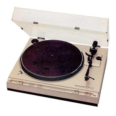
Marantz TT-6000 User manual

TT-6000
service
manual
2
|
iw”
—
CCT
8000
tote
Lecsemet
le
qadcta
divact
drive
sretem
as
2
os,
2
TT
#¢
tT}
-_—
=
=
«
ee
—
=
= =
me
oe

MARANTZ
DESIGN
AND
SERVICE
Using
superior
design
and
selected
high
grade
components,
MARANTZ
Company
has
created
the
ultimate
in
stereo
soun
Only
original
MARANTZ
parts
can
insure
that
your
MARANTZ
product
will
continue
to
perform
to
the
specifications
fe
which
it
is
famous.
Parts
for
your
MARANTZ
stereo
are
generally
available
within
72
hours
throughout
the
nation
via
a
toll-free
line
to
ot
National
Parts
Depot
in
California.
The
sales
professionals
who
take
your
call
immediately
refer
to
their
own
desk
top
cor
puter
terminal
and
can
quickly
determine
the
availability
and
price
information
you
require.
If,
for
some
reason,
your
ord
should
exceed
our
available
stock,
we
usually
can
instantly
provide
an
alternate
replacement
part
or
current
delivery
info
mation.
When
the
order
is
placed
and
confirmed,
the
computer
simultaneously
generates
‘‘hard
copy”
orders
at
the
distrib
tion
center.
As
hard
copies
come
directly
from
the
computer
to
the
national
parts
depot,
your
requested
stock
is
assemble
and
prepared
for
shipment
and
placed
on
the
first
available
carrier
for
delivery
to
you.
ORDERING
PARTS
Phone
orders
will
eliminate
mail
delays,
and
we
encourage
the
use
of
this
method.
If
you
order
by
mail,
use
MARANTZ
par
order
forms
which
are
available
from
our
National
Parts
Depot
located
at
the
following
address:
SUPERSCOPE
NATIONAL
PARTS
DEPARTMENT
20525
Nordhoff
Street
Chatsworth,
California
91311
Phone:
1-800-423-5108
1-213-998-9333
The
following
information
must
be
supplied
to
eliminate
delays
in
processing
your
order:
Complete
address.
Complete
part
numbers.
Complete
description
of
parts.
Model!
number
for
which
part
is
required
(indicate
MARANTZ).
Account
number
(for
account
customers
only).
PWN
>
Direct
consumers
will
be
provided
with
the
current
retail
price
quotation
on
available
parts
in
order
to
advise
them
of
the
co
of
the
parts
and
shipping.
OVERSEAS
PARTS
ORDERING
Parts
may
also
be
ordered
from
the
following
overseas
addresses:
CANADA
AUSTRALIA
JAPAN
Superscope
Canada,
Ltd.
Superscope
(Australasia)
Pty.,
Ltd.
Marantz
Japan,
Inc
3710
Nashua
Drive
32
Cross
Street
(P.O.
Box
604)
3622
Kamitsurumé
Mississauga
Brookvale
2100
N.S.W.
Sagamihara
Shi
Ontario,
Canada
L4V1M5
Australia
Kanagawa,
Japan
EUROPE
Superscope
Europe,
S.A.
Marantz
France
Marantz
Audio
U.K.
Ltd
Superscope
GmbH
Avenue
Leopold
Ill,
2
Rue
Louis
Armand
9
London
Road,
203
Max-Planck-Strasse
z
7120
Peronnes-Lez-Binche
92600
Asnieres
Staines
D-6072
Dreieich
1
Belgium
Hauts-de-Seine
Middlesex
West
Germany
7
France
England
Ail
of
the
above
locations
are
fully
equipped
to
take
care
of
your
total
service
needs.
Because
various
countries
have
differi
configuration
requirements,
it
is
necessary
that
you
contact
the
service
facility
in
your
particular
country.
In
the
event
th
there
is
no
service
location
listed
for
your
country,
please
contact
the
nearest
facility
for
the
necessary
assistance.
gids
Mpa
iereeeT
Bee
og
Tce
ted
owe
get
enek
OU
Aa
wie
cL
gts
Dk"
armas
aria
De
ete
ERE
DA
PB
rt
Babe
2
ayaa
cul
it
2
ga
alain
ee
a
BEG
29
Ae
ioBlAsiamatda
Ui
abe]
Laat
a
geld
ai
Ui
add
Hid
loa
pada
abate
ae
Denar
eae
aiah
paella
lj
ahh
dellgjpiha
a
Cee
aR
Rate
a
itt

INTRODUCTION
This
service
manual
was
prepared
for
use
by
Authorized
Warranty
Stations
and
contains
service
information
for
a
Marantz
Semi-Automatic
Quartz
Lock
TT-6000
Turn-
table.
Service
information
and
voltage
data
included
in
this
manual
are
intended
to
be
used
by
experienced
service
technicians,
knowledgeable
in
Turntable
designs
and
Ser-
vice.
All
instructions
should
be
read
and
no
attempt
to
repair
the
circuits
or
mechanisms
should
be
made
until
complete
operation
is
understood.
The
parts
list
in
this
manual
pertains
to
five
different
areas.
Be
sure
that part
numbers
for
your
respective
area
are
correct
before
parts
orders
are
placed.
A
simple
des-
cription
is
provided
for
parts
which
can
be
purchased
locally
or
through
the
Marantz
Parts
Facilities.
Refer
to
the
Marantz
Design
and
Service
Section
of
this
manual
for
correct
parts
ordering
methods.
TT-6000
SERVICE
MANUAL
CONTENTS
SUBJECT
MARANTZ
DESIGN
AND
SERVICE
.
CARTRIDGE
WIRE
COLOR
CODE
STYLUS
OVERHANG
ADJUSTMENT
STYLUS
TRACKING
FORCE
ADJUSTMENT
TONE
ARM
TRAVEL
ADJUSTMENT
PHOTO
CELL
DETECTION
CIRCUIT
LEAD
IN
ADJUSTMENT
ELEVATION
PLATE
ADJUSTMENT
.
ELECTRONIC
ADJUSTMENT
.
PHASE
LOCK
ADJUSTMENT
WOW
AND
FLUTTER
ADJUSTMENT
CIRCUIT
WAVEFORM
ANALYSIS
TT6000
TROUBLE
SHOOTING
CHART
TT6000
FINAL
ASSEMBLY
.
TT6000
WIRING
DIAGRAM
POWER
SUPPLY
CIRCUIT
BOARD
MOTOR
CONTROL
CIRCUIT
BOARD
SWITCH
CIRCUIT
BOARD
.
SWITCH
LOGIC
CIRCUIT
BOARD
CIRCUIT
VOLTAGE
CHARTS
.
TT6000
ELECTRICAL
SCHEMATIC
.
TT6000
SWITCH
LOGIC
CIRCUIT
SCHEMATIC
.
SWITCH
CIRCUIT
DESCRIPTION
.
AUTOMATIC
RETURN
CIRCUIT
DESCRIPTION
TT6000
MECHANICAL
ASSEMBLY
.
PARTS
LIST
.
TT6000
TECHNICAL
SPECIFICATIONS
PACKAGING
ASSEMBLY
PAGE
Oo
OnNnNN
OD
DN
FP
FF
WW
WWNY
YN
HY
NYDN
ND
=
a
ee)
=
©
©
12-13
14
14

ALIGNMENT
ADJUSTMENTS
This
service
manua!
was
prepared
for
qualified
tech-
nicians
familiar
with
turntable
maintenance
and
align-
ment
procedure.
Review
complete
adjustment
sec-
tions
before
proceeding.
CARTRIDGE
WIRE
COLOR
CODE
Before
installing
a
cartridge
to
the
headshell,
the
wires
should
be
connected
to
the
cartridge.
The
cart-
ridge
or
its
technical
sheet
will
identify
the
con-
nection
pins.
It
may
be
necessary
to
slightly
compress
the
terminal
clips
on
the
headshell
wires
with
your
fingers
to
firm
the
contact
area
to
the
pins.
Below
is
the
|headshell
color
description.
HEADSHELL
WIRES:
Right
Channel
Hot.................-.4--
Red
Right
Channel
Ground..................
Green
Left
Channel
Hot.
............
0.000
e
wees
White
Left
Channel
Ground....................
Blue
After
wire
connections
are
made,
install
the
cartridge
mounting
screws,
provided
with
the
cartridge,
through
the
mounting
slots
and
tighten
firmly
enough
to
hold
the
cartridge
in
place.
Final
adjustments
are
made
after
the
overhang
dimensions
is
adjusted.
A.
STYLUS
OVERHANG
ADJUSTMENT
A
45RPM
adaptor
is
supplied
with
the
TT-6000
turn-
table
that
will
be
used
for
adjusting
the
overhang
dimension,
An
arrow
is
marked
on
the
45RPM
adap-
tor,
and
a
gradient
scale
from
11
through
18.
1.
Place
the
adaptor
on
the
spindle
with
the
arrow
pointing
towards
the
rear
of
the
turn-
table.
The
gradient
scale
will
be
in
the
lower
left
quadrant
when
viewed
from
the
front.
2.
Remove
stylus
protective
cover
and
balance
the
tone
arm.
Place
the
tone
arm
to
the
gradient
scale
and
set
stylus
contact
to
gradi-
ent
17mm
on
the
45RPM
adaptor.
Set
the
cartridge
screws
after
checking
that
the
cart-
ridge
is
parallel
to
the
sides
of
the
headshell.
B.
STYLUS
TRACKING
FORCE
ADJUSTMENT
1.
Remove
the
stylus
protective
cover
and
adjust
the
counterweight
until
the
tone
arm
is
cap-
able
of
being
suspended
in
midair
without
movement.
2.
Set
the
counterweight
dial
to
zero.
3.
Rotate
the
counterweight
towards
the
pivot
point
to
the
manufacturer’s
specified
cart-
ridge
tracking
force.
4.
Adjust
the
anti-skate
control
to
the
same
amount
of
force
as
the
stylus
tracking
force.
TONE
ARM
TRAVEL
ADJUSTMENT
Changing
the
angle
of
the
feed
arm
assemble
deter-
mines
the
speed
of
the
tone
arm
travel.
NOTE:
Care
must
be
excercised
to
maintain
clearance
between
the
feed
arm
assembly
and
the
friction
rubber.
Refer
to
Figure
1.
FEED
ARM
CLEARANCE
FRICTION
RUBBER
FIGURE
1
Moving
the
Feed
Arm
Assembly
clockwise,
when
viewed
from
bottom
of
the
turntable,
slows
the
tone
arm
return
and
counter-clockwise
will
speed
the
return
travel.
Loosen
the
hexagon
set
screw
on
the
feed
arm
assy
(Refer
to
Figure
2)
and
turn
feed
arm
assy
in
increments
of
a
few
degrees
either
clock-wise
(slow),
counter-clockwise
(fast)
until
desired
travel
speed
is
set.
Re-tighten
set
screw
after
checking
clear-
ance
between
the
feed
arm
assy
and
the
friction
rubber
(2mm).
LEAD
-
IN
ADJUSTMENT
yw
ECCENTRIC
PIN
RETURN
ADJUSTMENT
ECCENTRIC
PIN
SELECTOR
ASSEMBLY
FEED
ARM
FIGURE
2
PHOTO
CELL
DETECTION
CIRCUIT
Install
the
tone
arm
in
its
rest
clip
and
turn
the
turntable
on.
Select
33RPM
MODE.
Adjust
voltages
below
in
the
Photo
Cell
Detection
circitit
VR1-D.C.
Voltage
between
Pins
9
and
10-0.2VDC
VR2-D.C.
Voltage
between
Pins
9
and
11-0.65VDC
After
the
tone
arm
travel
and
photo
cell
detection
circuit
is
adjusted
then
the
eccentric
pins
on
the
feed
arm
assy
can
be
used
for
fine
adjustment.
The
return
eccentric
pin
will
adjust
the
tone-arm
speed
return
while
the
Lead-in
eccentric
pin
will
position
the
tone
arm
during
lead
in
to
the
disc.
|
LEAD
IN
ADJUSTMENT
Adjust
disc
lead-in
dimension
by
turning
the
lead-in
eccentric
pin
on
the
feed
arm
assembly.
Turn
eccentric
pin
clockwise
to
adjust
tone
arm
away
from
the
disc
and
turn
counter
clockwise
to
move
the
tone
arm
toward
the
disc.
ELEVATION
PLATE
ADJUSTMENT
Cueing
elevation
of
the
tone
arm
is
adjusted
by
the
cueing
nut
located
in
the
cueing
lift
shaft
on
the
top
of
the
turntable.
Turning
the
cue
nut
clockwise
(viewed
from
the
top
of
the
turntable)
lowers
the
cueing
elevation
height
and
counter-clockwise
incre-
ases
the
elevation
height
of
the
cueing
arm.

‘
alyéh
j
S-
cack
BR
Sad
eae
eae
lsd
adecagedc@e
Ua]
ae
ed
ads
en
Ge
freee
pipet
cath
rahe
[SHEE
cet
Ghote
mo
tasted
ce
a
ag
We
atthe
goatee
2, Og
'
6
oN
Tag
ie
dg
WE
Seas
aie
cg
Pe
ere
ac
ee
eave
alee
Hef
igde
ee
Pee
pibe
es,
Be
caeutingin
cop
dg
dates
LS
ding
Hh
papel
ped
ia
chai:
SP
Hgcdy
betel
eapiedh
wee
Gia
dep
cde
fe
RUPE
bey)
PMc
Bg
asin
PHT
Aes
Ru:
ike
send
ULES
ETE
BUSS
AD
REE
PB
Bae
TH
ELECTRONIC
ADJUSTMENTS
Follow
alignment
sequence
for
electronic
adjustments
H
below.
A.
Supply
Voltage
Verification
B.
Phase
Lock
Alignment
C.
Wow
and
Flutter
Alignment
SUPPLY
VOLTAGE
Connect
a
digital
voltmeter
to
Power
Supply
Board
Pins
and
verify
DC
voltages.
A.
Pin
17-(Ground)
C.
Pin
15(~—12VDC)
B.
Pin
20-(+12VDC)
OD.
Pin
14-(+5VDC)
PHASE
LOCK
ALIGNMENT
A.
Adjust
crystal
oscillator
VC1
trimmer
by
mon-
itoring
(Pin
13)
IC-3
for:
33RPM
-
22500
+
2
Micro-Secs
(44.44Hz)
45RPM
-
16666
+
2
Micro-Secs
(60.00Hz)
B.
Connect
a
dual
trace
scope
to
(Pin
13)
IC-3
and
(T.P.)
collector
X1.
Superimpose
wave
forms
and
adjust
VR4
and
VR5.
Refer
to
Figures
below.
33RPM
-
14.0
+
0.4
M
Secs.
with
VR4
45RPM
-
11.0
+
0.4
M
Secs.
with
VR5
14.7
0.4
ms
)
1C3-13
T.P.
(33
RPM)
T.P.
(45
RPM)
|
|
11.2.0.4
ms
WOW
AND
FLUTTER
ALIGNMENT
It
is
recommended
to
align
wow
and
flutter circuit
by
both
methods
(meter
alignment),
(scope
alignment)
below.
WOW
AND
FLUTTER
METER
ALIGNMENT
A.
Connect
a
wow/flutter
meter
to
the
amplifier
output
and
adjust
VR1-Motor
Control
Circuit
Board
for
minimum
reading.
B.
Adiust
VR2
and
VR3-Motor
Control
Circuit
Board
alternately
to
minimize
flutter.
WOW
AND
FLUTTER
SCOPE
ALIGNMENT
A.
Connect
a
dual
trace
scope
(Pins
3,
8
Motor
Control
Circuit
Board)
and
superimpose
wave
forms.
Reference
Figures
below.
B.
Adjust
VR1
for
amplitude
and
VR3
and
VR4
for
90°
phase
difference.
NOTE:
The
Turntable
must
be
level
for
all
wow
and
Flutter
adjustments.
{INCORRECT
DRIVE
WAVEFORM
difference
CORRECT
DRIVE
WAVEFORM
90°
PHASE
CIRCUIT
WAVEFORMS
b—a|
33RPM-22.5mSec
45RPM-16.66mSec
COLLECTOR
}-.—____——-om
33RAPM-22.5mSec
45APM-16.66mSec
33RPM-22.5mSec
45RPM-
16.66rmS
ec
PAT
Av
Aes
fe.
IC3-8
—
33RPM-22.5mSec
45RPM-16.66mSec
]
|
|
|
5.0¥
1C3-13
33RPM-22.5mSec
45
RPM-16.66mSec
33RPM-4.0V
45RPM-4.3V
X11,
13
EMITTER
33APM-1I3mSec
45RAPM-83mSec
PINS
4,7
ad
33RPM-113mSec
45RPM-83mSec

Hane
ane
rast
oehmermenmse
sienna:
Medea
age:
AMR
ME
raeaTMBR
A
oe
HERE
Bata
pfs
PAD
BG
preoges
Pe
ee
Tae
teats
esas
Pte
SEE
da
OP
.
pa
t
eyik
oF
ghia:
opligeoeer
atc
“rll
.
gti:
eg
REE
‘
an
ae
eel
ace
i
fa
peraatek
Lis
Lunn
Eee
ite
oh
we
whip
aioe
ai
bug
A
ht
og
Rigi
gabe
Perdew
ty
:
1
3
Pere
STs
er
ota
ler
ae
cE
HF
PP
Ae
rai
shorty
A
Qa
ee.
EYES
TT-6000
TROUBLE
SHOOTING
CHART
|
PROBLEM
SUSPECTED
AREA
Stylus
Remains
in
One
Groove
1.
Stylus
Tracking
Force
.
Verify
Tone
Arm
Balance
2.
Tone
Arm
Lead
Wire
Binding
.
Re-Arrange
Lead
Wires
3.
Anti-Skate
Mechanism
.
Check
Anti-Skate
Cam
Tone
Arm
Does
Not
Aavance
to
1.
Selector
Feed
Arm
Assy
_
Mis-Adjusted
Lead-in
Eccentric
Pin
Record
Position
Tone
Arm
Does
Not
Return
After
1.
Selector
Feed
Arm
Assy
.
Mis-Adjusted
Feed
Arm
Assy
1a.
Mis-Adjusted
Return-Eccentric
Pin
.
Verify
Correct
Adjustment
Record
End
2.
VR1,
VR2
Photo
Cell
Ckt
Cueing
Mechanism
Height
Does
1.
Elevation
Arm
Low/High
1.
Mis-Adjusted
Elevation
Nut
for
Not
Clear
Record
Plate
Height
Speed
Varies
(Wow/Flutter)
1.
Turntable
Not
Level
1.
Verify
Leve!
Surface
2.
Circuit
IC3
2.
Verify
Correct
Voltages
3.
VR4,
VR5
3.
Verify
Pulse
Widths
Re-Adjust
if
Necessary
.
Check
for
Loose
Wires
or
Fuse
Sockets
P.S.
.
Clean/Replace
Switch
Intermittent
Motor
1.
Intermittent
Fuse-Wiring
2.
Intermittent
Speed
Selector
Switch
.
Adjust
Micro-Switch
2.
Loose
Micro-Switch
Adjust
and
Re-Tighten
Tone
Arm
Returns
But
Platter
1.
Micro-Switch
Remains
on
Reject
Button
Depressed
But
Tone-
1.
Reject
Switch
Contact
1.
Clean
Contacts
Arm
does
not
Return
2.
Switching
Circuit
2.
Verify
Flip-Flop
Levels
3.
Tone
Arm
Motor
3.
Verify
Correct
Motor
Action
Start
Button
Depressed
but
no
1.
Power
Supply
_
Check
D.C.
Voltages
Motor
Start
2.
Feed
Arm
Advance
.
Re-Align
Arm
Assembly
3.
Start
Button
.
Clean
Contacts
FA22
FA14
thru
FA20
FA21
0S
6
ee
EE::ZUJ
EE
TT-6000
FINAL
ASSEMBLY

:
|
WVY9OVIC
ONIHIM
O009-LL
YAIWYHOISNVHL
Y3MOd
2HO9
‘ANZL
OV
NYO
a
©
e
a33¢S
|
°
:
8x
:
Mc
795
Lvad3au
193raut
[/Lyvis
oc¢
eo
5
06
ans
QION3
10S
5uo
LINDYID
Tt
-
|
ia
60t
w18
stat
°
DB
4901
o¥O
'
:
D
fio
|
EYTs)
a
=
o@
a
«a
oo
nia
VA
T
wowuvano,
?
a
£0F
mete
80!
:
(
oe
|
eeaes
Ut
:
)
=
Nay
LINDUID
|
Ne
Poe
Ee
ee
JOHLNOD
YOLOW
140
HOLIMS
|,
>
|
9
|
ee
fale
ee
ON
z
oe
2.
Holmes!
he
t
2
ee
‘
'
'
4z
‘
'
'
r
i
{
'
1
1
!
L
LINDYID
91907
HOLIMS
ss
a3u
.
OLY
YO.LOW
WHY
3NOL
:
gat
4
Bere
he
ee
ee
YAWHOSSNVHL
Y3MOd
2HOS
“A0ZZ/Olt
OV
1437
e e
|
annous
%3
Py
ee
ace
en
te
Sa
2
Se
ee
°
i
Ov-WOLLS-WaG
=
LHOIY
.
|
HOLOW
2d
>
ow
ae
ee
oe
w=
=
=
at
OL
Gt
ew:
©. Zt
ASSV
WHY
3NOL
LINDYIO
A1ddNS
Y3MOd

FUSEIO!
POWER
SWITCH
FUSE!02
TSOO™MA
250V
T3ISMA
SUPPLY
MOTOR
CONTROL
CIRCUIT
BOARD
CIRCUIT
BOARD
CIRCUIT
BOARD
3
LOID
s
ke
Et
et
SU
AB
ANDERE
TE
ELIT
IS
TOON
EE
ET
|
CNS
ORS

VOLTAGE
MEASUREMENTS
eae
ES
AR
HPAL
OPENS
ES
ARTE
SECA
EAE
SUSE
SPOUSES
SAO
ITE
ST
ELLA
SATE
DSB
OE
OSS
A
eR
eNCeIES
MOTOR
CONTROL
BOARD
i
SWITCH
LOGIC
BOARD
(o3
fo
tea
pe
tee
ice
er
|
|
be
aad
a
le
cow
|
u
“6.0V_
6.02V
373v.
|
ooav.
|
assy
|
rise
fo
fame
fob
of
:
s0v
|
5.0V
<<
Popa
|
cape
wed
Voltages
measured
with
tone
arm
removed
from
rest
and
platter
@
33RPM
mode.
Reference
is
ground.
MOTOR
CONTROL
TRANSISTORS
COMPONENT
|
EMITTER
1.0V
Poe
G6Mer
ABN
0.6V
O2V
gc
AQ
5.46
V
ope
dens
USeSA
NNO
Gee
AAAS
CAESAREA
ANEURIN
|
4.93V
|
001V.
|
°9.72V
i3v.
|
67N
5.6
‘BASE
?
;
COLLECTOA
1,75)
49V
|
62V
|.
48V.
|
1175Vv
1.4
+
74V
oe
11.
75V
a
Me
at
o
-49V
474V
4
asain
ymceronanaurtesonignnonvensivansneltnoncessrmanitimuanna
iM
NN
HAON
LoHL
.
henner
NONAA
SWITCH
LOGIC
CIRCUIT
BOARD

wat
t
|
AO'G+
|
|
wee
£2
we
OZ
oe
enw
cme
ZU
/
\
AQ'S*
Atte
Att-
2.
eels
DILVINSHOS
TWWOIWLIITS
0009-LL
|
WSWES-WdiSP
FeSWELE-WaXEE
2eSWwEB-WduSP
AO
W-WetEE
:
\
:
\i
/
a
es
.
POSWELL-Wa
EE
Nes
oe
G¥VO08
LINDYID
A1ddNS
¥Y3MOd
a
OL
SNid
O¥VO8
LINDYID
TOHLNOD
HOLOW
at
6!
OZ
zz
Ye)
AQZL—
ee
SEETEESUOMETTS
C21
GMMR
-
-
-
a
Tt
on
=
AO'TL+
Nn
-
-R-2——8-
Wabsy
Wa
Het)
wr
AL0
Wawa
|
A9‘0
Wace
29SWEO
DL
-WawSP
wSgwg
7Z-WeNeE
1
AO'9+{
6
1
ddAat
‘24
|
9wE
TZ
NAMES
MOUS
TEMA
UCE|
99WE
TE-WaUCE
ai
20Swe
TZ-WaWCE

DILVWAHOS
LINDYID
DINOT
HOLIMS
OO009-LL
HOLIMS
WY9
1S3y4
WHY
3NOL
91
LO
8d
x93
(aA.|
J
&
es
z
6X
HOLIMS
WY9
LINDUID
HOLOW
!
;
»
:
my}
97H
Midi
Wu
3NOL
yt
3IGVINUNL
(+)
901
j
Gi
(991
1]
£01"
w
Stu
Siu
s
9
e
‘i
°
oz0/*
Lta
:
GUVOS
HOLOW
8x
O-—
5
MSL
AS
LZnNIdOL
©&
9S
ott
Ov
2
8
Ga
g—
$$$
$F
‘eoiedeeticettenttediontientie.
to'0
=
19'S
'
wzt
seu sgt
2
“iu
"Gl
ns
GION310S
3ZIs
sia
|
31LV9
GNV
Lvad3u
I
NEE
i
“eu
L
=
ad
am
=»
—_
ane
@a=nT
a=»
pee
|
AS
Tard
dO14-ditd
NMOQ-3ND
10°0
6LO
9X
NOL
Z
veu
»9'°S
Vv
;
vid
AGE
HOLIMS
NVO
QuvO8
HOLOW
|
SL
22
‘LA
SNId
OL
seu
Svy
WHY
3NOL
(Q33d$)
A)
ez
e
dO
ls
-dild
.
AS
4n-3ano
(o)
¥Z
LINDIYID
YOLOW
Wav
3NO1
90
2
(wy
;
NZL
8Zu
e
st
81
=
oT
zt
a
nuswou
~
NYNLIY-OLNY
ga
ie
a
MSL
79'S
61H
zi
asuaA3u
ee
WWHON
.
AS
AS
ex
oX
AS
AS
AS
a,
e
BE:
AS
0Ly
tty
et
e01
(037)
~
|}
Lv3ad3u
901
LINDUID
1139-010Hd
noot
wou
ef
tF0
}
¢
Te
a)
4
zq
«OL

10
SWITCH
CIRCUIT
DESCRIPTION
START
SWITCH
FUNCTION
Pushing
the
start
button
turns
the
main
motor
drive
on
and
the
turntable
platter
starts
rotating.
After
a
few
seconds
of
rotation
the
turntable
locks
at
the
correct
speed.
Also,
this
circuit
temporarily
engages
the
rotary
solenoid
and
starts
the
tone-arm
motor.
The
tone-arm
cam
advances
its
rotation
and
engages
the
gear
switch
which
then
com-
pletes
the
rotary
solenoid
circuit.
With
the
tone-arm
motor
in
operation
the
tone
arm
will
advance
depending
on
the
travel
of
the
rotary
cam.
When
the
cam
completes
its
cycle
the
gear
switch
is
then
released
which
inverts
the
Flip-Flop
circuit
that
completes
the
rotary
solenoid
Circuit
and
stops
the
tone-arm
motor.
The
main
motor
still
remains
on.
REJECT
SWITCH
FUNCTION
When
the
reject
button
is
depressed
during
operation,
the
tone-arm
motor
is
turned
on
and
locks
the
gear
switch
due
to
cam
advancement.
The
tone-arm
returns
to
its
rest,
which
closes
the
rest
micro-switch,
inverting
the
Flip-Flop
Circuit,
and
stops
circuit
operation.
AUTOMATIC
RETURN
FUNCTION
The
voltage
potential
between
Pins
2
and
3
of
Opera-
tional
Amp.
UPC741C
determines
the
potential
(Hi
or
Lo
condition)
on
pin
6
of
this
amplifier
circuit.
The
reference
voltage
is
Pin
2
and
when
Pin
3
voltage
potential
exceeds
the
reference
voltage,
Pin
6
goes
to
high
level
condition.
The
speed
of
the
feed
arm
entering
the
LED
and
photo
transistor
circuit
determines
Pin
3
voltage
increases.
Adjusting
VR1
and
VR2
determines
the
correct
speed
of
the
tonearm
travel.
Normal
speed
is
1mm
pitch
but
when
the
record
program
is
over,
the
disc
spiral
moves
the
tone-
arm
pitch
speed
at.
3mm
and
increases
the
potential
at
Op.
Amp
Pin
3.
201
PHOTO-CELL
CIRCUIT
The
correct
voltage
alignment
is
as
follows:
T.P.
9
and
10
(collector-emitter)
Photo
Xstor
adjust
VR1
for
0.2VDC
T.P.
9
and
11
(OP.
amp.
REF)
Pin
2
adjust
VR2
for
0.65VDC
The
output
Pin
6
is
differentiated
and
turns
the
Flip-Flop
circuit
on
which
starts
the
tonearm
motor
returning
the
arm
to
its
rest
and
closing
the
rest
switch,
stopping
circuit
operation.
REPEAT
SWITCH
FUNCTION
Pressing
the
repeat
switch
operates
an
AND
circuit
which
completes
the
rotary
solenoid
circuit
thus
starting
the
complete
circuit
cycle
over
until
the
repeat
switch
is
disengaged.
MANUAL
OPERATION
When
the
tone
arm
is
removed
from
the
rest,
the
rest
switch
is
closed
starting
the
turntable
motor.
CUEING
FUNCTION
CUE
UP—
Momentarily
depressing
the
cue
switch
by
passes
the
gear
switch
and
starts
the
tone
arm
motor
as
well
as
turning
the
main
platter
motor
on.
The
tone-arm
cam
advances
to
the
lead-in
position,
this
will
stop
the
tone-arm
motor
because
the
cueing
switch
is
in
the
open
position.
The
main
motor
still
remains
on
so
the
platter
is
rotating.
CUE
DOWN—
Depressing
the
cueing
button
now
reverses
the
tone-arm
motor
rotation
and
returns
the
tone-arm
cam
until
the
gear
switch
is
returned
to
the
off
position.
NOTE:
In
the
cue-up
mode
of
operation,
start
and
reject
func-
tions
cannot
be
performed
due
to
incomplete
tone-arm
cam
cycle.
.
1C-7
UPC
741C
7
P
™
i
Cc
4
AUTOMATIC
RETURN
CIRCUIT
SCHEMATIC
ed
ae
shied
tac]
tivapts
deoutects
eben
he
;
Be
i
ae
a
Fok
FBS
Be
Re
oy
Hae
Soh
AS
:
aod
ae
Hipeb
Wibaded
faishh
bad
do
Pie
GS
hae
po
bp

11
A&
SUB
CHASSIS
ASSY
RETURN
SOLENOID
A58
A70
TT-6000
MECHANICAL
ASSEMBLY
CONTROL
BOARD
ata
~~”
MOTOR
A18
as
o
¢
A16
0]
|

U
UNITEO
STATE
C
CANADA
—E
EUROPE
TY
TAIWAN
f
A
AUSTRALIA
{
|
Quantity
—
|
quantity
|
Teer
PART
NUMBER
DESCRIPTION
Oeond
PART
NUMBER
DESCRIPTION
12
—-
“~~
a
=
PMA
Ss
=
—|
=
PH
—
YI
—
A)
A)
—
=
“Naw
&
cme
eee
eee
eet
et
ett
tes
ed
td
A
wm
A)
—PrwhawsjywrpAQ
~~
= =
& &
&
~Uhaa—
bd
a
=~
hor
hANI
4
Nw
nH
a
aha
btw
ewe
ek
eek
ek
eB
we
we
we
eet
eee
edd
ed
ed
et
A
—
AD
ai~em
Hor
awrwt
Om
hh
C3@ ARN
—
=
Ansa
—_
2
1
2
1
1
1
1
1
1
1
1
1
1
1
1
1
1
1
1
1
1
1
1
1
1
1
1
1
1
sh-PaAaYONW
AB
BHA!
{‘a3ant
Bey
w~A
a
HM
&—
TANYA
=
=
>
—
awh
—~
Peo
RAN
BN
Hs
a
BH
a
mast
PRM
AQ
ws
=
OX
P|
Kw
AIA
—
eee
wed
ee
iw
eh
ewe
ed
et
wd
eh
ewe
ed
eed
ed
eh
eed
td
ot A)
ot
A)
od
~~
Per
Haws
rnN
ha
RP
847525
896838
893215
CS3
872430-2
TPT+3X8
871772-2
TPT+3X8
899054
FM+26X12
-
896357-4
872182
TPT+3X8
872469
BT+3X8
872464
899051
8724651
8724652
BT+3X8
872424
8723381
872338
8924351
896824
870913
897336
TPT+3X8
631790
8987011
TPT+4X12
TPT+3X18
872403
872405
872404
TPT+4X12
FW10X22x1
8962672
8985285
8985286
8985281
8985287
8985288
8930373
8915980
896518
8915983
8915683
8915684
8963871
898919
BT+4X12
620061
872283
8518881
898532
TURNTABLE
ASSEMBLY
CHASSIS
CASE
LOGO
RUBBER
BUSHING
CLIP
WASHER
SUB-CHASSIS
ASSY
SCREW-SELF
TAP
RETURN
SOLENOID
SCREW-SELFTAP
MICRO
SWITCH
ASSY
SCREW,
PH.
RD
HD
SEND
ARM
ASSY
SENSOR
ANGLE
ASSY
SCREW,
SELF-TAP
SWITCH
LOGIC
BOARD
ASSY
SCREW,
SELF-TAP
SWITCH
CIRCUIT
BOARD
ASSY
CONNECTOR
ASSY
SWITCH
ANGLE
ASSY
SWITCH
ANGLE
ASSY
SCREW,
PH.
RD
HD
POWER
SUPPLY
CIRCUIT
ASSY
POWER
SUPPLY
CIRCUIT
ASSY
POWER
SUPPLY
CIRCUIT
ASSY
POWER
SUPPLY
CORD
POWER
SUPPLY
CORD
POWER
SUPPLY
CORD
POWER
SUPPLY
CORD
SCREW,
SELF-TAP
MOTOR
ASSY
GROUND
WIRE
SCREW,
SELF-TAP
SCREW,
SELF-TAP
POWER
TRANSFORMER
POWER
TRANSFORMER
POWER
TRANSFORMER
SCREW,
PHILIPS
5
PIN
LUG
TERMINAL
SCREW,
PHILIPS
SHIELD
PLATE
TONE
ARM
ASSY
STAR
WASHER
ELEVATION
SHAFT
ELEVATION
SPRING
E-RING,
3mm
ELEVATION
PLATE
ELEVATION
NUT
CAM
SPRING
ANTI-SKATE
KNOB
SPRING
WASHER
ANTI-SKATE
SPRING
ANTI-SKATE
CAM.
SCREW,
SELF-TAP
TONE
ARM
REST
ASSY
FLANGE
NUT
SPEED
OVERLAY
FUNCTION
OVERLAY
POWER
BUTTON
SPEED
BUTTON
SIZE
BUTTON
REPEAT
BUTTON
REJECT
BUTTON
START
BUTTON
CUE
BUTTON
CORD
MOUNT
PLATE
CORD,
BUSHING
CORD,
BUSHING
CORD,
BUSHING
CORD,
BUSHING
CORD.
BUSHING
FEET,
ABSORBTION
PLATE,
FEET
SCREW,
PHILIPS
TURNTABLE
PLATTER
RUBBER
MAT
ASSY
DUST
COVER
ASSY
HINGE
ASSY
ADAPTOR.
45RPM
WIRE
FASTENER
LUG,
TERMINAL
INSULATION
TUBE
BOTTOM
LID
SCREW,
FOOT
NUT,
M-10,
TONE
ARM
11-6
1C7
x1
X2,
3
D2.6.
8,
10,
11
D7
201
202
C16,
19
~~
=—
ON
W
A
—
@
NW
AD
NI
at
ot ot
et
we
1
1
1
2
1
3
5
1
1
2
2
6
4
3
2
1
2
2
2
1
=~—~
@
OW
NY
—
=
@
@M@~aN
NON
—K"
NWA
QNN
2
=
AWN
a
2
GW
AD
SS
oa
ot
et
owt
at
wt
«wt
ot
A)
GC)
—*
aa
=
ON
WN
=
@
“NNN
AN
WADA
—
=
OW
=
A
a
=
=
RD
GD
AD
Sd
ad
ot.
et
eet
me
a
=
OA
W
A
=
=
@
1
1
1
2
1
3
5
1
1
2
2
6
4
3
2
1
2
2
2
1
RD
GI
AD
SE
wd
ot
ot
ae
et
—eit
«=
THI
W
A
—
—~
NAN
=
AW
&
OAD
AD
=
=
OW
@
A
=
ow
=
AD
GOI
AD
Sa
et
et
ee
eet
wet
893389
898918
8989
181
8989182
8989183
8989184
8947833
HD7410
UPC741C
28C1061
2SA952
HD75E
(C)
SR2-10K0-B
SR2-01K0-8
SR1-0470-
104
SR1-01K0-104
SR
1-0270-
104
SR1-39K0-104
SR1-39K0-104
SR
1-0560-104
SR1-33K
1-104
SR1-12K1-104
SR1-10K0-104
SR1-56K
1-104
SR1-56K
1-104
SR1-56K
1-104
SR1-56K
1-104
SR1-0470-104
SR
1-15K0-104
SR1-15K0-104
SR1-15K
1-104
SR
1-0022-
104
$C1-47M0-25V
$C1-33M0-16V
SC1-10M0-16V
SC1-01M0-16V
—
SC1-100M-16V
SC1-47M1-16V
SC2-01M1-50V
SC2-01M1-50V
SC3-01M2-50V
SC3-01M2-50V
CAUTION
LABEL
RATING
LABEL
RATING
LABEL
RATING
LABEL
RATING
LABEL
RATING
LABEL
FUSE
CAUTION
SWITCH,
220VAC
SHEET
INSULATION
SCREW,
PHILIPS
VOLTS
PLATE
SCREW,
PHILIPS
GROUND
WIRE
SWITCH
LOGIC
BOARD
ASSY
CIRCUIT
BOARD
SEMI-CONDUCTORS
INTEGRATED
CIRCUIT
SN7400T!
INTEGRATED
CIRCUIT
TRANSISTOR,
2SC1061C,
D
TRANSISTOR.
2SA952L,
K
TRANSISTOR,
2SC2001L,
K
TRANSISTOR,
2SC945?P,
O,
K
DIODE,
18853
DIODE,
W038
ZENER
DIODE
ZENER
DIODE
RESISTORS
ALL
RESISTORS
%
WATT
CARBON
FILM
UNLESS
NOTED
POT,
TRIMMER,
10K
ohm
POT,
TRIMMER,
1K
ohm
RESISTOR,
4700
ohm
RESISTOR,
1K
ohm
RESISTOR,
270
ohm
RESISTOR,
39K
ohm
RESISTOR’
39K
ohm
RESISTOR,
560
ohm
RESISTOR.
3.3K
ohm
HESISTOR,
1.2K
ohm
RESISTOR,
10K
ohm
RESISTOR,
5.6K
ohm
RESISTOR,
5.6K
ohm
RESISTOR,
5.6K
ohm
RESISTOR,
5.6K
ohm
RESISTOR,
470
ohm
RESISTOR,
16K
ohm
RESISTOR,
15K
ohm
RESISTOR,
1.6K
ohm
RESISTOR,
22
ohm
CAPACITORS
ELECTRO.,
47UF-25V
ELECTRO..
33UF-16V
+
20%
ELECTRO.,
10UF-16V
ELECTRO.,
1UF-16V
ELECTRO.,
100UF-10-16V
ELECTRO.,
4.7UF-10-16V
POLYFILM,
0.1UF-50V
POLYFILM,
0.1UF-50V
CERAMIC,
0.01UF-50V
CERAMIC,
0.01UF-50V

|
X101
2D101
D101
10101
1C102
C101-102
C103-105
C106
1
1
1
1
1
1
1
1
1
1
1
1
1
1
1
1
1
|
quantity
|
pea
ee
ee
ee
ee
ee
eee
PART
NUMBER
872364-1
2SC945
RD5.6EB
RB151
UPC14312H
704892
FM+3X6
FS7912M
SC1-1000-25V
SC1-22M0-25V
896960
8933951
7043952
899-130
851996L
500X550
X05
3518881
891264-1
(REFERENCE)
HDSHLLOO1
CGWT000060
898340
851834B
851996R
826061
872283
340X570X03
851834A
851-994
872-363
DESCRIPTION
POWER
SUPPLY
BOARD
ASSEMBLY
PCB
CIRCUIT
BOARD
SEMI-CONDUCTORS
TRANSISTOR,
2SC945P,
Q,
K
ZENER
DIODE[
DIODE
—
OPERATIONAL
AMP
HEAT
SINK
IC-2425-ST
SCREW,
PH.
RD.
HD.
INTEGRATED
CIRCUIT,
UA79M12C
CAPACITORS
ELECTRO,
1000UF-25V
ELECTRO,
22UF-25V
CERAMIC,
0.047UF-125WV
FUSE
HOLDER,
6mm
FUSE
1A-250V
PACKING
MATERIALS
INSTRUCTION
MANUAL
END
CAP
POLY
BAG
DUST
COVER
POLY
SHEET
TT-6000
TURNTABLE
HEAD
SHELL
COUNTER
WEIGHT
45
RPM
ADAPTOR
PARTS
PAD
END
CAP
TURNTABLE
PLATTER
PLATTER
MAT
POLY
BAG
LOWER
PAD
CARTON
PACKAGING
INSTRUCTIONS
WOnN
OOAWNHS
QUANTITY
nNonyo—_—9-
—-—
~~
—
wb at
od
at
owt
at
ot
mee
eet
edt
wet
oo
a
ee ee
ee
er
ee
eee
RQ
AQ
at
wet
me
tet
od
at
ad
ot
ot od
ed
ee
ee
ee ee
ee
ee
ee ee
pa
ee ee ee ee
ee
ee
nd
WON
=
ae
wo
ee
ee
ee
ee
ee
ed
ob
ee
ee ee
ee
ee
Oe
ee
ee
ee
tt
Oe
ee
ee
ee
ee
ee
ee
ee
ee
ee
a
a
a
ee ee
~
a_i
ow ow
OKO
ete
oo
—_
a
a
a
ee}
ARQ
A
at
we
ot
ease
a
a
ee
ee
ee
ee
sw
eee
ee
ny
a
ed
PART
NUMBER
8990591
8990592
872458B
899050
8985581
899052
898036
899019
BT+3X6
FM+3X6
898288
SR
1-0470-
104
898557
872458-
1
899020
899048
899049
899047
2SC945
847525
851888-
1
847526
896387
891995
897882
898332
896269
871474-2
8924351
896824
870913
897336
898916
896838
898336-2
898528-4
898528
898528-5
898528-6
8985281
898528
7
898528-8
620061
872283
898340
898532
891568-0
891568-3
891568-4
898918
898918-1
898918-2
898918-3
898918-4
893389
894783-2
895019
894342-1
893806
894480
8948879
893389
898970
HDSHLLOO1
CGWT000060
SR
1-56K0-
104
CANADA
EUROPE
TAIWAN
AUSTRALIA
rPamoac
UNITED
STATES
TT-6000
DESCRIPTION
FUNCTION
SWITCH
ASSY
POWER
SWITCH
ASSY
POWER
SWITCH
ASSY
SWITCH
CIRCUIT
BOARD
CONNECTOR
ASSY
LED
CIRCUIT
BOARD
CONNECTOR
ASSY
SWITCH
ANGLE
PUSH
SWITCH
SCREW,
CHANGE
OVER
SWITCH
SCREW,
POWER
SWITCH
LED
BOARD
ASSY
CIRCUIT
BOARD
RESISTOR,
CARBON
470
ohm
L.E.D.
:
FUNCTION
SWITCH
BOARD
ASSY
SWITCHING
BOARD
PUSH
SWITCH
ASSY
(SUF
51)
CONNECTOR
ASSY
CONNECTOR
ASSY
CONNECTOR
ASSY
TRANSISTOR,
250945
P,
Q,
K
RESISTOR,
CARBON
56K
-
%W
FINAL
ASSEMBLY
CABINET
CASE
DUST
COVER
BOTTOM
LID
INSULATOR
ASSY
TONE
ARM
ASSY
TONE
ARM
REST
ANTI-SKATE
KNOB
CUE
ELEVATOR
PHONO
OUTPUT
CABLE
POWER
SUPPLY
CORD
POWER
SUPPLY
CORD
POWER
SUPPLY
CORD
POWER
SUPPLY
CORD
FUNCTION
SWITCH
OVERLAY
LOGO
SPEED
OVERLAY
PUSH
BUTTON,
POWER
PUSH
BUTTON,
SPEED
PUSH
BUTTON,
SIZE
PUSH
BUTTON,
REPEAT
PUSH
BUTTON,
REJECT
PUSH
BUTTON,
START
PUSH
BUTTON,
CUE
TURNTABLE
PLATTER
RUBBER
MAT
ADAPTOR,
45RPM
HINGE
ASSY
CORD
SLEEVE
BUSHING
CORD
SLEEVE
BUSHING
CORD
SLEEVE
BUSHING
10.
LABEL
.
LABEL
.
LABEL
.
LABEL
.
LABEL
.
LABEL
FUSE
LABEL
FUSE
LABEL
UL
LABEL
CSA
LABEL
FACTORY
LABEL
CSA
FILE
LABEL
CAUTION
LABEL
WARNING
LABEL
HEAD
SHELL
COUNTER
WEIGHT
000000
13

14
TT-6000
TECHNICAL
SPECIFICATIONS
GENERAL
é
Drive
System.........................
Direct
Drive
Tracking
Force
Range.
.
.......
0-4
grams
Drive
Motor
Type.................
Brushless,
Slotless,
Anti-Skating
Force
Range..................
0-4
grams
Saeed
eos
eee
Coreless
8
Pole,
2
Phase
Maximum
Tracking
Error................0.15
deg/cm
Control
Range
.......
......
Quartz
Lock
Average
Tracking
Error.................0.07
deg/cm
Rumble
(Din
B)...........................°75dB
Power
Requirement........
120V,
60H2-6
Watts
and/
Wow/Flutter
(WRMS).......................
0.025%
or
Universal
Applications
Effective
Tone
Arm
Length.....
-
Qin(228mm)
Dimensions...
..
17
3/8in
(441mm)
x
5
1/2in
(140mm)
x
Platter
Diameter
....................°12.6in/320mm
15in
(381mm)
HxWxD
Stylus
Overhang......................
0.67
in/17mm
=
Weight......................,
14.25|bs
(6.5Kg)
.
This
merchandise
was
thoroughly
packed
and
inspected
before
Pil
PACKING
ASSEMBLY
NOTE:
leaving
our
factory,
Responsibility
for
its
safe
delivery
was
assumed
by
the
carrier
upon
acceptance
of
the
shipment.
Claims
for
loss
or
concealed
damage,
sustained
in
transit,
must
therefore
be
made
upon
the
carrier,
Forms
required
to
file
such
claims
will
be
supplied
by
the
carrier.
.
Replacement
parts
may
be
ordered
from
the
Marantz
Parts
Depart-
ment,
20525
NORDHOFF
STREET,
CHATSWORTH,
CA.
91311.
ITEMS
Such
as
screws
and
other
hardware
may
be
obtained
locally,
using
the
description
provided,
When
ordering
replacement
parts,
specify
model
number,
part
number
and
description.
For
telephone
orders,
dial:
1-800-423-5108
(toll
free)
1-213-998-9333
(California
or
direct)
Ask
for
National
Parts
paat:
©
a?
ba
ho
AM
MARANTZ
CO.
INC.,
20525
NORDHOFF
ST.,
CHATSWORTH,
CALIFORNIA
91311
A
DIVISION
OF
SUPERSCOPE
INC.,
CHATSWORTH,
CALIFORNIA
91311
LITHO-U.S.A.—FEB.
80
Service
Manual!
Part
No.
199-1464-006
Table of contents
Other Marantz Turntable manuals

Marantz
Marantz TT-15S1 User manual

Marantz
Marantz TT4200 User manual

Marantz
Marantz TT5005 User manual

Marantz
Marantz TT-15S1 User manual
Marantz
Marantz TT5005 User manual
Marantz
Marantz TT-42 User manual

Marantz
Marantz TT-15S1 User manual
Marantz
Marantz TT-15S1 User manual

Marantz
Marantz TT5005 User manual

Marantz
Marantz TT5005 User manual

Marantz
Marantz TT-15S1 User manual

Marantz
Marantz TT-15S1 User manual

Marantz
Marantz TT-42 User manual

Marantz
Marantz TT-15S1 User manual

Marantz
Marantz JJ4000 Setup guide

Marantz
Marantz TT-42 User manual

Marantz
Marantz NA6005 User manual

Marantz
Marantz TT-15S1 User manual

Marantz
Marantz TT-42 User manual

Marantz
Marantz TT2200 User manual