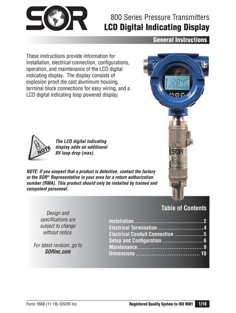
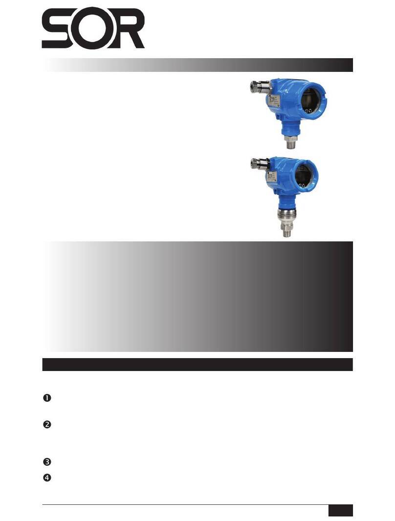
SOR echosonix U11 Instruction manual

Form 1186 (05.13) ©SOR Inc.
1/16
DISCONTINUED
U11 Loop Powered Transmitter
General Instructions
Registered Quality System to ISO 9001
Design and
specifications are
subject to change
without notice.
For latest revision, go to
www.sorinc.com
NOTE: If you suspect that a product is defective, contact the factory
or the SOR
®
Representative in your area for a return authorization
number (RMA). This product should only be installed by trained and competent personnel.
Table of Contents
Safety............................................ 2
Quick Start Installation Guide................ 2
Mounting the Transducer ..................... 4
Typical Mounting Guidelines................. 4
Installation on Solids ......................... 5
Wiring Instructions ............................ 6
Keypad Interface ............................... 7
LCD Display..................................... 8
Field Programming ............................ 9
User Dened Values..........................10
Menu Structure................................12
Dimensions ....................................14
Specications .................................16
Troubleshooting ...............................16
The U11 is a non-contact ultrasonic level-sensing device that operates from loop power. It
provides the following features for easier customer installation and operation:
n
Rugged, industrial design with cast aluminum explosion proof housing
n
Easy to use, plain English menus
n
All values entered in engineering units
n
4-20mA signal may easily be reversed to 20-4mA
n
Actual 4 and 20mA endpoints may be fine tuned
n
Choice of echo types – first, last and largest
n
Automated echo recognition for minor false echoes
n
Bin mapping to eliminate major false echoes
These instructions provide information for mounting, process
and electrical connections and field programming of the U11 loop
powered ultrasonic transmitter. The U11 incorporates a transducer
for sending and receiving an ultrasonic signal and an electronics
processing package. The ultrasonic signal is very powerful and may
cause hearing damage – refer to the safety instructions on page 2.
The electronics package is mounted on top of the transducer via a
permanent mechanical connection.

2/16
Form 1186 (05.13) ©SOR Inc.
DISCONTINUED
Switch and Switch Chamber Installation
Safety
Prior to installation, review these instructions entirely. Transducer mounting location is
critical to proper operation. Most settings can be programmed prior to installation.
Electrical Safety
The U11 is an electrically powered transmitter. Common electrical safety procedures must
be followed when working with this equipment. All wiring should be per local and national
standards. Do not open the cover on an energized unit in an explosion proof atmosphere.
Do not handle circuit boards when energized.
Sound Protection
The U11 produces intense sound pulses. SOR recommends checking local safety
standards for applicable hearing protection regulation.
Do not aim the transducer of an operating U11 at anyone’s head. Permanent hearing
damage may result. Use proper hearing protection when using in an enclosed space.
Electrostatic Discharge (ESD) Handling Procedure
Our electronic instruments are designed to the highest quality standards. These products
use highly sensitive electronic components that are affected by static electricity, which is
present in most work environments. The following procedure is recommended to reduce
the possibility of component failure caused by static electricity damage.
n
Use a grounded wrist strap when installing or removing electronic boards. A grounded
workstation is recommended.
n
Ensure that all electrical connections are made and none are partial or floating. Ground
all equipment properly.
Quick Start Installation Guide
Install the transducer away from obstructions. It should not be mounted in the center of
domed or conical roof tanks. See page 4 for minimum mounting distance from tank walls.
1/3 Vessel Radius 1/3 Vessel Radius
Inlet Pipe

Form 1186 (05.13) ©SOR Inc.
3/16
DISCONTINUED
23 - 30 VDC
Power Supply
250Ω to 750Ω
Loop
Resistor
Blanking
(No detection)
4 or 20mA
(High Level)
Distance
(In Echo EL feature)
4 or 20mA
(Low Level)
Emptdst
(Farthest valid echo)
Low Level
0%
High Level
100%
Wire the unit according to local and national safety codes. Power and
signal wiring must be run as a minimum. Refer to page 6 for
more wiring details.
NOTE: All values measured
and entered as a distance
from the top down.
Determine the values to be entered when programming the unit.
Calculate all high and low levels as the distance from the transducer
down to the target point.
Program the basic parameters in the Setup menu. Press CAL to access the Setup Menu.
See page 8 for details of the LCD display menu items and customer values.
NOTE: To change number values fast, hold down the arrow key.
Return to normal operation
Enter menus, change menu
selection, accept changes
Change numeric values and move between menu options
{
Distance
12.34 ft.
DistanceDistance
12.34 .12.34 .
cal run

4/16
Form 1186 (05.13) ©SOR Inc.
DISCONTINUED
Typical Mounting Guidelines
The transducer may be mounted using either a flange or the standard 3” NPT fitting.
Whether the unit is mounted on a flange or by threads, and whether it has a focusing cone
option or not, the end of the transducer assembly should always be mounted past the end
of the process connection assembly. The figures below illustrate proper mounting.
Minimum Mounting Distance
The transducer should be mounted so that the primary cone of
sound does not intersect the wall of the vessel. For best perfor-
mance the transducer should be mounted outside the “Minimum
Mounting Distance” shown below. When this is not possible,
consult the factory for recommendations. If the distance to the
sidewall is less than the “Minimum Mounting Distance” then
the unit may not be able to track the process properly.
Nozzle Mount Stand Pipe Mount
2” (50 mm)
Flush Mount Threaded Mount
Mounting the Transducer
Inlet Pipe
Enclosed Vessels
Tank geometry must be considered when mounting the transducer.
Certain types of vessels may create secondary echoes if the
transducer is not mounted correctly. The problem is primarily
with spherical vessels. This shape can refocus spent echoes
and cause false readings. Mounting the transducer in a
location that minimizes this effect can eliminate the problem.
Mount transducer away from
inlets and obstructions
Transducer mounting is critical. The transducer assembly both generates the sound pulse
and monitors the echoes. The ultrasonic pulses travel away from the face of the transducer
in a cone-shaped pattern. This area should be
free of obstructions and away from inlets.
The assembly should be in a position that
allows unobstructed access between
the transducer face and the process
to be measured.
Minimum
Mounting
Distance
1/3 Vessel1/3 Vessel
RadiusRadius

Form 1186 (05.13) ©SOR Inc.
5/16
DISCONTINUED
For vessels taller than 40 feet (12m), use:
Minimum Distance = Vessel Height X 0.087
Minimum Mounting Distance
3 feet
(0.9 m)
4 feet
(1.2 m)
2 feet
(0.6 m)
1 feet
(0.3 m)
10 feet
(3 m)
20 feet
(6 m)
40 feet
(12 m)
30 feet
(9 m)
Minimum Mounting Distance
Vessel Height
Installation on Solids
The U11 is able to reliably read solids from any angle of repose and through dusty condi-
tions. The transducer should be mounted in a vertical position according to the guidelines
below. SOR does not recommend aiming the transducer unless absolutely required for the
process, or special measurement is required as seen below.
In solids applications the transducer is typically mounted 1/3 of the distance from the wall
of the vessel to its center. As solids pile up they form a cone. Mounting the transducer in
the position shown below gives a rough average of what the level would be if the surface
were flattened out. This is true for both conical piles and pits (created when material is
drawn from the bottom).
1 2
3 3
Inlet Pipe
Inlet Pipe
Mount the transducer 1/3 of the vessel
radius in from the wall. Mount away from
inlet pipes, ladders, or other intrusions
that may create false echoes.
Transducer should be mounted vertical
pointing down towards the process.
The transducer needs to be aimed at the outfeed if level measurement
is required to the bottom of the vessel. The user must be aware that the
measured distance will be longer than the actual distance to the process
level due to the angle of aiming.
This mounting only holds true for round, cylindrical vessels
with a center inlet. In other shape vessels or where the inlet
is offset the transducer should be mounted according to the
user’s requirements.

6/16
Form 1186 (05.13) ©SOR Inc.
DISCONTINUED
Wiring Instructions
The U11 transmitter is powered by a 24VDC loop circuit. The most common method of
powering the unit is from a self-powered DCS/PLC card.
The U11 is an electrically powered transmitter. Common electrical safety
procedures must be followed when working with this equipment. All wiring
should be per local and national standards. Do not open the cover on an
energized unit in an explosive atmosphere. Do not handle circuit boards
when energized.
23 - 30 VDC
Loop Powered
Supply
250 to 750Ω
Resistor
Socket for
power cable to
display board
Wire
release
levers
Remove the display board by removing the three screws around its outer perimeter.
DO NOT remove the four screws at the corners of the LCD display. Move the display
out of the way.
String the wires through the electrical connections and seal connections properly.
Attach wires by pressing down on the small plastic lever while pushing the bare wire
end into the terminal socket.
Wiring Diagram
The terminal block positions are labeled per the diagram below. Polarity must be observed
when wiring the U11.

Form 1186 (05.13) ©SOR Inc.
7/16
DISCONTINUED
Keypad Interface
The U11 does not require calibration, but is does require customer setup for each
installation. The units, display type, high and low levels must be set as a minimum. Other
parameters may be required or desired for your specific application. See Menu Structure
on pages 12 & 13 for detailed descriptions of parameter setup.
All setup is done through the four-button display panel. The diagram below shows the
buttons and describes their function. The display panel also includes an indicator light for
the sensing pulse to verify operation of the unit.
NOTE: When changing numerical values, hold down the arrow button to make the value
change faster. The longer the button is held, the faster the value will change. Release the
arrow button and press again to return to normal rate of change.
Factory
test port
RUN button
used to exit
menus and
return to
normal
operation
CAL button
used to enter menus
and select/save menu choices
UP and DOWN
arrow buttons
used to move
between menu options
and change values
Pulse indicator light LCD Display

8/16
Form 1186 (05.13) ©SOR Inc.
DISCONTINUED
LevelLevel
26.83f26.83f
LevelLevel
28,70f28,70f
EngUnitsEngUnits
FeetFeet
Gn 9%Gn 9%
26.8026.80
LCD Display
Normal Operation
In normal operation the top line of the LCD shows the Material Display Mode selected in
the menu setup - Space or Material %. The second line displays the actual level status. The
unit can always be returned to normal operation by pressing the RUN button.
Normal Operation screen - display type on top line,
level reading on bottom line.
When the decimal changes to a comma,
the U11 has lost echo and is trying to recover it.
Programming Mode
In programming mode the top line of the display indicates what feature is being pro-
grammed. The bottom line shows the current choice for that feature. Move from feature to
feature using the arrow keys and press CAL to select and change that feature.
Programming feature shown on top line, user choices/values
shown on bottom line.
Troubleshooting Mode
When the unit is in normal operation, troubleshooting information is displayed by pressing
the up arrow key. The top line of the LCD changes to the troubleshooting information, the
lower line continues to display the level reading.
Troubleshooting data displayed on top line, level reading on
bottom line.
Every U11 comes with 2-line 16-character LCD display. This serves as a display of process
level and an interface for setting up the unit. There are three LCD display modes: normal
operation, troubleshooting and programming.
INDICATOR MEANING
. (Decimal) Normal operation
, (Comma) Recover mode – echo lost
: (Colon) Hold Mode – false echo found
outside of window

Form 1186 (05.13) ©SOR Inc.
9/16
DISCONTINUED
“CAL” Button
The CAL button is used to enter the menus and select menu options to
change. Press CAL from normal operation to enter the password screen.
Enter the password using the arrow keys (factory default is 0) and press CAL
to go to the menus. When the proper menu item is selected using the arrow
buttons, press CAL again to access that feature and make changes.
Field Programming
The U11 menus are accessible through the four-button keypad on the display board.
Information is displayed on the 2-line LCD, with the program feature shown on the top line
and the current setting displayed on the bottom line. All button functions are consistent for
all models and menus.
Units in Hazardous Locations – Prior to programming, make sure that the
work area is declassied before removing the explosion proof cover to
program the unit. Failure to do so could result in severe personal injury or
substantial property damage.
The and arrow buttons are used to change user values
and move between menu items. When changing numeric values,
hold the arrow button down and the values will change faster
the longer it is held. When the button is released and pressed
again the numbers will change at a slower rate.
cal
run
“RUN” Button
The RUN button returns the unit to normal operation mode. This button will
exit the menus at any point, saving the current selected options and entering
normal operation using all changes made in the menus.

10/16
Form 1186 (05.13) ©SOR Inc.
DISCONTINUED
User Dened Values
Several user-defined values must be entered for each application. The figure on page 11
illustrates these values and how they should be determined. It is important to remember
that all distance values are measured from the sensor down.
Blanking Every ultrasonic transmitter has a dead zone near the transducer where it cannot
measure level. In the U11 this is called the Blanking. The blanking is normally automatic
but may be set to a specific value if required for the application. If the user defined blanking
is shorter than the distance required by the automatic blanking, the U11 defaults to the
automatic value.
4 or 20mA Endpoints The range of the U11 is determined by setting the distance from the
transducer to the 4 and 20mA endpoints. An output of 20-4mA can be obtained by setting
the 4mA point at the top and the 20mA point at the bottom. These values are entered in
engineering units (feet or meters).
Distance The Echo Elimination* feature requires a Distance value to be entered. This is
the maximum distance to eliminate false echoes. When used, this value should be set
slightly higher than the low level of the process so that it does not eliminate the bottom
of the range. *USE THIS FEATURE ONLY WHEN REQUIRED!
Empty Distance (EmpyDst) The empty distance defines the farthest echo the U11 will
accept. This eliminates the possibility of reading a secondary echo that appears to be below
the bottom of the vessel. The Emptdst value should be set slightly farther than the end of
the measured range so it will not blank out the bottom of the process.

Form 1186 (05.13) ©SOR Inc.
11/16
DISCONTINUED
Blanking
(no detection)
4 or 20mA
(High Level)
High Level
100%
Distance*
(In Echo EL feature)
Low Level
0%
4 or 20mA
(Low Level)
Emptdst
(Farthest valid echo)
NOTE: All values are measured and entered as a distance from the top down

12/16
Form 1186 (05.13) ©SOR Inc.
DISCONTINUED
Normal
operation
screen.
Use the arrows at
this screen to enter
the unlock code
setup in screen N
below. The factory default is 0.
Use the arrows at this screen to change between the “Setup” and “Trim” menu. The Trim menu is
used to fine-tune the 4 and 20mA endpoints, temperature compensation adjustment, add an offset
or adjust the blanking if required.
Select the engineering units for level measurement on
the LCD display.
Select the display mode. Material shows level up from
the low end of 4-20mA range. % Matl shows the per-
cent of the 4-20mA range. Space shows distance from
the sensor face to the process media.
Set the distance from the sensor face for the 4mA point
of the range. This can be either the low or high level.
*Maximum value is determined by the sensor range.
USE THIS FEATURE ONLY WHEN REQUIRED!!
Set the distance from the sensor face for the 20mA point
of the range. This can be either the high or low level.
*Maximum value is determined by the sensor range.
This allows elimination of unwanted echoes. When false
echoes are present, use the following procedure:
Select CLEAR and press CAL to clear any current
settings.
Lower the process level below all unwanted echoes.
Select SET to find and eliminate unwanted echoes,
press CAL. The screen will display DISTANCE -
enter a distance value slightly less than the current
distance from the transducer face to the process
material, press CAL.
The display will say STORE? N; use the up arrow to
change to Y and press CAL. If you want to discon-
tinue mapping, press CAL while the screen says N.
The screen will say MAPPING and run through a
map routine. When complete, it will automatically
return to RUN mode and begin searching for the
process level.
Dist Offst CAL Dist Offst 0.00 ft.
to 16.00 ft. CAL
Dist 20mA CAL Dist 20mA
1.49 f
0.00 ft
to 25.00 ft.* CAL
Dist 4mA CAL Dist 4mA
12.85 f
25.00 ft*
to 0.00 ft. CAL
Display CAL Display
Distance % Level
Level CAL
Eng Units CAL Eng Units
Feet Metres CAL
Echo Elim CAL Echo Elim Clear Display
Manual Set CAL
Menu Structure
This is used to offset the output and display by the
entered distance. The offset must be included as part
of the maximum range.
Damping slows the output
reaction by averaging the level change over the time
period selected.
1 = 1 second 4 = 40 second 7 = 10.4 min.
2 = 5 second 5 = 1.7 min. 8 = 21 min.
3 = 12 sec. 6 = 4.2 min. 9 = 42 min.
DISTANCE
4.83 ft.
CAL
PASSWORD
0
CAL
Setup
CAL
The U11 is programmed through the keypad buttons. CAL is used to
enter the menus, access the options and accept the choices made.
RUN is used to exit the menus and enter run mode. The “
” and
“
q
” arrows are used to move between menu items and options.
When using the arrow buttons to change numerical values, hold it
down to make the numbers change faster.
Damping CAL Damping 0 to 9 CAL

Form 1186 (05.13) ©SOR Inc.
13/16
DISCONTINUED
Select how fast the process is expected to move. Select
a setting faster than the likely maximum rate.
1 = 0.3 ft./min. 3 = 1.5 ft./min. 5 = 9 ft./min.
2 = 0.6 ft./min. 4 = 4 ft./min. 6 = 16 ft./min.
Fail Safe time is how long the unit will search
after loss of echo before entering Fail Safe Mode.
1 = 23 sec. 4= 1.5 min. 7 = 2.5 min.
2 = 46 sec. 5 = 2 min. 8 = 3 min.
3 = 1.2 min. 6 = 2.3 min.
Select the desired output if the unit enters the Fail Safe
Mode. Last LVL (last level) maintains the output at the
time the unit enters Fail Safe.
The preferred echo type can be the First to cross the
threshold (prompted when First is chosen), the Last
to cross the threshold or the Largest of all echoes
detected. When First is chosen, a threshold value can
be entered. This value is used as a value to augment
the first echo. Example: 0% threshold = 100% echo
size; 10% threshold = 110% echo size.
The D Factor compensates for differences in sound
velocity in vapor mediums other than air. The default of
1.00 is for air (compensated for temperature).
D Factor = actual distance
displayed distance
The empty distance is the farthest distance the unit
should accept an echo from. This should be set slightly
larger than the low level value.
Enter a lock code to prevent unauthorized access to the
program menus. 0 is the factory default.
Press the CAL button to switch from “Setup” menu to “Trim” menu.
Press the RUN button to return to normal operation.
RUN
CAL
DISTANCE
4.83 ft.
Menu
Blanking CAL Blanking
0.43f
0.00f to
Empty Dst CAL
Trk Speed CAL Trk Speed
41 to 6 CAL
FSafe Tim CAL FSafe Tim
31 to 8 CAL
FSafe Opt CAL FSafe Opt
<20.00mA
20.00mA
4.00mA
Last LVL
<4.00mA
>20.00mA
CAL
Echo Type CAL Echo Type
First
First
Last
Largest CAL
Dst Factr CAL Dst Factr
1.00 0.67
to 1.50 CAL
Empty Dst CAL Empty Dst
59.00f Low Level to
59.00 ft. CAL
Password CAL Password
00 to 999 CAL

14/16
Form 1186 (05.13) ©SOR Inc.
DISCONTINUED
Dimensions
Integral Electronics
30 kHz Transducer
FC Option
Dimensions are for reference only.
Contact the factory for certified drawings
for a particular model number.
Linear = mm/inches
Drawing 0390629

Form 1186 (05.13) ©SOR Inc.
15/16
DISCONTINUED
Integral Electronics
20 kHz Transducer
FC Option
Linear = mm/inches
Drawing 0390630

16/16
Form 1186 (05.13) ©SOR Inc.
DISCONTINUED
14685 West 105th Street, Lenexa, KS 66215
n
913-888-2630
n
800-676-6794 USA
n
Fax 913-888-0767
Registered Quality System to ISO 9001
Printed in USA sorinc.com
When the unit is in normal operation, several diagnostic features can be accessed by
pressing the button. The top line of the display will scroll through two items detailed here
as the button is pushed. The bottom line of the display will continue to show the normal
output. Accessing the diagnostic feature will not affect analog or relay outputs.
Datum Description
GN Gain being currently applied to the received echo. (Includes GR below.)
E The actual distance currently being detected, regardless of damping or
window location.
Troubleshooting
Specications
Electronics
Input Voltage......................................................................................................23 to 30 VDC
Input Source .............................................................................................2-wire, loop power
Electronic Accuracy..................................................................... +0.25% of maximum range
Maximum Value for Loop Resistor.............................................................................. (750Ω)
Display.........................................................................2 x 8 digit alpha/numeric LCD display
Memory ..................................................................Nonvolatile (no backup battery required)
Transmitter Operating Temperature........................................... -4oF to 140oF (-20oC to 60oC)
Display Operating Temperature................................................ 14oFto 140oF (-10oC to 60oC)
Enclosure Material ......................................................................................... Cast Aluminum
Frequency Blanking Distance Liquid/Slurry Range Solids Range Standard Mounting
30 kHz 12” (0.3m) 33 ft. (10m) N/A 3” NPT
Table of contents
Other SOR Transmitter manuals
Popular Transmitter manuals by other brands
Kramer
Kramer TP-594Txr quick start guide
Linear
Linear 2 GIG 2GIG-Z-BRDG-433 Install instructions
National Wireless
National Wireless Securetek ST-100 Series Installation and User Instruction

Evikon
Evikon PluraSens E2638-VOC user manual
Endress+Hauser
Endress+Hauser Liquisys CUM 252 operating instructions
TKH security
TKH security VBS 2020 TX-3 user manual
