Soredex DIGORA Optime DXR-50 001 User manual

DIGORA®Optime DXR-50 001
Digital intraoral imaging plate system
User’s Manual
Document no. 204253 rev. 2 (0908)
EN


User’s manual 204253 I
Imaging plate unit
DIGORA®Optime DXR-50 001
Digital intraoral imaging plate system
User’s Manual
This unit is marked according to the Medical Device Directive
93/42/EEC (if the unit contains the CE mark)
Document number 204253 rev. 2 (0908)
Original approved English language version
Manufactured by SOREDEX
P. O. B OX 1 4 8
FIN-04301 TUUSULA,
FINLAND
Tel. +358 (0)10 270 2000
Fax. + 358 9 701 5261

II User’s manual 204253
Imaging plate unit
Soredex endeavours to produce product documentation that is accurate and up
to date. However, our policy of continual product development may result in
changes to products that are not reflected in the product documentation. There-
fore, this document should not be regarded as an infallible guide to current
product specifications. Soredex maintains the right to make changes and
alterations without prior notice.

User’s manual 204253 III
Imaging plate unit
Contents
1. The DIGORA® Optime.................................................................... 1
1.1 Introduction .................................................................................................. 1
1.2 System installation....................................................................................... 2
Positioning the unit ................................................................................... 2
Positioning the PC .................................................................................... 3
Other devices ........................................................................................... 3
2. Intraoral imaging plate unit ............................................................... 4
2.1 Main parts and controls ............................................................................... 4
2.2 Accessories ................................................................................................ 5
2.2 Display symbols and what they mean ........................................................... 7
2.3 Using the system ....................................................................................... 10
Preparing the system .............................................................................. 10
Preparing an IP for exposure ...................................................................11
Imaging plate holders .............................................................................. 13
Taking an exp osure ................................................................................. 14
Reading an imaging plate ....................................................................... 16
Single user configuration ............................................................................................ 16
Multiconnect configuration ......................................................................................... 19
Removing IPs from the plate collector ..................................................... 20
Standby mode ........................................................................................ 20
Retrieve last image ................................................................................. 21
Shutting down the unit ............................................................................. 22
IP erasing mode (Initial erasing of the IPs)............................................... 22
Errors ..................................................................................................... 23

IV User’s manual 204253
Imaging plate unit
3. Setup options ................................................................................. 24
3.1 Tooth numbering ........................................................................................ 24
Selecting the tooth numbering feature ..................................................... 24
Using the tooth numbering feature ........................................................... 24
3.2 Resolution ................................................................................................. 25
3.3 Image Processing ..................................................................................... 25
4. Handling and care of imaging plates.............................................. 26
4.1 General ..................................................................................................... 26
4.2 Handling .................................................................................................... 26
4.3 Cleaning.................................................................................................... 27
4.4 Storage ..................................................................................................... 28
4.5 Replacement ............................................................................................. 28
4.5 Disposal .................................................................................................... 28
5. Unit care and maintenance............................................................. 29
5.1 Cleaning the unit ........................................................................................ 29
5.2 Disinfecting unit ......................................................................................... 29
5.3 Maintenance.............................................................................................. 30
5.4 Repair ....................................................................................................... 30
5.5 Disposal .................................................................................................... 30
6. Symbols that appear on or in the unit............................................. 31
7. Warnings and precations ............................................................... 32
Appendix A. Technical Specifications ............................................ A - 1
Appendix B. Installation and setup ................................................. B -1

User’s manual 204253 1
Introduction Imaging plate unit
1. The DIGORA®Optime
1.1 Introduction
This manual describes how to use the DIGORA®
Optime digital imaging plate unit (the unit) which is
part of the digital intraoral imaging plate system (the
system). The complete system comprises the
following:
-the DIGORA
® Optime digital imaging plate unit
(the unit).
-SOREDEX dental Imaging Plates (IPs),
protective covers, hygiene bags and other related
imaging plate accessories.
-A PC (not supplied) in which suitable dental
imaging software.
-A local area network (LAN) cable (not supplied)
will be required if the system is to be used in a
network.
The unit is a laser scanning device designed to
automatically read reusable SOREDEX dental
intraoral imaging plate sizes 0, 1, 2, and 3. After
reading the images can be viewed on the PC using
the dental imaging sofware.
The unit can either be connection directly to the PC or
to network via the LAN cable.
The unit can be set up to work with a single PC, the
single user configuration, or with several PCs, the
multiconnect (multiple user) configuration.
With the multiconnect configuration up to eight PCs
can be used, one at a time, with the unit. This manual
describes how to use both configurations.

2 User’s manual 204253
Imaging plate unit Introduction
NOTES:
Only personnel trained and authorized by the
manufacturer of the unit are allowed to install and
configure the unit.
Only use the imaging plates, protective covers and
hygiene bags supplied by the manufacturer of the unit.
Please read the section 7. Warnings and
precations before using the unit.
1.2 System installation
Positioning the unit
Do not position the unit in direct sunlight or near bright
light. Sunlight or bright light must not be allowed to
shine directly on the unit door into which the IPs are
inserted.
Position the unit on a stable flat surface so that
vibrations will not degrade the image quality.
The unit can also be attached to a wall, under or on a
shelf with the optional mounting kit.
The unit must not be positioned so that it it touching
other equipment. It must not be placed on top of or
under other equipment.
The unit can be positioned within the environment in
which the patient is examined and treated (patient
environment).

User’s manual 204253 3
Introduction Imaging plate unit
Positioning the PC
The PC connected to the unit should not be used in
the patient environment.
The minimum horizontal distance between the patient
and the PC is 1.5 m (4.5 ft).
The minimum vertical distance between the patient
and the PC is 2.5 m (6.5 ft).
Other devices
DO NOT connect any other devices to the unit or the
PC connected to the unit that are:
-not part of the supplied system
-not supplied by the manufacturer of the unit
-not recommended by the manufacturer of the unit.

4User’s manual 204253
Imaging plate unit 2. Intraoral imaging plate unit
2. Intraoral imaging plate unit
2.1 Main parts and controls
User’s manual 204253 5
2. Intraoral imaging plate unit Imaging plate unit
2.2 Accessories
For additional information about the accessories
listed below contact your authorized dealer. Not all
accessories are available for all units.
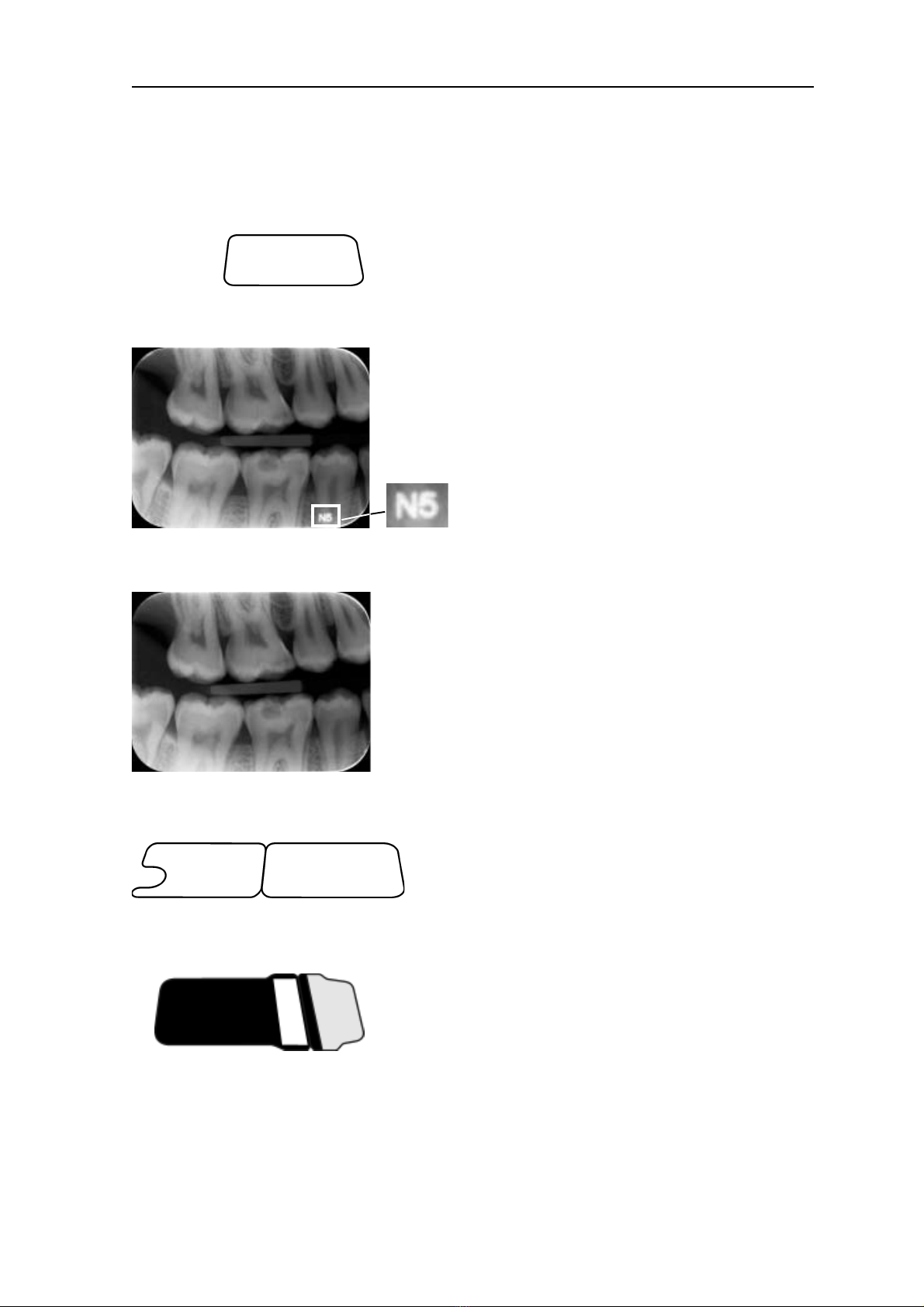
Imaging plates (IPs). Equivalent to film sizes 0, 1, 2
and 3.
IDOT version. An identification code (IDOT) is printed
on the IP and will appear on the intraoral image. The
IDOT identification mark allows the IP used for an
exposure to be easily identified and removed if it
damaged.
Standard (STD) version. The standard version has no
identification mark.
Protective covers. For IPs 0, 1, 2 and 3.
Hygiene bags. For IPs 0, 1, 2 and 3.
6User’s manual 204253
Imaging plate unit 2. Intraoral imaging plate unit
CAUTION:
For optimum performance only use IPs, protective
covers and hygiene bags supplied by the
manufacturer of the unit or the manufacturer’s
authorized distributors.
The manufacturer will not be held responsible for
problems caused by using accessories from other
manufacturers.
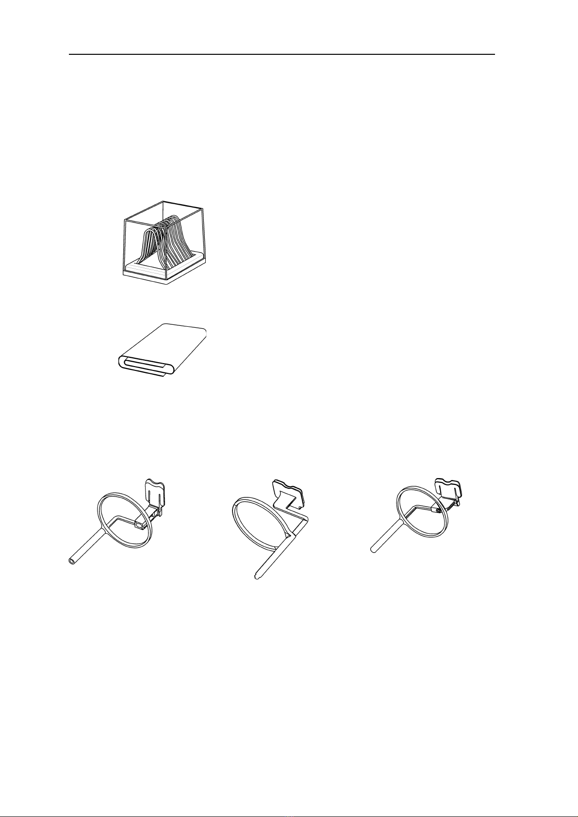
IP storage box
For storing IPs safely and conveniently
Microfiber cloth
For cleaning IPs
IP holders
For bitewing, periapical and endodontic exposures
(optional, not included)
See section Imaging plate holders for more
information.

User’s manual 204253 7
2. Intraoral imaging plate unit Imaging plate unit
2.2 Display symbols and what they mean
During use symbols and animations will appear on
the unit display. These:
-indicate the status of the unit
-help you to operate the unit correctly
-show user mistakes and corrective actions
-display error codes
-display a preview image
The main symbols are:
Startup
During startup the unit serial number, IP address and
other information will appear on the unit display.
Multiconnect wait
Multiconnect configuration. The unit is not reserved by
any PC in the system.
Multiconnect reservation
Multiconnect configuration. The unit has been
reserved by a PC (e.g. PC number 2).
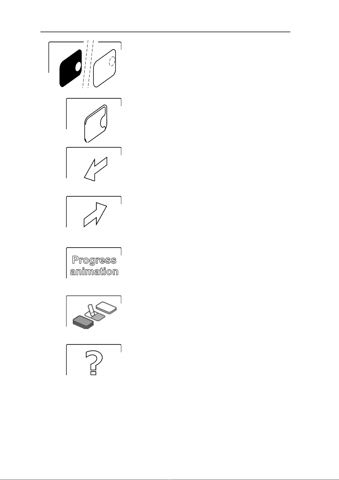
Unit door
Protective cover and imaging plate
Yellow: remove protective cover
8User’s manual 204253
Imaging plate unit 2. Intraoral imaging plate unit
Imaging plate
Yellow: wrong way round, rotate
Protective cover
Remove / disconnect
Insert / connect
Busy
Unit in operation.
Unit in erasing mode
Check
Something wrong or take alternative action.

User’s manual 204253 9
2. Intraoral imaging plate unit Imaging plate unit
Dental imaging software
Software not open, not ready or waiting for user
action.
Unit connection
Not connected or connection not working.
Rotate
Error state and error number
Check documentation supplied with the unit
Unit in service mode
(Service technicians only)

10 User’s manual 204253
Imaging plate unit 2. Intraoral imaging plate unit
2.3 Using the system
For optimum performance only use IPs, protective
covers and hygiene bags designed for this unit and
supplied by authorized distributors.
The manufacturer of this unit will not be held
responsible for any problems caused by using
accessories from other manufacturers.
Proper handling, cleaning and storage of the IPs
ensures the best image quality and maximum service
life of the IPs. Refer to section 4. Handling and care
of imaging plates.
Preparing the system
1. PC: Switch on the PC connected to the unit.
2. PC: Open the dental imaging software and a new
or existing patient card where you wish to store
the intraoral images.
NOTE:
If you are using the system for the first time you
may wish to check and / or change the setup
options. See section 3. Setup options.
3. Press the on/off key to switch the unit on.
The startup animation will appear on the display
and the unit will carry out self test during which the
IP carrier will slide out of the unit door.
User’s manual 204253 11
2. Intraoral imaging plate unit Imaging plate unit
When the status light turns green and ready
animation, indicating IP insertion, appears on the
unit display, the unit is ready to use (in the ready
state).
NOTE:
If the ready animation does not appear, check the
system setup described in the installation
instructions.
Preparing an IP for exposure
IMPORTANT NOTE
If the IP is being used for the very first time or if it has
not been used within the the last 24 hours, it must be
erased before use to remove any fogging caused by
background radiation. See section, Erasing an
imaging plate.
CAUTION:
When handling IPs, protective covers and hygiene
bags take all appropriate measures and precautions
to prevent cross contamination.
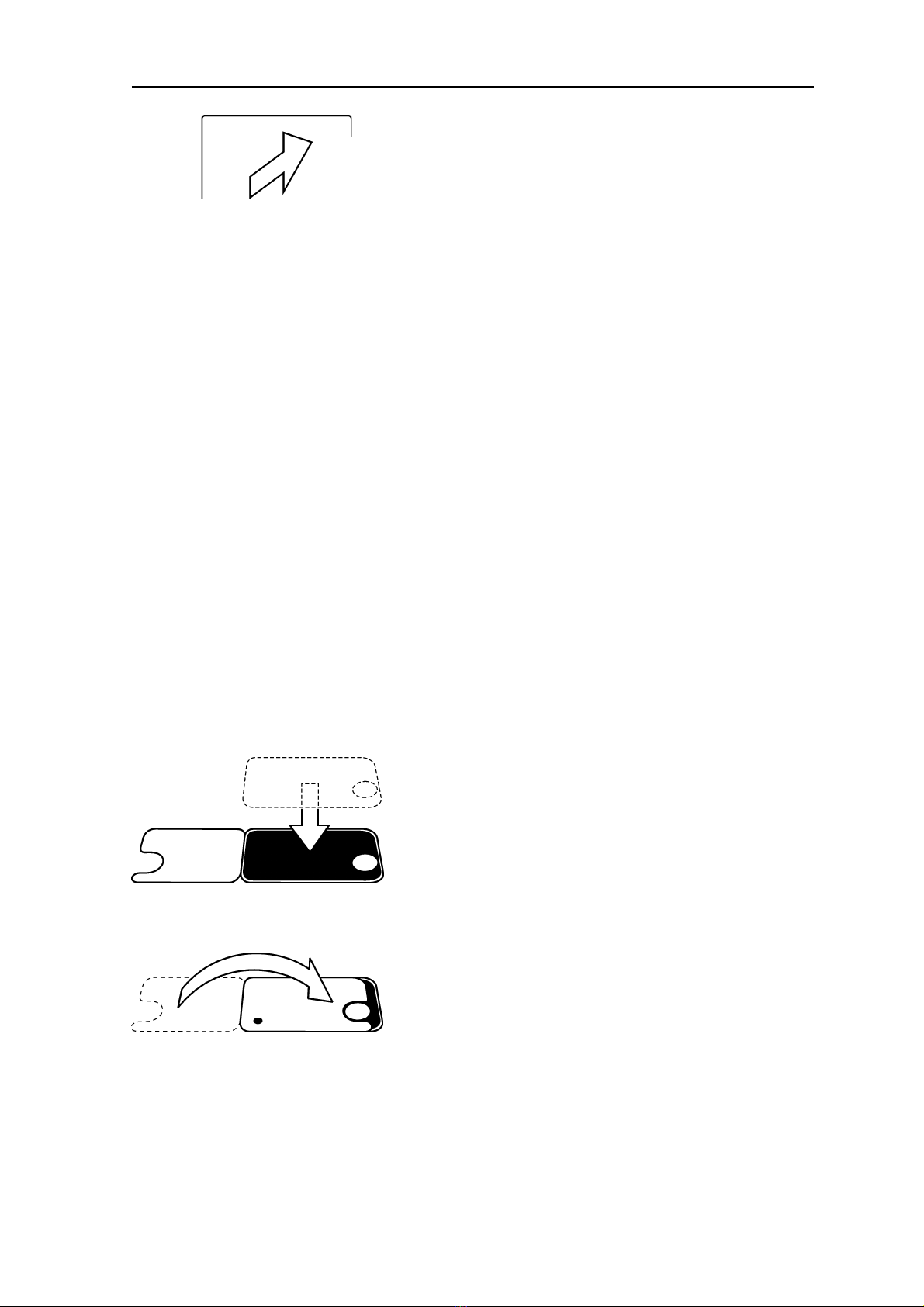
1. Place the IP you wish to use onto a protective
cover. The light blue side (sensitive) of the IP
must face and be placed on the half of the
protective cover that is the same shape as the IP.
2. Fold the half of the protective cover with the
semicircular cutout over onto the IP. The metal
disk on the back (black side) of the IP must
appear in the semicircular cut out.

12 User’s manual 204253
Imaging plate unit 2. Intraoral imaging plate unit
3. Turn the protective cover and IP over so that the
black side of the protective cover is uppermost.
This makes it easier to slide the protective cover
and IP into the hygiene bag.
4. Slide the protective cover and IP into the hygiene
bag as far as they will go. Make sure that the
black side of the protective cover is on the same
side as the black side of the hygiene bag.
5. Peel off the cover paper from the sealing tape and
then fold the flap, along the pre-formed line, over
and onto the sealing tape.
6. Press and slide your thumb along the tape to
ensure that the flap is properly sealed.
7. Turn the sealed hygiene bag over and check that
the IP and protective cover are in the correct
position.
You must be able to see the light side of the
protective cover and the metal disk on the IP.

User’s manual 204253 13
2. Intraoral imaging plate unit Imaging plate unit
Imaging plate holders
It is recommended that imaging plate holders be used
to ensure accurate IP positing and consistently good
images quality.
Using imaging plate holders improves image quality
because:
-the IP is positioned correctly in relation to the tooth
-there is no positioning guesswork
-the IP is not bent and thus distortion is eliminated
-the IP cannot move in relation to the X-ray unit
-images are standardized and reproduceable
-there is no overlapping nor cone cut off
-IP wear and tear is minimized
-image quality can be maintained irrespecective of
who takes the image
-time is saved and profitability increased
Problems caused by manually positioning the IP
include:
-incorrect vertical alignment
-distortion
-cone cut off
-poor projection standardization
-inferior image quality
For more information on imaging plate holders and
systems contact you dealer.
14 User’s manual 204253
Imaging plate unit 2. Intraoral imaging plate unit
7uj7uj7
Taking an exposure
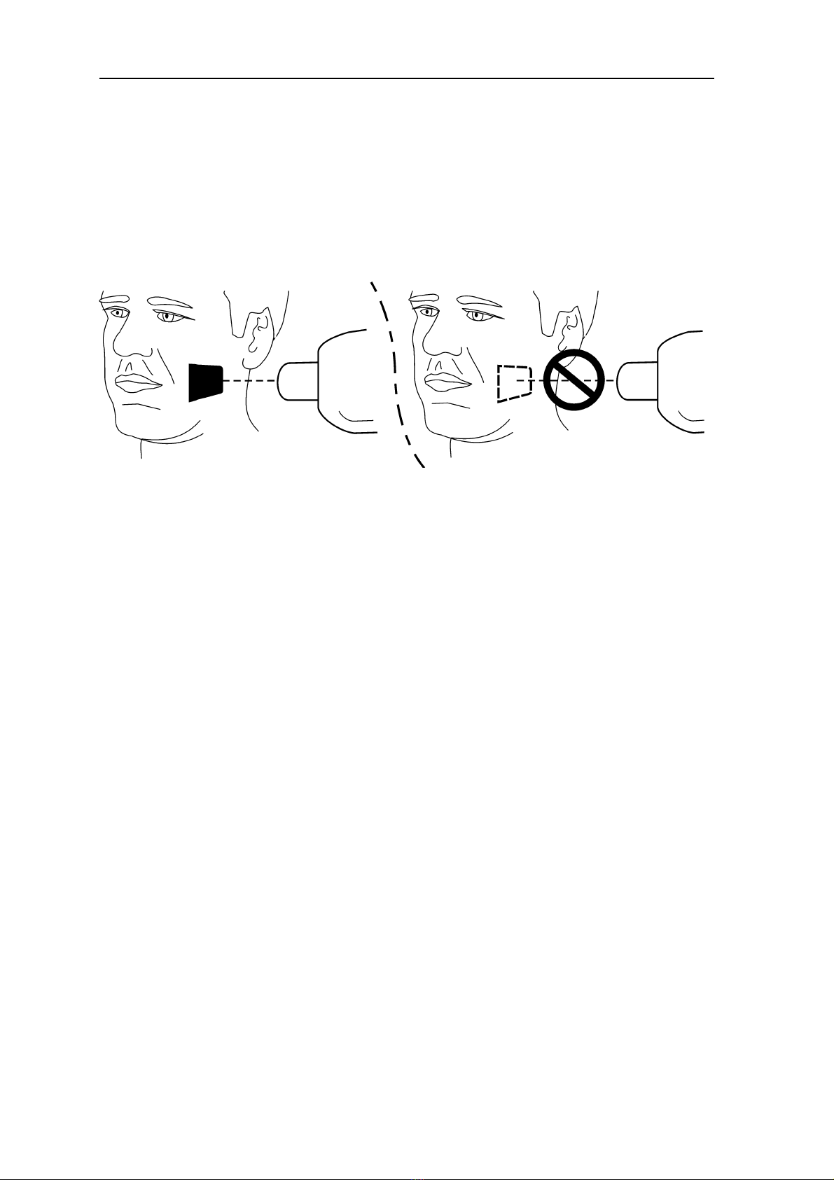
1. Place the IP, in its sealed hygiene bag, into the
appropriate imaging plate holder and then insert it
into the patient’s mouth in the position for the
image you wish to take.
Note that the back of the sealed hygiene bag, the
black side, must face the X-ray source.
2. Select exposure values appropriate for the
exposure you are taking.
The system will produce excellent images even if
the exposure values differ considerably from the
optimum values. In most cases the same
exposure values can be used for virtually all
imaging purposes.
For normal everyday use select the Adult
Bitewing exposure time from the following table.
If required the exposure time can be increased for
very large patients and reduced for children.
The optimium exposure values also depends on
the performace of the X-ray unit being used and
may vary by ±1 step from the values in the
following table.
Other manuals for DIGORA Optime DXR-50 001
1
Table of contents
Other Soredex Medical Equipment manuals


Popular Medical Equipment manuals by other brands


KYRA MEDICAL
KYRA MEDICAL KYRA Comfort KYRA3000 Instructions for use

Harvest Healthcare
Harvest Healthcare BUMPERS General User/ Safety Guide

Ethicon
Ethicon ECHELON FLEX Steps for Use

NSE
NSE UV Series user manual

Air Techniques
Air Techniques PERI-PRO III user manual

Nasco
Nasco Lifeform LF01121U instruction manual