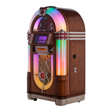
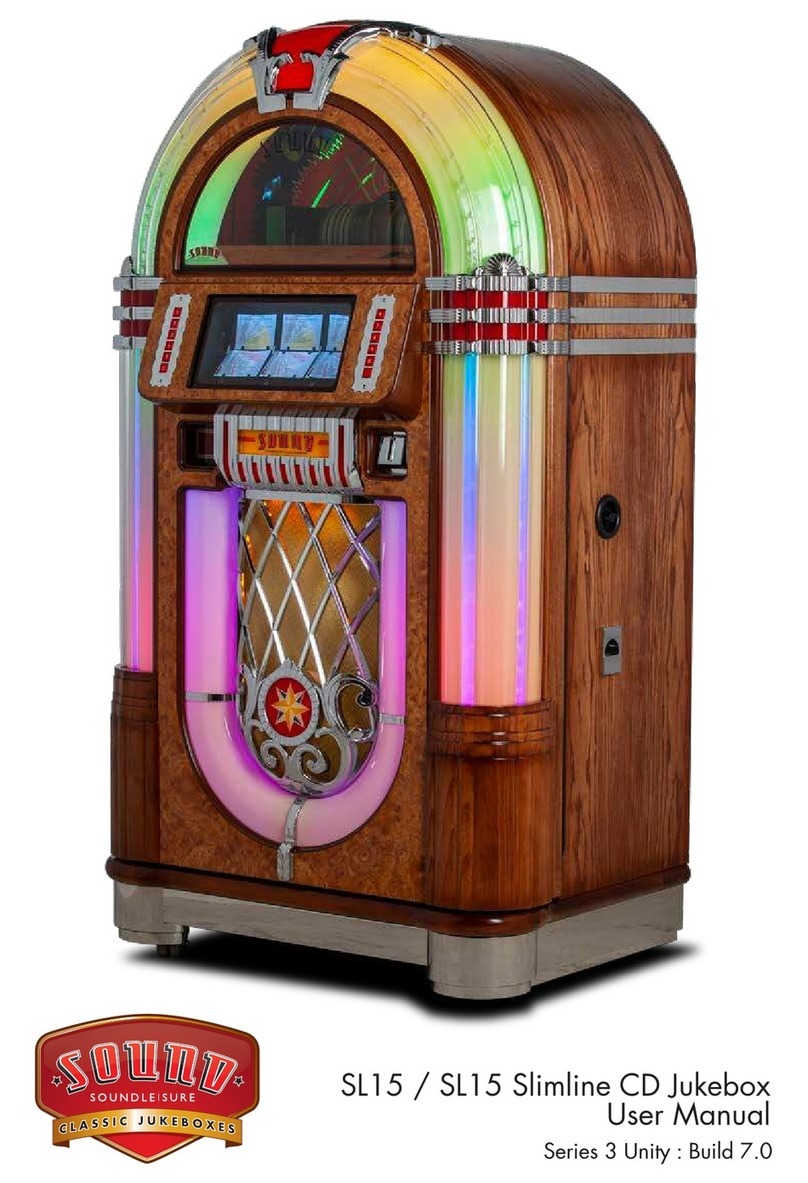
Sound Leisure Mini Jook User manual

SOUND LEISURE LTD.
39 INGS ROAD, LEEDS, LS9 9EW,YORKSHIRE,
ENGLAND
TEL:0113 2175000 FAX:0113 2175003
WWW.SOUND-LEISURE.COM
Email: tech@soundl.force9.uk
Version 3

CONTENTS
Page No.
1. Introduction .................... .......... .......... ......... ................1
2. System Features............. .......... .......... ......... ................1
3. Installation Requirements......... .......... ......... ................2
3.1 Minijook.................. .......... .......... ......... ................2
3.2 Wallbox.................. .......... .......... ......... ................3
3.3 System Connection Details.......... ......... ................ 3
3.4 Cable Requirements......... .......... ......... ................3
3.5 Meters.................... .......... .......... ......... ................5
3.5.1 Series 3 Wallbox...... .......... ......... ................5
3.5.2 Series 2 Wallbox...... .......... ......... ................5
3.5.3 MiniJook board ACS1067 .. ......... ................5
3.6 Installation of Compact Discs....... ......... ................5
3.7 Selection Display.... .......... .......... ......... ................6
3.8 Making a Selection. .......... .......... ......... ................6
3.9 Specification........... .......... .......... ......... ................6
3.10 Lights .................... .......... .......... ......... ................6
3.11 Motors.................... .......... .......... ......... ................6
3.12 Fuses .................... .......... .......... ......... ................7
3.13 System Reset......... .......... .......... ......... ................7
4. Important Notes ............. .......... .......... ......... ................8
4.1 Compact Disc Care .......... .......... ......... ................ 8
5. MK6 Mono Sound System......... .......... ......... ................ 8
5.1 Warnings................ .......... .......... ......... ................ 9
5.2 MK6 Pre Amplifier.. .......... .......... ......... ................ 9
5.3 MK6 Power Amplifier......... .......... ......... ................ 10
5.4 MK6 Slave Amplifier Output......... ......... ................ 10
5.5 Karaoke ................. .......... .......... ......... ................ 11
5.6 Back Ground Music .......... .......... ......... ................ 11
5.7 Input Connection.... .......... .......... ......... ................ 12
5.8 Controls ................. .......... .......... ......... ................ 13
6. Dil Switch Settings ......... .......... .......... ......... ................ 14
7. Programming ................. .......... .......... ......... ................ 15
7.1 Menu Structure ...... .......... .......... ......... ................ 15
7.2 Moving through Levels...... .......... ......... ................ 16
7.3 Editing a Menu....... .......... .......... ......... ................ 16
7.4 Exiting a Menu ....... .......... .......... ......... ................ 17
7.5 Menu Format.......... .......... .......... ......... ................ 18
Menu 1......(Plays)........ .......... ......... ................ 18
Menu 2......(Coins) ....... .......... ......... ................ 18
Menu 3......(Bonus Plays)........ ......... ................ 19
Menu 4......(Bonus Plays)........ ......... ................ 20
Menu 5......Factory Settings.... ......... ................ 20
Menu 6......Day,Date,Year ...... ......... ................ 21
Menu 7......Hours,Minutes....... ......... ................ 22
Menu 8......Timer1........ .......... ......... ................ 22
Menu 9......Timer2........ .......... ......... ................ 23
Menu 0......Random Time ....... ......... ................ 23
7.6 Exiting Programme Mode.. .......... ......... ................ 23
8. Free Credit ....... ........ .......... .......... ......... ................ 24
9. Popularity ........ ........ .......... .......... ......... ................ 25
10. Sequence Of Operation.. .......... .......... ......... ................ 26


- Page 1 -
1. INTRODUCTION
This manual contains information on the Sound Leisure equipment designed around the
'System 5' type of electronics.
Although the information in this manual was correct at the time of printing, the
manufacturer reserves the right to make changes, without prior notice.
The contents of this manual may not be copied in part or full without prior consent from
Sound Leisure Ltd.
2. SYSTEM FEATURES
30 Disc Capacity
Up to 900 Track Selections
Adjustable Consecutive Track Plays
Selections Played in Selected Order
Adjustable B.G.M. Disc Band
Automatic Music Fade
Programmable Price of Play
Popularity Data Retrieval
Mechanical Cash Meter Facility under Software Control
Microphone Input with Separate Volume, Treble & Bass, and Voice Over
Activation
Auxiliary Line Input Socket
600 Ohm Slave Output Point with Gain Preset
2 Individual Timers
Adjustable Foreground Disc Band
7 Day 24 Hour Real Time Clock
Individual Start and Stop Times for Timer1 and Timer2
Week Days, Weekends, or Every Day Enable for Each Timer
Manual Enable for B.G.M Operation
Programmable Random Play from 1 to 99 Minutes

- Page 2 -
3. INSTALLATION REQUIREMENTS
After unpacking the equipment, the following guide should assist you in achieving a
trouble free installation.
3.1 MINIJOOK
Place the Minijook in the position in which it will be finally installed.
Ensure the location is dry and the equipment is set level.
There must be a mains supply socket within two metres of the equipment.
Measure the mains supply to ensure it is 230V a.c. If the supply is less than
the recommended voltage level stated please contact your local generating
board for advice.
We recommend an earth continuity test is carried out on the mains supply socket
prior to use.
Unscrew the two transit securing bolts located one at each side of the play
mechanism. These bolts should be unscrewed and withdrawn complete.
NOTE: We would like to bring to your attention that, since 1992, portable
appliance testing is required and a certificate of compliance issued.
3.2 WALLBOX
Firmly affix the wallbox hanging bracket so that on completion the coin input slot
is at a height that can be reached with ease.
The wallbox, once hung on the bracket, is anchored with two bolts.
~~~~~~~~~~~~~~~~~~~~~~~~~~~~~~~~~~~~~~~~~~~~~~~~~~~~~~~~~~~~~~~~~~~
The holes in the wallbox are oversized to facilitate its levelling.

- Page 3 -
3.3 SYSTEM CONNECTION
There are three wallbox connectors in the jukebox/hideaway system each having
five terminals. These are located on a small circuit board labelled: 'Wall Box
Distribution Board' as shown below.
A
B
3
2
1
A
B
3
2
1
WALLBOX DISTRIBUTION BOARD
2A2A2A
MPU Wb1 Wb2 Wb3
A
B
3
2
1
C2
R1 VR1
D1 D2
3.15A
3.15A 14V
14V
0V
+5V
0V
PAGE
MOTOR
PAGE Sw1 PAGE Sw2
Page motor wiring for
units without a
SLE 101A Board fitted
Power line cables on
Terminals 1+3
Signal cables on
Terminals A and B
Each wallbox should be individually wired back to the jukebox/hideaway
unit.
3.4 CABLE REQUIREMENTS
The connection between individual wallboxes and a jukebox/hideaway
unit is done via five cables as shown above.
Connectors are located within each piece of equipment. These
connectors have terminals labelled 1, 2, 3, A and B.
Connect 1 to 1, 2 to 2, 3 to 3, A to A and B to B.
Cables connected to terminals 1 and 3 must have a minimum conductor
diameter of 1mm (0.75mm² cross sectional area) when connecting wallboxes up
to 50meters away and 1.5mm diameter (1.5mm² cross sectional area) when the
wallbox is up to 100meters away.
Terminals 1 and 3 handle the wallbox low voltage supply. The power is supplied
by the hideaway/jukebox as 14-0-14V a.c.
Terminal 2 is the common ground return.

- Page 4 -
Terminals 'A' and 'B' are used for data transmission, with 'A' for data
transmission from the jukebox/hideaway unit and 'B' for data transmission from
the wallbox.
These two cables are signal lines and are not required to handle any great power
therefore much lighter gauge wire may be used.
Note: A minimum of 25V a.c. should be measured across terminals 1
and 3 at each wallbox to avoid any power supply problems.

- Page 5 -
3.5 METERS
A 12V d.c. meter without internal diode may be connected to any C.D.
wallbox or any minijook.
N.B. Such meters are not polarised and can be connected either way around.
3.5.1 SERIES 3 WALLBOX
Connect the meter to the two pin plug labelled MTR/CON5
on the ACS1043 board.
3.5.2 SERIES 2 WALLBOX
Locate the sentinel coin interface board. A meter may be
connected to the two pin plug located on this board.
3.5.3 MINIJOOK BOARD (ACS1067)
Connect the meter to the two pin plug labelled METER on
the ACS1067 board.
3.6 INSTALLATION OF COMPACT DISCS
When standing in front of the C.D. play mechanism place the C.D's onto
the stack with the picture face on top and the clear face underneath.
PICTURE
SIDE
DATA
SIDE
ONE COMPACT DISC VIEWED IN STACK
CD STACK LEVEL

- Page 6 -
3.7 SELECTION DISPLAY
The selection display flashes between a three digit number and a two digit
number.
The three digit number identifies the last disc selected and the two digit number
identifies the track played on that disc.
3.8 MAKING A SELECTION
Five numbers need to be entered via the keypad to make one selection.
The CD mechanism can hold a maximum of 30 discs.
Each disc location is identified by a three digit number i.e. 100 to 129.
Example: To select a disc in location 125 enter the three digit number which
identifies that disc, i.e. 125.
Having entered the disc number you now need to enter a two digit
number for the track you wish to play from that disc.
The track number must be in the range: 01 to 30.
3.9 SPECIFICATION
Dimensions (Minijook)
Height 790mm
Width 700mm
Depth 265mm
Weight 50Kg
3.10 LIGHTS
1 x 12" Fluorescent tube
3.11 MOTORS
Disc Clamp Arm Motor 12V d.c.
Left/Right Motor 12V d.c.
CD Lift Motor 1.8 Degree Stepper

- Page 7 -
3.12 FUSES
ACS1067 Board
F1 1 x 3.15A Slow Blow Amplifier Fuse
F2 1 x 3.15A Slow Blow Amplifier Fuse
F3 1 x 3.15A Slow Blow Stepper Motor
Cabinet
2 x 10 Amp Used For a.c. Supply 14-0-4V a.c.
1 x 500mA Used For Laser Player Power Supply
1 x 2.5A Slow Blow Used For Mains Power
Speaker Matching Pad
2 x 2.5A Slow Blow
Wall Box Distribution Board
2 x 2.5A Slow Blow
3.13 SYSTEM RESET
For a system reset press and hold REJECT and CREDIT BUTTONS on ACS1067
board and turn machine ON at mains. Keep held until tower has travelled all the way
to bottom of mechanism. The credit table will be zeroed.

- Page 8 -
4. IMPORTANT NOTES
4.1 COMPACT DISC CARE
The signal read out surface is the reverse side of the printed label side. The
compact disc is fairly resistant to scratches and dirt but it is best to be careful not
to scratch the signal surface and to keep it clean - free from dust, dirt and
fingerprints.
Disc Cleaning
If the signal surface becomes dirty, use the following for cleaning compact
discs:-
When cleaning use a soft cloth. Wipe the cloth from the centre of the disc to the
edge of the disc until the complete signal surface is clean. Do not clean the disc
in a circular motion as this can corrupt large amounts of information.
a) Fingerprints Lightly rub the surface with a soft cloth.
b) Dust or Dirt Blow lightly on the disc and wipe the dirty part with a
soft cloth or clean the dirty part with a damp soft cloth
and then wipe dry.
c) Grease or Oil Clean with a soft cloth dampened with Ethyl Alcohol,
then wipe dry.
N.B. Conventional liquids and sprays used to clean records may damage the
surface of the disc. Use of such a cleaner is not recommended.
Also, please do not expose the disc to direct sunlight, heat or humidity for
prolonged periods of time.
Ensure both sides of the compact disc are damage free. It is important
to note that damage to picture side as well as the read side of the disc
can result in corrupt data.

- Page 9 -
5. MK6 MONO SOUND SYSTEM
5.1 WARNINGS
5.1.1 Damage to the sound fader circuit on the ACS1067 Board may occur
if the amplifier is unplugged whilst the machine is switched on.
5.1.2 The Sound Leisure MK6 amplifier is not suitable for connection to a
100V line system.
5.2 MK6 PRE-AMPLIFIER
INPUTS Three 5-pin, 180oDin sockets.
Input 1 CD This input has priority and auto-fade control over input 2.
The two stereo inputs are first combined into one mono
signal before being split into two channels each with pre-set:
gain, bass and treble controls.
Input 2 Auxiliary (Aux)
BGM auto-fade approximately 45 seconds after last track
played.
Input 3 Microphone (Mic)
The Mic input has auto-fade control priority with precedence
over inputs 1 and 2. In addition, preset gain along with
independent bass and treble controls are provided.
N.B. Line Input level assumed to be: 2V p/p or 0.7071 RMS.
Also: the microphone should be a low impedance type (600 ohm).
VOLUME CONTROLS
Independent control of each channel is possible via a dual 22k log slider remote
volume control (R.V.C.).
The R.V.C. circuit is of the D.C. type and may be run over long distances without
the use of screened cable.

- Page 10 -
5.3 MK6 POWER AMPLIFIER
Frequency Range 15hz to 20khz with flat response.
Load impedance 4ohms minimum.
Power output 60W R.M.S. per channel into 4ohms.
The power output stage is overload protected.
5.4 MK6 SLAVE AMPLIFIER OUTPUT
The slave amplifier output is taken from Pin T3 on the pre-amp board. The
signal return (ground) for the slave amplifier can be picked up on the amplifier
chassis of the MK6 amplifier. The slave output signal is controlled via the
potentiometer VR12, on the pre-amplifier board.
The slave output voltage is in the range: 600mV to 3V peak-to-peak.
NOTE:
When fitting a Sound Leisure slave amplifier it is necessary to upgrade
the amplifier power supply fuses from 3.15A to 6A.
These fuses are located on the main ACS1067 MPU board.

- Page 11 -
5.5 KARAOKE
The facility of karaoke can be accomplished by lifting one end of resistor
R71 on the MK6 pre-amplifier top board.
This disables the voice over function of the microphone.
(See page 13 for the location of R71)
5.6. BACK GROUND MUSIC (BGM)
Sound Leisure offers two ways to use BGM.
1. Timed
2. Constant
CONSTANT BGM
Constant BGM is achieved by a switch/link across pins (10 to 14) on the ACS1067 plug
PL15.
When the switch is closed the jukebox will play BGM on a permanent basis until the
switch is opened again. The discs selected for BGM will be the band of discs previously
programmed into Menu 5 at levels 3 and 4.
SWITCH/LINK
14 10 1
PL15

- Page 12 -
5.7 INPUT CONNECTIONS
(INPUT STEREO)
VIEWED LOOKING AT FRONT FACE OF FIVE-PIN DIN PLUGS.
SIDE VIEW OF AMPLIFIER
(OUTPUT DUAL
CHANNEL MONO OR
STEREO)
111
222
333
444
555
AUXILLARYMICRO-PHONE JUKEBOX / CD
MIC in
p
ut
(
sensitivit
y
1
)
MIC in
p
ut
(
sensitivit
y
2
)
LEFT
CHANNEL RIGHT
CHANNEL RIGHT
CHANNEL
LEFT
CHANNEL

- Page 13 -
5.8 CONTROLS
EXTERNAL VOLUME CONTROL CONNECTIONS VIA MAIN M.P.U.
4 WAY RIBBON CABLE
CONNECTS TO JUKEBOX M.P.U.
Yellow
Green Brown
Q1
VR1
CH II PRESET
R 71
CH II
TREBLE
CH I
TREBLE
MIC
TREBLE
B
A
S
S
B
A
S
S
B
A
S
S
C11
CH I
CH I
AUX
VOLUME
CONTROL
VOLUME
CONTROLS
VOLUME
CONTROL
AGC CONTROL.
DO NOT ADJUST
(LEAVE TURNED FULLY
CLOCKWISE)
JUKEBOX / CD
INPUT
AUXILIARY
INPUT
MICROPHONE
INPUT
SLAVE OUTPUT
600 mV / 600 OHMs
MIC
VR 12
SLAVE OUTPUT CONTROL
ACW
T3
T4
(600/600) OHM
ISOLATION TRANSFORMER
SS
FF TO AUX AMP
SYSTEM
GROUND
FULLY ANTI CLOCKWISE
SLAVE OUTPUT = 600mV
FULLY CLOCKWISE
SLAVE OUTPUT = 3 V
White

- Page 14 -
6. DIL SWITCH SETTINGS
DIP SW 1 BANK 1
Mechanism setting in conjunction with display. Turn ON at mains with DIP SW1 ON.
The left digit of display indicates if the Sync Opto is blocked or clear.
The display will show '0' if Opto is clear or '1' if the Opto is blocked.
The right hand digit shows button pressed.
Button '1' energises phase '1' on stepper motor.
Button '2' energises phase '2' on stepper motor.
Button '3' energises phase '3' on stepper motor.
Button '4' energises phase '4' on stepper motor.
Button '5' & '6' open and close clamp arm.
Button '7' & '8' moves pick up arm up and down one position.
Button '9' & '0' moves transfer arm in and out.
To exit this routine turn the mains OFF, return DIP SW1 to OFF position and turn the
mains back ON.
DIP SW 2 Stepper motor speed ON = FAST, OFF = SLOW.
DIP SW 3
When DIL SW3 is on, and the service switch is in the OFF position the least played disc
will be automatically fetched from the stack by the pickup arm.
Remove the least played disc from the pickup arm and replace with the new disk.
Pressing CANCEL on the selection keypad to return the new disc to the stack.
When this process is complete the second least played disc will be automatically
fetched from the stack and presented for exchange. This process will continue,
presenting discs within the stack in descending order of popularity until all discs have
been exchanged. This process can be exited at any time by switching the machine
'OFF' then 'ON' with service switch in the operate position.
This will automatically reset the popularity table.
DIL SW 4 Permanent random play.
DIL SW 5 Not Used.
DIL SW 6 Count skips on bad discs.
DIL SW 7 Allows programming credit table when set to ON position in service mode.
DIL SW 8 Permanently free credit.
N.B. DIL SW 3 has priority over DIL SW 7.

- Page 15 -
7. PROGRAMMING
PROGRAMMING WALLBOX ONLY.
When entering into the program mode the following two steps must be carried out:-
1. Turn the service switch located on front right hand side of minijook cabinet to the
'UP' position.
2. Turn on SW 7 on one wallbox only.
Also ensure SW 7 on DIL 1 switch bank is turned on.
This is located on the ACS1067 board.
PROGRAMMING MINIJOOK ONLY.
1. Set the service switch located on the front right hand side of the minijook cabinet to
the 'UP' position.
2. Turn on SW 7 on DIL 1 switch bank.
This is located on the ACS1067 board.
Once the machine has entered the program mode it responds by displaying two zeros
as shown below:
00
Ten menus may be entered, each menu being four levels deep.
7.1 MENU STRUCTURE
N.B. The first five menus are illustrated below.
MENU 1
PLAYS MENU 2
COINS MENU 3
BONUS
PLAYS
MENU 4
BONUS
COINS
MENU 5
FACTORY
DEFAULT
LEVEL 1
LEVEL 2
LEVEL 3
LEVEL 4

- Page 16 -
When the display shows two zeros, any menu may be entered. This is achieved
by pressing the menu number (0-9).
The menu number entered will be displayed in between the two zeros,
Example
Menu 2 selected
020
When a menu number is pressed it will be displayed for a short while before the
display changes to show the contents of the first level in the menu, thus:
1
Level number Data locations for level 1
7.2 MOVING THROUGH LEVELS
Levels can be stepped through by pressing the level numbers (1-4).
7.3 EDITING MENU
Assuming you are in the correct menu and level, follow the steps below:-
Step 1: Press 'C' key to overwrite old data.
(The central and right-hand displays will blank)
Step 2: Enter new data.
Step 3: Press 'C' key to lock new data into memory.
Table of contents
Other Sound Leisure Jukebox manuals

Sound Leisure
Sound Leisure Vinyl Beat User manual

Sound Leisure
Sound Leisure 1015 User manual

Sound Leisure
Sound Leisure SL33 User manual

Sound Leisure
Sound Leisure Rocket User manual

Sound Leisure
Sound Leisure SL15 User manual

Sound Leisure
Sound Leisure vinyl rocket User manual

Sound Leisure
Sound Leisure VINYL POP User manual

Sound Leisure
Sound Leisure Classic LONG PLAYER User manual

Sound Leisure
Sound Leisure VenueHub User manual

Sound Leisure
Sound Leisure Gazelle User manual