Spaceman 6224 User manual

OPERATOR’S
MANUAL
Model: 6224
www.spaceman-company.com

Table of Contents
Section1 To the installer ----------------------------------------------------- 1
Air Cooled Units -------------------------------------------------------------------- 1
Electrical Hook-Up Installation For 220V/ 50Hz/ 1Ph,
Supplied With Cord and Plug --------------------------------------------------- 1
Specification ------------------------------------------------------------------------ 1
Section2 To the Operator -------------------------------------------------- 3
Section3 Safety ---------------------------------------------------------------- 4
Section4 Installation Instructions ----------------------------------------- 5
Section5 Important: Operating Control ------------------------------- 8
Indicator Light-“Mix Low” --------------------------------------------------------- 8
Fluorescent Display------------------------------------------------------------------ 8
Power ON/OFF Switch ------------------------------------------------------------- 8
Symbol Definitions ----------------------------------------------------------------- 9
Operating Descriptions-------------------------------------------------------------- 9
Reset Button -------------------------------------------------------------------------- 9
Wash Button -------------------------------------------------------------------------- 10
Cool Button --------------------------------------------------------------------------- 10
Standby Button ---------------------------------------------------------------------- 11
Ice Cream Button ------------------------------------------------------------------- 12
P Button ------------------------------------------------------------------------------- 12
Set Menu ------------------------------------------------------------------------------ 12
Fault Description -------------------------------------------------------------------- 14
Section6 Operating Procedures ---------------------------------------- 17
Assembly ----------------------------------------------------------------------------- 17
Sanitizing ----------------------------------------------------------------------------- 19
Priming ------------------------------------------------------------------------------ 19
Closing procedure ---------------------------------------------------------------- 20
Draining product from the freezing cylinder --------------------------------- 20
Rinsing ------------------------------------------------------------------------------- 21
Cleaning ----------------------------------------------------------------------------- 21
Disassembly ------------------------------------------------------------------------ 22
Brush cleaning --------------------------------------------------------------------- 22
Section7 Important: Operator Checklist ---------------------------- 24
During cleaning and sanitizing ------------------------------------------------- 24
Troubleshooting Bacterial Count --------------------------------------------- 24
Regular Maintenance Checks ------------------------------------------------ 25

Section8 Troubleshooting Guide --------------------------------------- 26
Section9 Electrical Drawing ---------------------------------------------- 28
Note: Continuing research results in steady improvements; therefore,
information in this manual is subject to change without notice.

Page 1
Section1 To the installer
Air Cooled Units
The model 6224 ice cream machine’s air cooling unit requires a minimum of 15.2cm of
clearance around both sides. Install the skirt provided on the right side of the unit and
place the back of the unit against a wall to prevent recirculation of warm air.
Electrical Hook-Up Installation for 220 Volt/ 50Hertz/ 1 Phase, Supplied With Cord
and Plug
This equipment is supplied with a 3-wire cord and grounding type plug for connection to
a single phase, 220 volt, 50 hertz, branch circuit supply. This unit must be plugged into
a properly grounded receptacle. The cord and plug provided for is 30 amp; therefore the
wall outlet must also be 30 amp. Check the data label, located in the side panel, for
electrical specifications. The plug should be accessible after installation.
If the supply cord is damaged, it must be replaced by the manufacturer, its service agent
or similarly qualified person in order to avoid a hazard.
Permanent wiring may be employed if required by local codes. Instructions for
conversion to permanent wiring are as follows:
1. Be sure the freezer is electrical disconnected.
2. Remove the appropriate panel and locate the small electrical box at the middle of the
freezer.
3. Remove the factory-installed cord and strain relief bushing.
4. Route incoming permanent wiring through hole in base pan.
5. Connect two power supply leads. Attach ground (earth) wire to the grounding lug
inside the electrical box.
6. Be sure the unit is properly grounded before applying power.
CAUTION: THIS EQUIPMENT MUST BE PROPERLY GROUNDED! FAILURE TO DO
SO CAN RESULT IN SEVERE PERSONAL INJURY FROM ELECTRICAL SHOCK!
SPECIFICATIONS
MODEL 6224
FLOOR MODEL,GRAVITY FREEZER
DIMENSIONS:
Freezer: 40.4cm wide ×74.3cm deep ×68.4cm high
Packing: 55.0cm wide ×77.0cm deep ×89.0cm high
WEIGHT
Freezer: 115kg Packing: 129kg
Page2
Section1 To the installer
ELECTRICAL:
Voltage AC: 1 Phase 200-240V 50 Hertz
Total Run Amps: 12 Amps
Drive Motors: 1.5 HP
Main Compressor: 3150 BTU/Hr.
(BTU may vary depending on compressor used.)
COOLING
Air-cooled required minimum 15.2cm air clearance around the freezer.
HOPPER
Two hoppers, 8 liters×2, refrigerated and insulated.
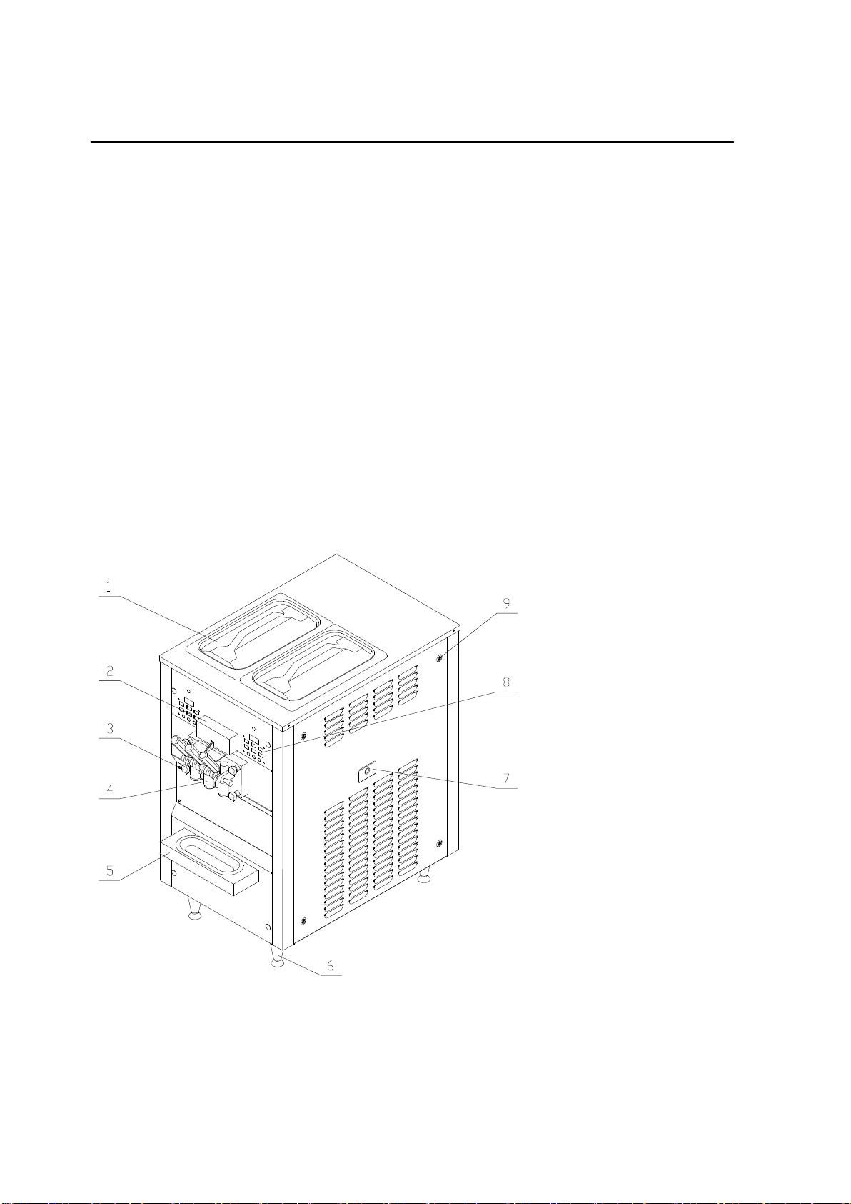
MACHINE VIEW
1.Top cover
2.Spigot switch cover
3.Dispensing door nut
4.Dispensing door
5.Drip pan
6.Leg-Plastic
7.Rear seal drip
8.Control Panel
9. Panel attaching lock

Page 3
Section2 To the Operator
The freezer you have purchased has been carefully engineered and manufactured to
give you dependable operation.
These units, when properly operated and cared for, will produce a consistent quality
product. Like all mechanical products, they will require cleaning and maintenance. A
minimum amount of care and attention is necessary if operating procedures outlined in
this manual are followed closely.
This Operator’s Manual should be read before operating or performing any maintenance
on your equipment.
The Models 6224 will NOT eventually compensate and correct for any errors during the
set-up or filling operations. Thus, the initial assembly and priming procedures are of
extreme importance. It is strongly recommended that personnel responsible for the
equipment’s operation, both assembly and disassembly, go through these procedures
together in order to be properly trained and to make sure that no misunderstandings
exist.
MIX INFORMATION
The hygiene ice cream powder is required to be used for frozen production. Mix can
vary considerably from one manufacturer to another. Differences in the type of
ingredients, quality, and quantity all have a different bearing on the finished frozen
product. A change in freezer performance that cannot be explained by a technical
problem may be related to mix. Mix does not improve with age. Old mix or mix that has
been stored at too high a temperature can result in a finished product that is less than
satisfactory from the appearance and taste standpoint.
Proper serving temperature varies from one manufacturer’s mix to another. Most mixes
should provide a satisfactory product in the –9℃to –5℃range. When checking the
temperature, stir the thermometer in the frozen product to read the true temperature.
Always maintain at least 2cm of mix in the hopper. The maximum of mix in the hopper
is 8 liters in one hopper.
In the event you should require technical assistance, please contact your local
authorized Distributor.

Page4
Section3 Safety
We at Spaceman Company are concerned about the safety of the operator when he or
she comes in contact with the freezer and its parts. Spaceman has gone to extreme
efforts to design and manufacture built-in safety features to protect both you and service
technician.
IMPORTANT- Failure to adhere to the following safety precautions may result in
severe personal injury. Failure to comply with these warnings may damage will
result in part replacement expense.
TO OPERATE SAFELY:
1. DO NOT operate the freezer without reading this operator’s manual. Failure to follow
this instruction may result in equipment damage, poor freezer performance, health
hazards, or personal injury.
2. DO NOT operate the freezer unless it is properly grounded. Failure to follow this
instruction may result in electrocution.
3. DO NOT allow untrained personnel to operate this machine. Failure to follow this
instruction may result in severe personal injury to fingers or hands from hazardous
moving parts.
4. DO NOT attempt any repairs unless the main power supply to the freezer has been
disconnected. Failure to follow this instruction may result in electrocution. Contact
your local authorized Spaceman Distributor for service.
5. DO NOT operate the freezer with larger fuses than specified on the freezer data label.
Failure to follow this instruction may result in electrocution or damage to the machine.
Consult your electrician.
6. DO NOT operate the freezer unless all service panels and access doors are
restrained with screws. Failure to follow this instruction may result in severe
personal injury from hazardous moving parts.
7. DO NOT obstruct air intake and discharge openings:
Minimum of 15.2cm of clearance around both sides. Install the skirt provided on the
right side of the unit and place the back of the unit against a wall to prevent
recirculation of warm air.
Failure to follow this instruction may cause poor freezer performance and damage to the
machine.
1. DO NOT put objects or fingers in door spout. Failure to follow this instruction may
result in contaminated product or personal injury from hazardous moving parts.
2. DO NOT remove the freezer door or beater assembly unless the control switches are
in the “OFF”position. Failure to follow this instruction may result in severe personal
injury from hazardous moving parts.

Page 5
Section4 Installation Instructions
Caution
Failure to install the freezer within recommended limits will result in poor
performance of this system, premature component failure and cancellation of the
warranty.
Installation of freezer involves moving the unit close to its permanent location, removing
all protective packaging, setting in place and cleaning.
A. Uncrate the freezer.
B. Raise the freezer, then draw out the pedestal.
C. The freezer required adequate ventilation. A minimum of 15.2cm of vent space is
required for free flow of cooling air.
D. Install the drip pan on the freezer (Figure 4-1).
E. Install the beater with the beater seal (Figure 4-2).
Insert the beater assembly with beater seal through the rear shell bearing at the back
of the cylinder evaporator and engage the hex end firmly into the female socket.
When properly seated, the beater will not protrude beyond the front of the cylinder
evaporator.
F. Install the dispensing door on the freezer (Figure 4-3, 4-4).
Figure 4-1
Figure 4-2
Figure 4-3
Figure 4-4

Page6
Section4 Installation Instructions
G. Install the standpipe into the hopper (Figure 4-5, 4-6).
H. Connect the power cord. Check the nameplate on the freezer for supply. The unit
must be connected to a properly grounded receptacle.
I. When connect the power supply and press on the ON/OFF switch, the fluorescent
display indicate:
J. Press STOP button, then press P button indicate temperature of cylinder and hopper.
IMPORTANT: If one or both of two temperature value(s) indicate(s) “00C”, you must STOP machine
and contact the authorized service technician to check the temperature sensor connection.
Caution
This Equipment Must Be Properly Grounded! Failure To Do So Can Result In
Severe Personal Injury From Electrical Shock!
PANEL REMOVAL:
To remove the panel, using a
flat head screwdriver into the
panel attaching lock.
Turn the lock in the direction
shown in Figure 4-7.
Figure 4-6
Figure 4-5
SPACEMAN
MODEL 6224
HOPPER TEM. 10C
CYCLINDER TEM. 10C
Figure 4-7
Page 7
3
1
R E S E T P
5
2
4
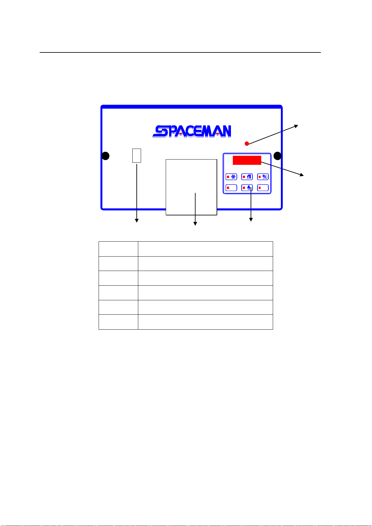
Section5 Important: Operating Control
Before operating the machine, it is required that the operator know the function of each
operating control. Refer to Figure 5-1 Figure 5-2 for location of the controls panel of the
machine. It is easy to activate and control all of the machine functions from the front
panel.
I
0
Indicator Led-”Mix Low”
When the led is “ON”, it indicates that the mix hopper has a low supply of mix and
should be refilled as soon as possible. Always maintain at least 2cm of mix in the
hopper. If you neglect to add mix, a freeze-up may occur. This will cause eventual
damage to the beater assembly, the dispensing door and gear box.
Fluorescent Display
During normal operation the display is used to indicate function, the temperature of the
mix in the hopper and cylinder, the electric current of beater motor, error and warning
messages.
Power ON/OFF Switch
Press “I”, control boards will get power from the main power source.
Item
Description
1
Indicator Led- "Mix Low"
2
Fluorescent Display
3
Touch Switch Panel
4
Spigot Switch Cover
5
Power ON/OFF Switch
Figure 5-1

Page8
Figure 5-2
Section5 Important: Operating Control
Symbol Definitions
To better communicate in the International arena, symbols have replaced words on many
of our operator switches. SPACEMAN equipment is designed with these International
symbols. The following chart identifies the symbol definitions.
1 2 3
4 5 6
Item
Description
1
COOL Button and Led
2
WASH Button and Led
3
STANDBY Button and Led
4
RESET Button
5
ICE CREAM Button and Led
6
P Button
Operating Descriptions
When connect the power supply, the fluorescent display indicate:
RESET BUTTON (Item 4)
Press RESET button to exit current mode, fluorescent display indicates STOP, date and
time. All function buttons are available. To change to other function, IT IS ALWAYS
NECESSARY to first press RESET button to return STOP.
P
RESET
SPACEMAN
MODEL 6224

Page 9
Section5 Important: Operating Control
WASH BUTTON (Item 2)
1. Press WASH button, the led of WASH comes “ON”. The beater motor operate,
fluorescent display indicates “WASHING”.
2. Press P button, the fluorescent display indicates:
Indicate present temperature of mix in hopper.
Indicate present temperature of mix in cylinder.
3. Press P button once again, the fluorescent display indicates:
Indicate the electric current of beater motor.
Number before “/”is present electric current of beater motor.
Number after “/”is maximum electric current of beater motor been set.
4. Press P button once again, fluorescent display indicates “WASHING”. Press P button,
fluorescent display will cycle from step 2.
5. Press Reset button, the led of WASH comes “OFF”, fluorescent display indicates
STOP. All function buttons are available.
COOL BUTTON (Item 1)
1. Press the COOL button, the led of COOL comes “ON”. Fluorescent display indicates
“COOLING”. Beater motor and agitator start. Both refrigeration systems start. One
for cylinder to make product, the other for hopper to pre-cool mix and keep
temperature of mix in hopper under 4℃as default.
2. When temperature of mix in hopper falls 1 degree below 4℃, mix hopper refrigeration
system automatically stops. It automatically starts when temperature rises by 1℃
above 4℃.The default 4℃can be adjusted under SET MENU.
3. Refrigeration for cylinder runs until the unit cycles OFF, the product in the freezing
cylinder will be at serving viscosity. Raising the draw valve will activate the beater
motor and the product will flow out from under the door spout. The viscosity of
product is controlled by electric current of beater motor. The higher electric current
the higher the viscosity of product. The viscosity can be adjusted under SET
MENU.
4. Press P button, the fluorescent display indicates:
Indicate present temperature of mix in hopper.
Indicate present temperature of mix in cylinder.
HOPPER 0.0C
CYCLINDER 0.0C
CUR. 1.34 / 2.00 A
HOPPER 0.0C
CYCLINDER 0.0C

Page10
Section5 Important: Operating Control
5. Press P button once again, the fluorescent display indicates:
Indicate the electric current of beater motor.
Indicate the scale of viscosity.
When the second line is full by “*”, the product is at serving viscosity.
6. Press P button once again, fluorescent display indicates “COOLING”. Press P
button, fluorescent display will cycle from step 4.
7. Press Reset button, the led of COOL comes “OFF”, fluorescent display indicates
STOP. All function buttons are available.
STANDBY BUTTON (Item 3)
During long “No Sale” periods, the unit can be placed into the Standby mode. This
maintains product temperatures below 4°C in both the hopper and the freezing cylinder,
and helps prevent overbeating and product breakdown. You will save significantly on
energy consumption, as the compressor runs only for the time strictly necessary in order
to keep product at its correct temperature.
1. Press STANDBY button, the led of STANDBY comes “ON”. Fluorescent display
indicates:
2. Press P button, fluorescent display indicates:
Indicate current temperature of mix in hopper.
Indicate current temperature of mix in cylinder.
3. Indicate above menu for 5 seconds, fluorescent display will return to:
4. If no any button is pressed in 10 minutes, fluorescent display will enter save mode,
led of background will OFF. Till press any button except Reset button, led of
background will ON.
5. Press Reset button, the led of STANDBY comes “OFF”, fluorescent display indicates
STOP. All function buttons are available.
STANDBY
NOT DRAW
STANDBY
NOT DRAW
MOTOR 1.34 / 2.00 A
******************
HOPPER 0.0C
CYCLINDER 0.0C

Page 11
Section5 Important: Operating Control
ICE CREAM BUTTON (Item 5)
1. Press ICE CREAM button to check the number of servings dispensed from the
machine. The fluorescent display indicates:
Indicate the quantity of ice cream serviced today.
Indicate the quantity of ice cream serviced total
2. Indicate above menu for 5 seconds, fluorescent display will return to:
3. Press Reset button, fluorescent display indicates STOP. All function buttons are
available.
P BUTTON (Item 6)
1. At COOL and WASH mode, pressing P button will change the display menu between
temperature and electrical current.
2. At STANDBY mode, pressing P button indicate temperature for 5 seconds.
3. At STOP mode, pressing P button indicate temperature.
SET MENU
The SET Menu is used to enter the parameter setting. To access the Menu, press and
hold the RESET button for 3 seconds.
In the Menu program, the RESET, COOL, STANDBY, P, WASH and ICE CREAM button
will function as menu keys.
STANDBY BUTTON - increases the value above the cursor.
P BUTTON - decreases the value above the cursor.
RESET BUTTON - change screen of setting.
COOL BUTTON - change item of setting.
WASH BUTTON - not save the setting and exit.
ICE CREAM BUTTON - save the setting and exit.
1. At STOP mode, press and hold the RESET button for 3 seconds, fluorescent display
indicates:
- The above value is the maximum viscosity setting. When the electrical current
achieves the value, the product is at serving viscosity, stop the refrigeration of
cylinder. The higher electric current is higher viscosity of product.
Today: 00000
Total: 0000000
VISCOSITY SET
CURRENT: 2.00
HOPPER 0.0C
CYCLINDER 0.0C

Page12
Section5 Important: Operating Control
- Press the STANDBY button to increase the value.
- Press the P button to decrease the value.
2. Press RESET button once, fluorescent display indicates:
- In COOL and STANDBY cycle, machine will start to cool mix in hopper when
temperature of mix in hopper is 1 degree higher than above value. And stop it
when the temperature is 1 degree lower. In the STANDBY cycle, same function for
mix in cylinder.
- Press the STANDBY button to increase the value.
- Press the P button to decrease the value.
3. Press RESET button once, fluorescent display indicates:
- Set the date and time.
- Press the STANDBY button to increase the value. Press the P button to decrease
the value.
- Press COOL button to set next parameter.
- To save the changes on this screen, you must press and hold ICE CREAM button
for 3 seconds. After it is saved, the screen will jump out of the SET MENU
automatically. If press RESET button, this adjustment will NOT be saved.
4. Press RESET button once, fluorescent display indicates:
- Set the automatic program at set time.
- For example:
P: 1 08:00 start COOL mode at 08:00 every day.
P: 2 21:00 start WASH mode at 21:00 every day.
P: 3 22:00 start STANDBY mode at 22:00 every day.
- Press the STANDBY button to increase the value. Press the P button to decrease
the value.
- Press COOL button to set next parameter.
- P: 0 is no automatic program. There are 1 hour at least between COOL and other
program.
- To save the changes on this screen, you must press and hold ICE CREAM button
for 3 seconds. After it is saved, the screen will jump out of the SET MENU
automatically. If press RESET button, this adjustment will NOT be saved.
MIX TEMPERATURE
L SET: 4.5C
P: 0 00 : 00
P: 0 00 : 00
2011 /01 /16
14 : 47 :58

Page 13
Section5 Important: Operating Control
5. Press RESET button once, fluorescent display indicates:
- It is requirement of service set pass code
6. Press RESET button, fluorescent display will cycle from step 1.
7. If exit SET MENU not save setting, press WASH button, fluorescent display indicates:
8. If save setting and exit SET MENU, press and hold ICE CREAM button for 3 seconds,
fluorescent display indicates:
9. Press Reset button, fluorescent display indicates STOP. All function buttons are
available.
FAULT DESCRIPTION
Listed below are the variable fault messages which will appear, along with an explanation
for the corrective action.
If the machine has been stopped a long time due to a failure, it is necessary that you
check product temperature before starting the sale again; if the temperature is over +6°C,
the machine must be emptied, cleaned and sanitized, and filled up with new fresh mix.
1. In the course of any mode, press P button indicate temperature of cylinder and hopper.
IMPORTANT: If one or both of two temperature value(s) indicate(s) “00C”without any
change for more 2 minutes, you must STOP machine and contact the authorized
service technician to check the temperature sensor.
STOP
SAVE OK
STOP
NOT SAVE
ENTER CODE
0 0 0 0
HOPPER 0.0C
CYCLINDER 0.0C

Page14
Section5 Important: Operating Control
2. In COOLING cycle, if fluorescent display appears:
The temperature of cylinder achieves or lower than the lowest temperature setting.
The led of COOL and STANDBY will be sparked, compressor stop, beater motor
working.
Press RESET button, fluorescent display indicates STOP.
Lower viscosity setting in SET MENU item1 or contact the authorized service
technician to check lower the temperature of cylinder protection setting
Press the WASH button and observe the machine's performance.
If the beater motor is turning properly, press the RESET button.
Press COOL button to resume normal operation.
If no any button is pressed in 10 minutes, machine will enter STANDBY mode
automatically.
3. In COOLING cycle, if fluorescent display appears:
The electrical current of beater motor achieves or more than highest current setting,
the led of COOL will be sparked, machine stop.
Press RESET button, fluorescent display indicates STOP.
Lower viscosity setting in SET MENU item1 or contact the authorized service
technician to check highest current setting.
Press the WASH button and observe the machine's performance.
If the beater motor is turning properly, press the RESET button.
Press other button to resume normal operation.
4. In COOLING cycle, if fluorescent display appears:
The led of Mix Low will be blinking indicating that the mix hopper has a low supply of
mix and should be refilled as soon as possible.
Otherwise machine stop refrigeration of cylinder after Low mix delay. The time of Low
mix delay will be setting by service technician.
When you add enough mix, the led of Mix Low OFF, machine will enter COOL cycle
automatically.
STOP 1
LOW TEM. PROTECT
STOP 2
MOTOR OVERLOAD
LOW MIX
ADD MIX
Page 15
Section5 Important: Operating Control
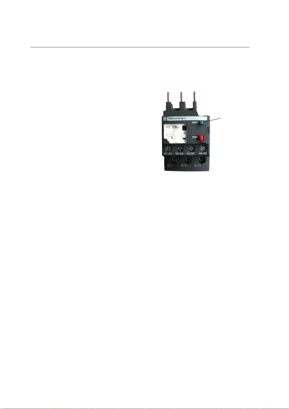
5. Reset Button
The reset protects the beater motor from an overload condition. If an overload
occurs, the reset mechanism will trip. The machine shuts down, it appears no power
supply.
Firstly find out the reason of protection,
solve problem.
Check the power supply, make sure
properly connected with power supply.
Lower viscosity setting in SET MENU item1.
Then press the reset button (blue color
button) in the thermal overload relay.
Figure 5-3.
WARNING:
Do not use metal objects to press the reset button. Failure to comply may result in
severe personal injury or death.
Press the WASH button and observe the machine's performance. If the beater motor
is turning properly, press the RESET button to cancel the cycle. Press other button to
resume normal operation. If the machine shuts down again, contact your authorized
service technician.
6. PRESSURE SWITCH
It protects the refrigeration system and causes the compressor to stop if the pressure
of the system exceeds the pressure switch setting value. This may occur especially
due to a lack of air circulation problems. The switch resets itself automatically.
WARNING:
If the compressor runs for an excessive time or stops and starts repeatedly, this
indicates insufficient condensation; check the causes and contact authorized service
technician.
Figure 5-3
Reset button

Page16
Section6 Operating Procedures
The machine has been selected to illustrate the pictured step-by-step operating
procedures. It has a 1.7liter capacity in freezing cylinder. The mix flows by gravity from
the hopper to the freezing cylinder through an air tube.
We begin our instructions at the point where we enter the store in the morning and find the
parts disassembled and laid out to air dry from the previous night’s cleaning.
These opening procedures will show you how to assemble these parts into the freezer with
fresh mix in preparation to serve your first portion.
Only there is raw material in the mix hopper can you run the machine “Cool”. You should
STOP the machine if there is no raw material in the hopper.
There are close relations between hardness setting up and environment temperature
producing the finished product actually.
Assembly
Note: When lubrication parts, use an approved food grade lubricant.
Step 1
Install the beater assembly.
Slide the beater o-ring into the flange on the
drive shaft of the beater assembly.
DO NOT LUBRICATE THE HEX END.
Insert the beater assembly through the rear shell bearing at the back of the freezing
cylinder and engage the hex end firmly into the female socket. When properly seated, the
beater will not protrude beyond the front of the freezing cylinder. Beater rotation must be
clockwise as viewed looking into the freezing cylinder.
Step 2
1. Assemble the freezer door. Place the large o-ring into the grooves on the back of the
freezer door and lubricate with lubricant.
2. Assemble the dispensing valve. Slide the O-rings and O-O ring into the grooves on
the draw valve and lubricate with lubricant.
3. Assemble the dispensing handle with dispensing handle retention. Insert the
dispensing handle through the slotted opening in the dispensing valve and align the
other end with the cross holes of the dispensing door.
Hint: The dispensing handle may be aligned with left or right cross hole. The
dispensing valve handle will be placed through the opposite cross hole of the
dispensing handle.
Insert the dispensing valve handle through the opposite cross hole and into the opening
of the dispensing handle.
Hint: The dispensing valve handle can be assembled at varied vertical positions.
Choose an angle which is comfortable for you. The dispensing valve must be raised
completely when the dispensing valve handle is down.

Page 17
Section6 Operating Procedures
4. Assemble three design caps to the bottom of the dispensing door spout.
.
Step 3
Install the freezer door. Insert the hand screws into the slots in the freezer door. With
both hands, hold the sides of the beater assembly. Finger-tighten the hand screws
equally drive shafts. Finger-tighten the hand screws equally to insure that the door is
snug. Don’t over-tighten.
ITEM
Part Number
QTY.
Description
1
225206007
1
Middle Dispensing Valve
2
225206004
2
Side Dispensing Valve
3
225206006
4
O-ring
4
225206002
1
O-O ring
5
225206005
1
Dispensing Handle Retention
6
225206001
1
Dispensing door
7
225206008
3
Dispensing Handle
8
225206009
2
Screw cap
9
225206003
3
Design Cap
10
225206031
2
Beat Pole
11
225020601
2
Seal of Dispensing Door
12
225206032
2
Bearing Front
3
4
1
2
5
6
7
8
9
1 0
1 1
1 2
Table of contents
Other Spaceman Ice Cream Maker manuals

Spaceman
Spaceman 6210-60Hz User manual

Spaceman
Spaceman 6228AH User manual

Spaceman
Spaceman SM-6228H User manual

Spaceman
Spaceman SM-6450 User manual

Spaceman
Spaceman 6220 Series User manual

Spaceman
Spaceman SM-6210 User manual

Spaceman
Spaceman 6210 User manual

Spaceman
Spaceman SM-6695H User manual

Spaceman
Spaceman Gravity Fed Machine User manual

Spaceman
Spaceman SM-6455H User manual


Popular Ice Cream Maker manuals by other brands


Domo
Domo DO2309I Instruction booklet

Proficook
Proficook PC-ICM 1091 N instruction manual

Silvercrest
Silvercrest SECM 12 B4 operating instructions

GBG
GBG Granismart Evolution operating instructions

Nissei
Nissei NA9420AEG Operator's manual

Brentwood
Brentwood Snow Cone Maker Operating and safety instructions