Spasciani BVF User manual
SPASCIANI SPA
Via Saronnino, 72
21040 ORIGGIO (VA), ITALY
Tel. +39 - 02-9695181 -Fax +39 - 02-96730843
info@spasciani.com - www.spasciani.com
AUTORESPIRATORI AD ARIA COMPRESSA
SELF-CONTAINED BREATHING APPARATUS
EQUIPO AUTÓNOMO DE AIRE COMPRIMIDO
RESPIRATEUR ISOLANT
BVF
IT Istruzioni per l’uso
ES Instrucciones de uso
EN Instructions for use
FR Mode d'emploi

Pag. 2 / 41
IT NOTA INFORMATIVA PER L’USO E LA MANUTENZIONE
AVVERTENZA
Solo l’osservanza di questo manuale di istruzioni garantisce un utilizzo sicuro dei dispositivi di protezione individuale
(DPI di III categoria, come definiti nel Regolamento (UE) 2016/425), descritti in questo manuale.
SPASCIANI S.p.A. non si assume alcuna responsabilità per danni che si verificassero in seguito a:
- inosservanza del presente manuale di istruzioni
- utilizzo del dispositivo per impieghi differenti da quelli descritti nel presente manuale
- riparazioni e sostituzioni di parti componenti eseguite da personale non autorizzato o con ricambi non originali.
Tutti i dati riportati nel presente manuale di istruzioni sono stati attentamente verificati. La SPASCIANI S.p.A. tuttavia
non si assume alcuna responsabilità per eventuali errori o errate interpretazioni del testo e si riserva il diritto di
modificare in tutto o in parte le caratteristiche tecniche dei propri prodotti senza obbligo di preavviso.
1. GENERALITA’
1.1. DESCRIZIONE GENERALE
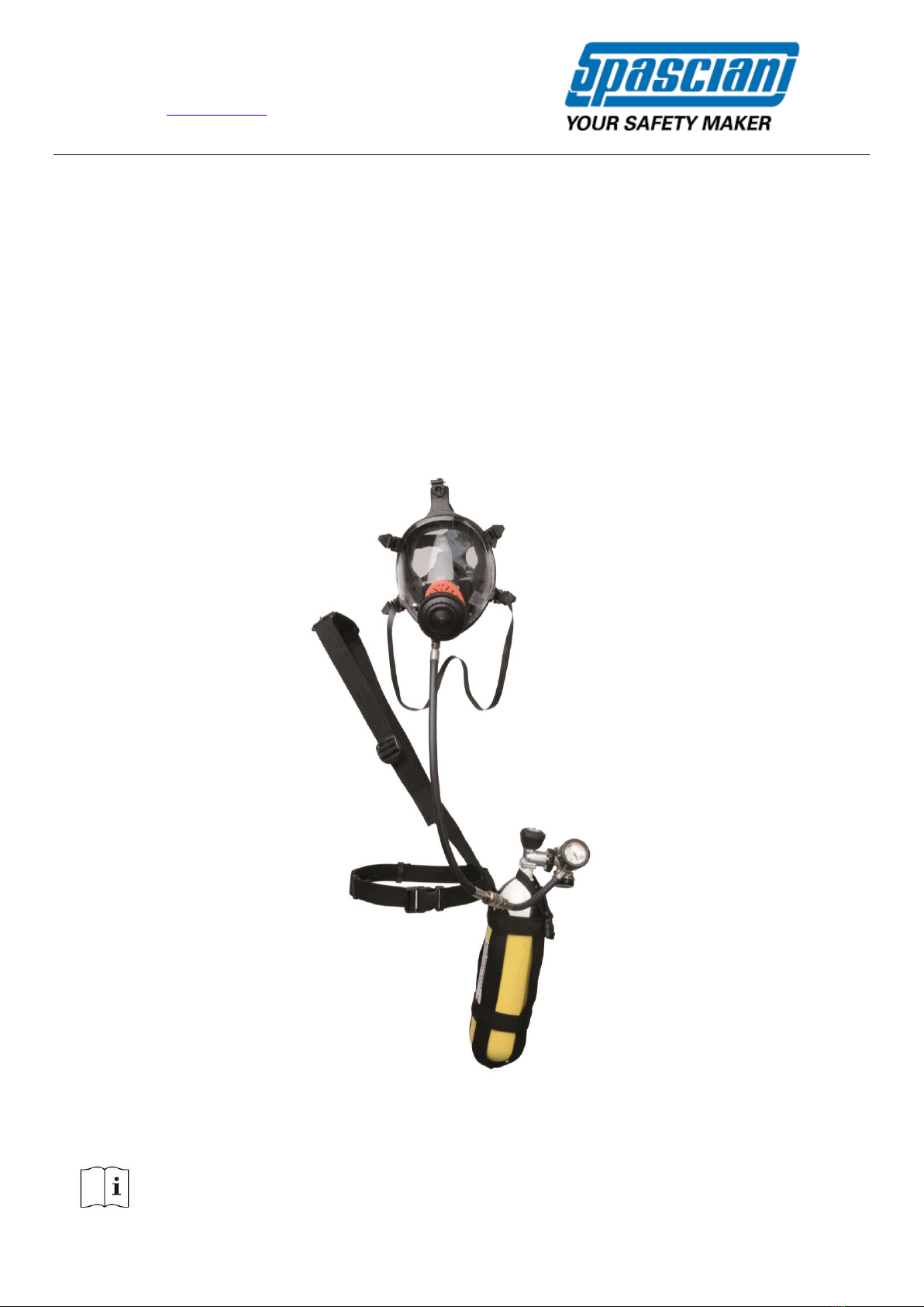
Gli autorespiratori SPASCIANI della serie BVF sono apparecchi ad aria compressa isolanti autonomi, a circuito aperto,
indipendenti dall’atmosfera ambiente. L’aria respirabile viene fornita all’utilizzatore da una bombola di aria compressa
per mezzo di un riduttore di pressione e un erogatore a domanda automatico collegato alla maschera intera; l’aria
espirata passa senza ricircolo dal facciale nell’atmosfera ambiente attraverso la valvola di espirazione.
Questa serie è compatibile con diversi tipi di bombole di aria compressa, maschere intere ed erogatori, nonché
accessori.
1.2. DESCRIZIONE MODELLI
Gli autorespiratori SPASCIANI serie BVF sono classificati come segue (in accordo alla norma EN 137:2006):
- tipo 1: apparecchio per uso industriale.
Ogni modello può essere configurato con i componenti (bombole, maschere, accessori) come riportato nel
Configuratore (vedi Tabella 3).
1.3. IMPIEGO PREVISTO, LIMITAZIONI
Gli autorespiratori BVF completi di bombola, maschera ed erogatore nelle combinazioni consentite descritte dal
configuratore, sono apparecchi di tipo 1, di costruzione leggera, adatti per brevi interventi di manutenzione in
stabilimenti chimici ed industriali o per la fuga da zone pericolose.
Le cinghie regolabili in lunghezza permettono di porre la bombola nella posizione più gradita sul fianco dell’operatore
o sul davanti permettendogli di muoversi anche in spazi ridotti.
È estremamente importante seguire le istruzioni per l’uso riportate in queste pagine, è vietato qualsiasi impiego
diverso da quello descritto nelle presenti istruzioni.
Gli apparecchi qui descritti NON SONO ADATTI ALL’USO SUBACQUEO anche se il loro funzionamento rimane inalterato
se immersi per un breve periodo in acqua.
La durata di impiego dipende dalla riserva d’aria a disposizione. Per maggiori dettagli riferirsi alla Tabella 1.
Utilizzare sempre aria respirabile secondo la norma EN 12021.
2. DESCRIZIONE DETTAGLIATA
Gli autorespiratori SPASCIANI della serie BVF sono costituiti da:
Sistema di supporto
Bombola d’aria compressa
Riduttore di pressione
Manometro di alta pressione
Erogatore automatico con segnalatore acustico
Maschera intera
e da eventuali
Accessori
Figure di riferimento:
Fig.1 per BVF
Fig.2 per il riduttore
Pag. 3 / 41
Fig.3 per l’erogatore
Fig.4 per la maschera
2.1. SISTEMA DI SUPPORTO (pos. A nella fig. 1)
Il sistema di supporto consiste in una bardatura formata da cinghie a tracolla (a1) e cintura in vita (a2), entrambe
regolabili in lunghezza, che permettono di indossare l’autorespiratore a tracolla e trattenere la bombola aderente al
corpo.
2.2. BOMBOLA CON VALVOLA (pos. B nella fig. 1)
Gli autorespiratori sono dotati di una bombola in acciaio o in composito, avente le caratteristiche tecniche
schematizzate nella seguente tabella:
Tab.1 –Caratteristiche tecniche bombole
Capacità
(l)
Pressione
(bar)
Diametro (mm)
Lunghezza
(mm)
Peso vuota
(kg)
Riserva*
(l)
Autonomia**
(min)
3 (acciaio)
300
115
420
5
830
27
3 (composito)
300
115
440
1.9
830
27
* Il contenuto di aria della bombola è dato dalla formula PxV, alla pressione di 200 bar; alla pressione di 300 bar non vale più la
formula PxV per calcolare il volume di aria disponibile ma bisogna considerare il fattore di compressibilità che porta ad una
riduzione di circa 8%.
**autonomia ottenuta considerando un consumo medio di circa 30 l/min per un operatore.
Le bombole sono dotate di valvole a volantino (b1) con filettatura conforme alla norma EN 144-1 per quanto concerne
il raccordo tra la valvola e la bombola (colletto con filettatura cilindrica M18x1.5) ed EN 144-2 per pressioni nominali
di lavoro di 300 bar, per quanto concerne il raccordo tra la valvola e il riduttore di pressione.
Le bombole e le valvole sono conformi alla direttiva PED 2014/68/UE e/o TPED 2010/35/EU ed alle regolamentazioni
nazionali del paese in cui vengono commercializzate e sono accompagnate dai relativi documenti (dichiarazioni di
conformità, certificati di collaudo, istruzioni per l’uso).
I dati identificativi sono stampigliati sulle bombole e sulle valvole come previsto dalle vigenti leggi o su una apposita
etichetta permanentemente attaccata alla bombola (bombole in composito). Le bombole sono verniciate secondo la
norma EN 1089-3.
L’aria per la respirazione fornita dalle bombole deve sempre essere conforme alla EN 12021.
Le valvole delle bombole possono essere fornite, a richiesta, con l’accessorio Excess Flow Valve (vedi accessori).
2.3. RIDUTTORE DI PRESSIONE (pos. C nella fig. 1 e fig. 2)
Il riduttore di pressione è costituito da un corpo in ottone e contiene i dispositivi cheriducono e mantengono la pressione
a 5,5 bar al variare di quella all’interno della bombola. In corrispondenza del valore di pressione della bombola di (705)
bar uno speciale dispositivo innalza la pressione di uscita a 8 bar causando l’inserimento del segnale di allarme alla
maschera.
Sul riduttore sono presenti:
- Raccordo EN 144-2 per la bombola (pos. 1 in fig. 2); il girello è rivestito in gomma
- Raccordo alta pressione (pos. 2 in fig. 2). Al raccordo di alta pressione è collegato il manometro (pos.3 in fig.2)
- Tubo a media pressione (pos. 4 in fig. 2) con raccordo rapido di sicurezza per l’alimentazione dell’erogatore. Il tubo a
media pressione è collegato al riduttore tramite un raccordo girevole (pos. 5 in fig. 2)
- Attacco ausiliario con tappo (pos. 6 in fig. 2). Sull’attacco ausiliario è possibile montare, rimuovendo il tappo,
l’accessorio “allarme supplementare” (vedi par. 2.7.2)
- Valvola di sicurezza (pos. 7 in fig. 2).
2.4. MANOMETRO (pos. D nella fig. 1 e pos. 3 nella fig. 2)
Il manometro è di tipo a molla con fermo di zero e rientra nei limiti di precisione della classe 1.6. È dotato di una cassa
in ottone nichelato ed è ricoperto con un guscio copri-manometro che lo protegge da urti. Il quadrante è luminescente,
con fondo scala di 360 bar, risoluzione di 5 bar e indicatore di riserva sotto i 50 bar. È presente una seconda scala in
PSI.
2.5. EROGATORE AUTOMATICO CON SEGNALATORE ACUSTICO (pos. E in Fig. 1 and Fig. 3)
L’erogatore è costituito da un involucro in materiale plastico rinforzato e contiene sia il dispositivo di dosaggio dell’aria
che quello di allarme acustico di esaurimento. È collegato al riduttore tramite un tubo di media pressione con raccordo
Pag. 4 / 41
snodato. Il pulsante (pos. 1 fig. 3) permette il bloccaggio del dispositivo di erogazione che viene attivato alla prima
inspirazione. L’erogatore può essere di tipo A o BN a seconda della versione delle maschere (vedi par. 2.6).
2.6. MASCHERA INTERA (Fig. 4)
Si riporta di seguito una descrizione delle maschere intere che possono essere impiegate con gli autorespiratori serie
BVF. Per i dettagli delle maschere che possono essere impiegate in ogni modello, vedere il configuratore.
•Tipo “A” a pressione positiva e con raccordo filettato EN 148-3 (M45x3), da utilizzare con erogatore di tipo A.
Modelli disponibili:
-TR 82 A (Cod. 112300000) certificata EN 136:98 in classe 3
-TR 2002 A CL3 (cod. 113000000), TR 2002 S A CL3 (cod. 113060000) certificate EN 136:98 in classe 3
Nota: Il funzionamento dell’autorespiratore, se dotato di raccordo EN 148-3, è comunque possibile con altre maschere
conformi alla stessa norma solo ed esclusivamente in casi di emergenza e nel caso in cui non sia disponibile (per cause
accidentali) la maschera corretta.
•Tipo “BN” a pressione positiva e con raccordo a baionetta DIN 58600, da utilizzare con erogatore di tipo BN. Le
maschere “BN” sono dotate anche di un raccordo aggiuntivo EN 148-1 (Rd 40x1/7”) che permetto l’uso con
dispositivi a pressione negativa (autorespiratori a pressione negativa o filtri).
Modelli disponibili:
-TR 2002 BN CL3 (cod. 113010000), TR 2002 S BN CL3 (cod. 113070000) certificate EN 136:98 in classe 3
•Tipo “B” a pressione positiva e con raccordo a baionetta DIN 58600, da utilizzare con erogatore di tipo BN.
Modelli disponibili:
-TR 82 B (Cod. 112310000) certificata EN 136:98 in classe 3.
Per maggiori dettagli sulle caratteristiche delle maschere e sul loro corretto impiego, vedere le istruzioni allegate ad
ogni maschera.
2.7. ACCESSORI
2.7.1. Valvola a 4 vie
Il raccordo automatico a 4 vie o valvola a 4 vie, accessorio fornibile a richiesta, permette:
-di alimentare un secondo operatore, che sarà dotato di segnale di allarme individuale in maschera;
-di collegare l’autorespiratore ad una fonte alternativa di aria per prolungare l’autonomia e/o permettere una fuga
sicura nel caso di interruzione accidentale della fonte di alimentazione principale. Durante l’alimentazione dalla fonte
alternativa (a 5.5 bar) la bombola è automaticamente esclusa.
Le istruzioni dettagliate per l’utilizzo della valvola a 4 vie sono allegate all’accessorio stesso.
2.7.2. Allarme supplementare
L’allarme supplementare è un accessorio montabile a richiesta su tutti gli autorespiratori serie BVF e permette di avere
un segnale di allarme in continuo, in aggiunta al segnale di allarme intermittente già previsto nell’erogatore.
Viene montato sul riduttore e si attiva contemporaneamente all’allarme principale.
2.7.3. Valvola di sovra flusso (Excess flow valve)
La valvola della bombola può essere dotata, a richiesta, di una valvola di sovra flusso.
2.7.4. Raccordi media pressione
Il tubo di media pressione, che collega il riduttore all’erogatore, può essere dotato di raccordi rapidi di tipo
Eurocouplings (di serie) in alternativa ai raccordi di tipo Spasciani (a richiesta).
2.7.5. Autorespiratori ATEX
A richiesta, gli autorespiratori possono essere forniti nella versione “Atex”. Vedi par.8 per i dettagli di questa linea di
apparecchi.
3. USO
Avvertenze
Tutte le operazioni di predisposizione e utilizzo dell’autorespiratore devono essere eseguite solamente da personale
competente e addestrato. Accertarsi che qualsiasi accessorio o dispositivo ausiliario o qualsiasi altro tipo di indumento
protettivo utilizzato in aggiunta non sia di intralcio e non comprometta la sicurezza e la tenuta.
L’autonomia dell’autorespiratore dipende dalla quantità di aria iniziale disponibile e dalla frequenza respiratoria
dell’operatore, nonché della presenza di accessori che potrebbero consumare aria (es. allarme supplementare).
Pag. 5 / 41
Devono essere utilizzati apparecchi sempre preventivamente controllati. Prima dell'uso è obbligatorio eseguire le
operazioni di seguito descritte.
3.1. PRIMA DELL’USO
3.1.1. Montaggio delle bombole
Porre la bombola nell’alloggiamento della cinghiatura ed assicurarla con l’apposita fibbia (pos. a3 fig.1). Collegare la
bombola al riduttore.
3.1.2. Allacciamento dell’erogatore
Innestare i raccordi rapidi maschio e femmina del tubo di media pressione. Con una lieve pressione si ottiene
l’allacciamento.
N.B.: Lo scollegamento si ottiene esercitando una lieve pressione assiale sul raccordo ed arretrando
contemporaneamente la ghiera del raccordo femmina. Non disconnettere se la tubazione è sotto pressione!
Premere il pulsante di bloccaggio dell’erogatore (pos. 1 fig. 3) per evitare perdite d’aria mentre si indossa
l’apparecchio.
3.1.3. Controllo carica bombola
Inserire il dispositivo di bloccaggio (pos. 1 fig. 3). Aprire la valvola della bombola: la pressione non dovrà essere
inferiore a 280 bar per bombole da 300 bar di esercizio.
3.1.4. Controllo tenuta pneumatica della sezione alta pressione
Chiudere la valvola della bombola. La pressione non deve scendere più di 20 bar in un minuto.
3.1.5. Controllo del segnale di allarme
• Aprire la valvola della bombola e mettere l’apparecchio sotto pressione
• Chiudere la valvola della bombola
• Sganciare il dispositivo di bloccaggio (pos. 1 fig. 3) agendo sul pulsante in gomma al centro del coperchio
dell’erogatore
• Chiudere con il palmo della mano l’uscita dell’aria dall’erogatore, quindi lasciar sfuggire l’aria lentamente. Osservare
il manometro e al raggiungimento della pressione di (70±5) bar si dovrà sentire, scaricando fortemente, una forte
vibrazione sonora che cesserà al terminare dell’aria disponibile nella tubazione. N.B.: si raccomanda di scaricare l’aria
molto lentamente e di attendere qualche secondo in corrispondenza delle pressioni di taratura dell’allarme.
• Reinserire il dispositivo di bloccaggio (pos. 1 fig. 3).
3.2. INDOSSARE L’APPARECCHIO
Far passare la cinghia a bandoliera sopra la testa e posarla sulla spalla destra. Allacciare la cinghia in vita. Entrambe le
cinghie sono regolabili in lunghezza. La bombola può essere portata a piacere sul davanti o sul lato.
Una volta indossato l’apparecchio:
• Indossare la maschera e controllare la tenuta sul viso (vedi istruzioni specifiche delle maschere)
• Aprire la valvola della bombola di almeno due giri
• Collegare l’erogatore al raccordo della maschera: alla prima inspirazione il dispositivo di bloccaggio (pos. 1 fig. 3) si
sblocca e mantiene la pressione positiva nel facciale.
Per collegare l’erogatore alla maschera agire nel seguente modo:
- Erogatore e maschera tipo A, raccordo a vite normalizzato EN 148-3 (M45x3): avvitare il girello maschio dell’erogatore
nel raccordo femmina della maschera fino a battuta.
- Erogatore e maschera tipo B e BN con raccordo a baionetta: inserire il raccordo maschio dell’erogatore nel bocchettone
della maschera e spingere fino a quando i dentini dell’erogatore non si agganciano nell’apposito bordo di tenuta sulla
maschera.
N.B.: Il collegamento al facciale dell’erogatore deve essere effettuato e controllato da una seconda persona.
L’autorespiratore è ora pronto per l’uso.
3.3. DURANTE L'USO
Controllare di tanto in tanto con il manometro la pressione residua della riserva d’aria. Quando la pressione scende
sotto i (70±5) bar il segnalatore di allarme viene attivato. Ad ogni inspirazione corrisponderà allora un forte segnale
sonoro. Il segnale dura fino al completo esaurimento della riserva d’aria.
N.B.: Allontanarsi dal luogo a rischio quando si sente il segnale di esaurimento.
In caso di emergenza (maggior sforzo fisico o resistenza respiratoria accresciuta) è possibile agire brevemente e
ripetutamente sul bottone in gomma dell’erogatore per immettere direttamente aria in maschera.
Pag. 6 / 41
3.4. DOPO L'USO
• Chiudere la valvola della bombola
• Scollegare l’erogatore dalla maschera, lasciando scaricare l’aria contenuta e poi premere il pulsante (pos. 1 fig. 3):
- Maschera ed erogatore e tipo A: svitare il girello dell’erogatore
- Maschera ed erogatore e tipo B e BN: premere contemporaneamente i pulsanti di blocco e scollegare l’erogatore dalla
maschera
• Slacciare la cintura in vita
• Levare la maschera
• Deporre l’apparecchio a terra senza farlo cadere.
4. MANUTENZIONE
La SPASCIANI S.p.A. non si assume alcuna responsabilità per i danni che si verificassero in seguito ad operazioni di
manutenzione o riparazione non eseguite negli stabilimenti della stessa società o di altri da essa espressamente
autorizzati.
4.1. PULIZIA E DISINFEZIONE
Dopo ogni uso è necessario provvedere alla pulizia delle parti sporche. Ciò deve essere fatto con acqua saponata
tiepida. Il risciacquo deve essere eseguito con acqua corrente. Per rimuovere gli accumuli di polvere pulire con panno
umido o con prodotti antistatici.
N.B.: Nell’uso dei prodotti chimici per la disinfezione seguire le indicazioni di concentrazione. Evitare l’uso di solventi
organici che possono danneggiare le parti in gomma e plastica.
4.2. BOMBOLE
Per la ricarica e il ricollaudo delle bombole seguire le leggi e i regolamenti in vigore nel paese di utilizzazione e relativi
alla tipologia di bombole impiegate.
Nella ricarica è ammesso superare la pressione massima di esercizio di circa il 10%, in quanto quando la temperatura
ritorna a quella ambiente la pressione ridiscende al valore nominale.
Per la ricarica assicurarsi che:
• L’aria corrisponda a EN 12021
• La bombola sia stata verificata nei limiti temporali previsti, verificando la stampigliatura dell’ultimo ricollaudo.
La valvola della bombola deve essere mantenuta chiusa durante il trasporto ad evitare che l’umidità atmosferica possa
penetrare e lì condensare.
Le bombole durante il trasporto e il magazzinaggio devono essere protette dagli urti.
Non trasportare le bombole afferrandole per la valvola.
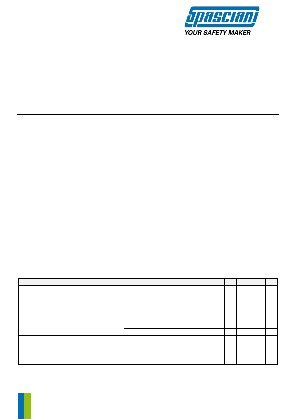
4.3. MANUTENZIONE PROGRAMMATA
La seguente tabella indica gli interventi di manutenzione previsti:
Tabella 2 –Manutenzione programmata
Parte
Attività
1
2
3
4
5
6
7
Autorespiratore completo
Pulizia
X
Funzionamento, tenuta
X
X
Controllo bardatura
X
Erogatore
Pulizia
X
Disinfezione
X
Prova Membrana
Xa
X
Sostituzione Membrana
X
Raccordo Apparecchio
Prova filetto (calibro)
X
Guarnizione raccordo alta pressione
Sostituzione
X
Riduttore
Revisione
X
Bombola
Ricollaudoc
Xb
1: Prima di ammetterlo all'uso - 2: Prima dell’uso - 3: Dopo l'uso - 4: Ogni sei mesi - 5: Annualmente - 6: Ogni tre anni - 7: Ogni sei
anni.
a) Dopo l'uso in ambienti corrosivi o in condizioni ambientali estreme

Pag. 7 / 41
b) In base alle leggi nazionali
c) ATTENZIONE: Ad ogni smontaggio della valvola dalla bombola, è necessario sostituire la valvola con una nuova. Per le corrette
coppie di serraggio fare riferimento alle istruzioni per l’uso specifiche della bombola e della valvola. Dopo la sostituzione di una
qualsiasi parte è necessario eseguire tutti i controlli di funzionamento e tenuta pneumatica.
4.4. CONTROLLI
Avvertenza: i seguenti controlli devono essere assolutamente eseguiti dopo la pulizia o la sostituzione di parti
componenti.
La membrana dell’erogatore come pure tutte le parti in gomma devono essere sostituite se mostrano segni di
alterazione od invecchiamento quali screpolature, parti appiccicose, deformazioni, ecc. Tutti i raccordi devono
presentarsi scorrevoli senza impedimenti e non mostrare danneggiamenti.
Alcune delle prove seguenti possono essere eseguite mediante l’uso di apposite attrezzature che SPASCIANI fornisce
a richiesta.
4.4.1. Prova di tenuta dell'erogatore alla pressione di 7 mbar
• Collegare la bombola al riduttore; la bombola va lasciata chiusa
• Collegare l’erogatore alla cannula di media pressione
• Rilasciare il pulsante di bloccaggio (pos. 1 dis. 3) agendo sul bottone al centro del coperchio
• Collegare l’erogatore all’apparecchiatura di prova
• Creare una pressione di circa 7 mbar nell’erogatore.
La caduta di pressione non deve essere superiore a 1 mbar in un minuto.
4.4.2. Sovrappressione statica dell'erogatore
• Aprire la valvola della bombola
• Collegare l’erogatore all’apparecchiatura di prova
• Sbloccare il pulsante (pos. 1 dis. 3) agendo sul bottone in gomma al centro del coperchio.
La pressione deve essere compresa tra 3,2 e 3,9 mbar.
4.4.3. Prova della pressione di carica della bombola
Vedi par. 3.1.3
4.4.4. Prova della tenuta pneumatica della sezione alta pressione
Vedi par. 3.1.4
4.4.5. Prova del segnale di allarme
Vedi par. 3.1.5.
5. IMMAGAZZINAGGIO E TRASPORTO
Gli apparecchi devono essere conservati in locali freschi e ventilati, lontani da gas o agenti corrosivi e dall’azione diretta
dei raggi solari o di fonti di calore. Gli autorespiratori puliti ed asciutti possono essere conservati in armadi o valigie a
tenuta di polvere. Bisogna a questo scopo accertarsi che gli apparecchi poggino sugli schienali e che le cinghie non
siano mantenute piegate.
I dispositivi, conservati nel loro imballaggio originale o nell’apposita valigia, non richiedono cure particolari per il
trasporto. È tuttavia consigliato osservare le indicazioni di massima già evidenziate per il magazzinaggio.
6. CERTIFICAZIONE
Gli autorespiratori BVF SPASCIANI sono conformi alla norma EN 137:2006 e soddisfano i requisiti del Regolamento DPI
(2016/425/UE) e delle Direttive PED (2014/68/UE) e ATEX (2014/34/UE).
DPI –Organismo notificato che ha eseguito le prove di tipo per la certificazione CE ed effettua il controllo di produzione
secondo il Modulo D del Regolamento (UE) 2016/425: Italcert S.r.l., Viale Sarca 336, 20126 Milano –Italia, O.N. n°
0426.
PED –I dispositivi sono realizzati in conformità ai requisiti dei Moduli di valutazione della Conformità B+D secondo la
direttiva 2014/68/UE sui Dispositivi a pressione. Organismo di verifica dei moduli B+D: Italcert Srl, Viale Sarca 336,
20126 Milano –Italia, O.N. n° 0426.
ATEX –I dispositivi sono approvati con un Certificato volontario di esame del Tipo (All.3 della Dir. 2014/34/UE) emesso
da: CEC S.c.a.r.l, Via Pisacane 46, 20005 Legnano (Mi) –Italia, O.N. n°1131.
Tutti gli autorespiratori SPASCIANI soddisfano i requisiti del Regolamento DPI (2016/425/UE) e della Direttiva PED
(2014/68/UE).

Pag. 8 / 41
Tutti gli autorespiratori BVF possono essere forniti nella versione ATEX.
7. MARCATURE
Tutte le parti importanti per la sicurezza dell’apparecchio sono marcate con il numero di serie e con la data di
produzione.
1. Sul riduttore è presente un’etichetta adesiva recante il codice a barre (13 cifre) ed è anche stampigliata in maniera
indelebile una matricola di 9 cifre dove le ultime sette cifre corrispondono a parte del codice a barre presente
sull’etichetta. Il riduttore è sigillato in fabbrica ed il sigillo porta la data dell’ultimo controllo. Questo numero
univoco per ogni autorespiratore è il numero di serie dell’apparecchio.
2. Sull’erogatore è presente un’etichetta adesiva recante il codice a barre (13 cifre). In aggiunta all’etichetta con il
codice a barre, sull’erogatore è stampigliata una matricola di 9 cifre, dove le ultime sette cifre corrispondono a
parte del codice a barre assegnato.
3. I tubi sono marcati con la data di fabbricazione.
4. La membrana dell’erogatore ed altre parti in gomma riportano un “orologio” datario indicante anno e mese di
fabbricazione.
5. L’apparecchio completo ha una etichetta posta su una placchetta metallica fissata alla cinghia della bardatura
(vedi esempio A - etichetta) che riporta tutte le marcature richieste da Direttive e Norme tecniche di riferimento:
- Nome e indirizzo del fabbricante (A)
- Nome del modello (B)
- Marcatura (C) che indica la rispondenza ai requisiti essenziali stabiliti rispettivamente dal Regolamento
2016/425/UE e dalla Direttiva 2014/68/UE, seguita dal numero dell'Organismo Notificato che effettua il controllo
di produzione (N° 0426 Italcert S.r.l., V.le Sarca, 336, 20126 Milano - Italia)
- Norma di riferimento per il Regolamento (UE) 2016/425: EN 137:2006 e classificazione dell’apparecchio (Tipo 1) (D)
- Pressione massima di esercizio (PS) e Temperature minima e massima di esercizio (TS) (E)
- Data (aaaa) di produzione (F)
Esempio A - Etichetta
8. Linea AUTORESPIRATORI ATEX
UTILIZZO IN ATMOSFERE POTENZIALMENTE ESPLOSIVE
Gli autorespiratori BVF che recano in aggiunta la marcatura sono disponibili nella versione ATEX per l’uso in
atmosfere potenzialmente esplosive e sono certificati anche secondo la Direttiva 2014/34/UE.
I gruppi per i quali sono stati certificati gli apparecchi sono sia I che II e pertanto sono utilizzabili sia in superficie che
in miniere. Sono apparecchi di categoria 1 e M1 e idonei per l’impiego nelle zone 0 (zona con rischio di esplosione
continuativo o molto frequente per la presenza di sostanze esplosive gassose G) e zona 20 (zona con rischio di
esplosione continuativo o comunque molto frequente per la presenza di polveri esplosive D) sia in superficie che in

Pag. 9 / 41
miniere. Gli autorespiratori ATEX riportano sul telaio un’etichetta sul telaio (vedi esempio B – etichetta Atex) che
riporta tutte le marcature richieste dalla Direttiva 2014/34/UE e dalle norme tecniche di riferimento
Esempio Etichetta Atex
Dove:
Simbolo CE indicante la conformità alla Direttiva 2014/34/UE
1131 Numero di identificazione organismo notificato coinvolto nella sorveglianza della produzione
marcatura specifica della protezione contro l’esplosione
I, II Gruppo apparecchi: I→ miniere II → superficie
1, M1 Categoria apparecchi: 1→ Livello molto alto (superficie) M1 → Livello molto alto (miniere)
GD Categoria apparecchi G → Gas, vapori D → Polveri
c Tipo di protezione usato c→ sicurezza costruttiva
IIC Gruppo del gas IIC → Idrogeno, Acetilene, ...
T4 Temperatura superficiale delle apparecchiature
CEC Ente notificato che ha emesso il certificato di esame CE del Tipo
13 Anno di prima emissione del certificato di esame CE del Tipo
ATEX 078 rev.2 Numero del certificato di esame CE del Tipo
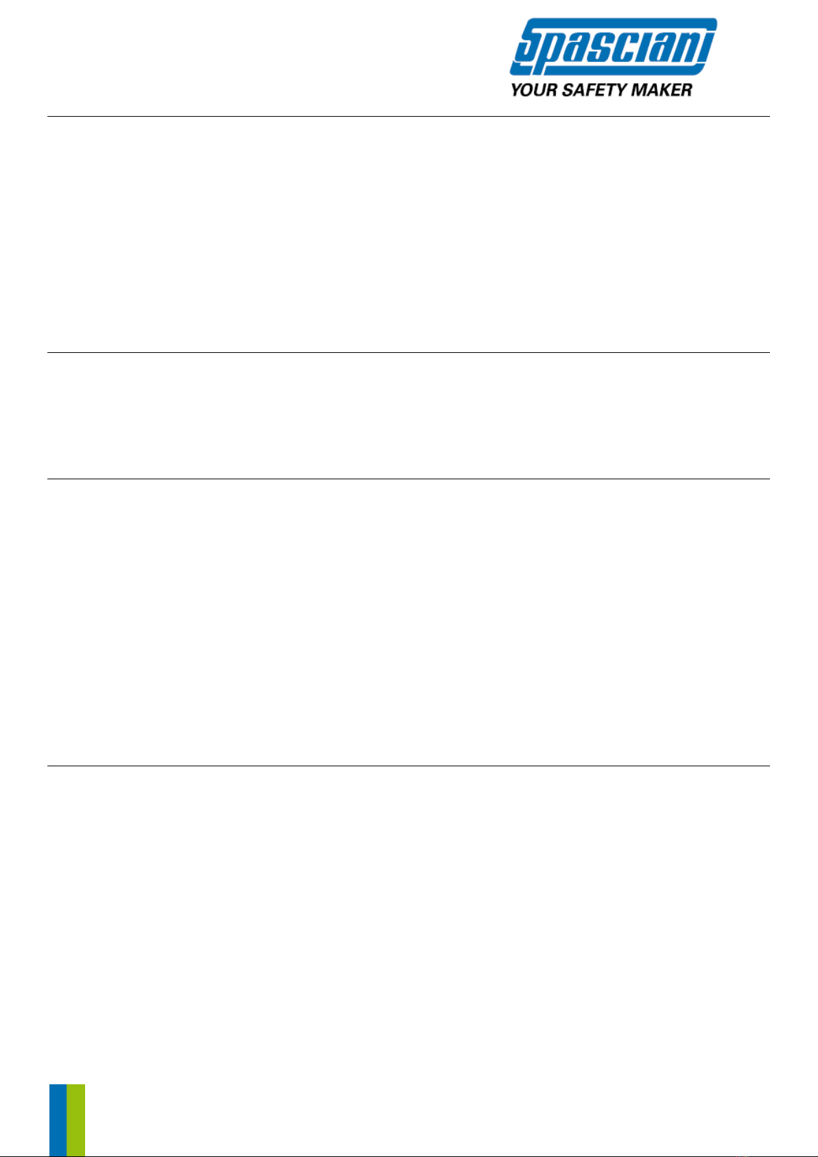
9. DATI TECNICI
Pressione esercizio max
300 bar
Pressione attivazione allarme
70 ± 5 bar
Media pressione
5.5 bar
Temperatura di funzionamento
-30°C / +60°C
9.1. Pesi / Dimensioni
Descrizione
DimensioniHxLxP
(mm)
Peso circa
(Kg)
BVF con maschera e bombola 3 l 300 bar acciaio carica
165x550x110
9.5
BVF con maschera e bombola 3 l 300 bar composito carica
165x550x110
6
9.2. Materiali
Cinghie
Nastro in fibre autoestinguenti
Riduttore
Ottone cromato
Erogatore
Involucro in nylon rinforzato con fibre di vetro
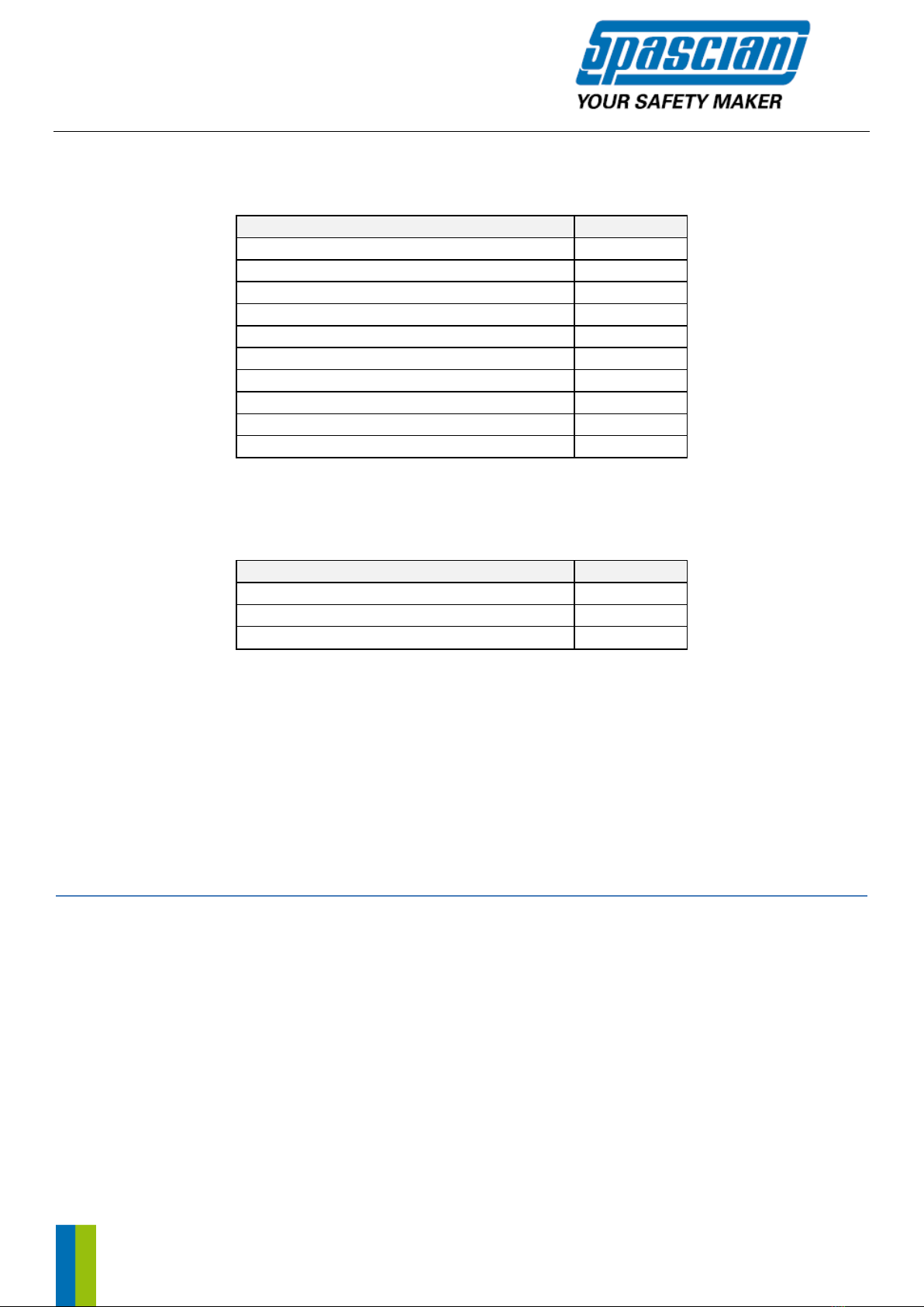
10. CODICI PER ORDINE, PARTI DI RICAMBIO E ACCESSORI
Codici modelli
I codici qui riportati si riferiscono al modello base costituito dalla bardatura e dal riduttore dotato di tubo media
pressione e di manometro; il modello base prevede raccordi rapidi riduttore-erogatore di tipo Eurocouplings e nessun
accessorio (es. allarme supplementare). Per ordinare autorespiratori con gli altri raccordi disponibili (di tipo Spasciani)
e con eventuali accessori contattare l’ufficio commerciale.
Descrizione
Codice
BVF bardatura + riduttore con manometro e tubo M.P.
158250000
Pag. 10 / 41
Componenti
Per completare l’autorespiratore, devono essere abbinati i componenti come da configuratore. Di seguito i codici dei
componenti che sono anche forniti come ricambi.
Descrizione
Codice
Maschera TR 2002 A CL3
113000000
Maschera TR 2002 S A CL3
113060000
Maschera TR 2002 BN CL3
113010000
Maschera TR 2002 S BN CL3
113070000
Maschera TR 82 A
112300000
Maschera TR 82 B
112310000
Erogatore BN EC
1579100CJ
Erogatore A EC
1588500CJ
Bombola 3 l 300 bar *
923030000
Bombola 3 l 300 bar in composito *
92303000C
* Gli apparecchi sono certificati per l’uso con bombole in acciaio prodotte da Worthington, ECS e ISER e con bombole in materiale
composito prodotte da Luxfer e CTS. Le bombole sono dotate di valvole prodotte da SAN-O-SUB.
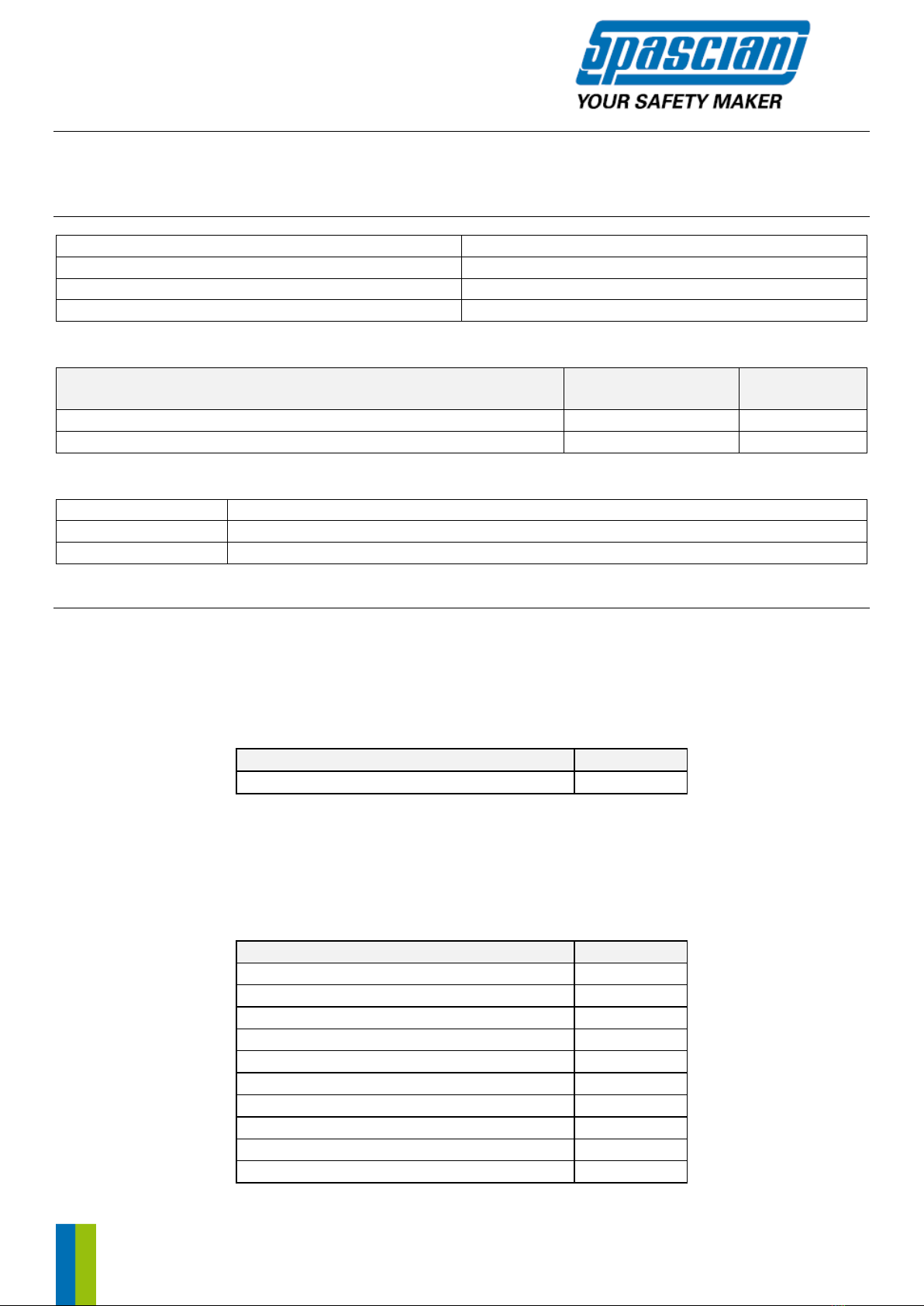
Accessori
Descrizione
Codice
Valvola 4 vie
932440000
Allarme supplementare
152530000
Excess Flow valve
936010000
Per parti di ricambio ed accessori non presenti in questo elenco, contattare il servizio clienti di SPASCIANI.
ATTENZIONE: in virtù dei raccordi standard conformi alle norme EN 144 si possono impiegare altre bombole, oltre a
quelle qui previste e descritte, in via del tutto eccezionale ed esclusivamente in situazioni di emergenza (qualora le
bombole in dotazione non fossero disponibili).
L’utilizzatore dovrà verificare la rispondenza delle attrezzature in pressione ai requisiti imposti dalle legislazioni vigenti
in campo di recipienti ad alta pressione e relativi accessori e la compatibilità, anche costruttiva (per esempio raccordi
e ingombri massimi), delle bombole con gli apparecchi stessi.
SPASCIANI S.p.A. non si assume alcuna responsabilità per l’eventuale assemblaggio non autorizzato di bombole non
fornite dalla stessa e non richiamate nel presente manuale, o comunque per ogni eventuale assemblaggio effettuato
in maniera difforme da quanto specificatamente riportato nel seguente manuale.
EN INFORMATION NOTICE FOR USE AND MAINTENANCE
WARNING
Strictly follow the instructions contained in this manual to make sure the personal protective equipment (3rd category
PPE as defined in Regulation (EU) 2016/425) described herein is used appropriately.
SPASCIANI S.p.A. will not be liable for damage caused because of:
-failure to comply with this manual
-failure to use the device as intended, i.e. for uses other than the ones described in this manual
-failure to use authorized personnel to carry out the repair and replacement operations or failure to use non-original
spare parts.
All the information reported in this instructions manual was carefully reviewed. SPASCIANI S.p.A. will nonetheless not
be liable for any errors or misinterpretations and thus reserves the right to modify all or part of the technical features
of its products without prior notice.

Pag. 11 / 41
1. GENERAL
1.1. PRODUCT OVERVIEW
The SPASCIANI BVF series device is a self-contained breathing apparatus (SCBA) that uses an open-circuit breathing
system, not depending from the environment.
The breathable air is supplied to the user from a cylinder of compressed air by means of a pressure reducer and an
automatic demand valve connected to the mask; exhaled air flows to the ambient atmosphere through the exhalation
valve without recirculation inside the mask.
The series in compatible with a wide range of compressed air cylinders, full face masks and demand valves, as well as
with various accessories.
1.2. FEATURE DESCRIPTION
SPASCIANI BVF self-contained breathing apparatuses are classified, in accordance with the EN 137:2006 standard, as
follows:
-Type 1: device for industrial use.
Each apparatus shall be assembled in different approved configuration (e.g. steel or composite cylinder, full face
masks, accessories) as described in the Configurator (See table 3).
1.3. INTENDED USE, LIMITATIONS
The BVF breathing apparatus, complete with cylinder, mask and demand valve in the combinations described by the
Configurator, are light duty Type 1 SCBA designed for short inspection and maintenance interventions in chemical
plants or for escape.
The adjustable straps allow to put the cylinder in the most pleasing position on the side of the operator or on the front
allowing him to move even in small spaces.
It is extremely important to follow the instructions for use reported on this booklet and it is strictly forbidden to use
the device for purposes other than the ones described in these instructions.
The devices described herein ARE NOT SUITABLE FOR UNDERWATER USE even if their functions remain unaffected
when submerged in water for a short period of time.
Their autonomy depends on the air reserve available. Refer to Table 1 for more information.
Always use breathable air according to the EN 12021 standard.
2. DETAILED DESCRIPTION
The breathing apparatus BVF consists of the following elements:
Carrying system
Air pressure cylinder
Pressure reducer
High pressure gauge with connection hose
Demand valve with audible warning device
Full face mask
and any
Accessories
Reference figures:
Fig. 1 for BVF
Fig. 2 for the pressure reducer
Fig. 3 for the demand valve
Fig. 4 for the full-face mask
2.1.CARRYING SYSTEM (pos. A in Fig. 1)
The carrying system consists of a harness formed by shoulder straps (a1) and waist belt (a2), both adjustable in length,
that allow to carry on the shoulder the device and hold the cylinder close to the body.
2.2.CYLINDER WITH VALVE (pos. B in Fig. 1)
The BVF are equipped with a steel or composite cylinder whose technical features are summarized in the following
table:

Pag. 12 / 41
Tab.1 –Technical features of the cylinders
Capacity
(l)
Pressure
(bar)
Diameter
(mm)
Length
(mm)
Weight
empty (kg)
Reserve*
(l)
Autonomy**
(min.)
3 (steel)
300
115
420
5
830
27
3 (composite)
300
115
440
1.9
830
27
*at a pressure of 300 bars, the PxV formula is no longer used to calculate the volume of air available, you must consider the
compressibility factor, which leads to a reduction of about 8%.
**autonomy achieved for an average consumption of about 30 l/min. per operator.
The cylinders are equipped with hand wheel valves (b1) with threads connection according to the EN 144-1 standard
as far as the connection between the valve and cylinder is concerned (cylinder neck thread M18x1.5) and to the EN
144-2 for nominal operating pressures of 300 bar as far as the connection between the valve and pressure reducer is
concerned.
The cylinders and valves are in accordance with the PED 2014/68/UE and/or TPED 2010/35 EU Directives and with the
national regulations of the countries in which they are marketed. They are also provided with all the relevant
documents (declarations of conformity, test certificates, instructions for use).
The identification data is printed on the cylinders and valves as required by the applicable laws or on a special permanent
label applied to the cylinder (composite cylinders). The cylinders are painted according to the EN 1089-3 standard.
Breathable air is provided by the cylinders and must always be in accordance with the EN 12021 standard.
The valves of the cylinders can be provided with the Excess Flow Valve accessory upon request (see accessories).
2.3. PRESSURE REDUCER (pos. C in Fig. 1 and Fig. 2)
The pressure reducer has a brass body and contains the devices which reduce and maintain the pressure at 5.5 bar
depending on the pressure inside the cylinder. When the cylinder pressure reaches (705) bar, a special device increases
the output pressure to 8 bar, thus turning the alarm signal of the mask on.
The reducer consists of the following elements:
- EN 144-2 connection for the cylinder (pos. 1 in fig. 2); the swivel is rubber-coated
- High pressure connection (pos. 2 in fig. 2). The pressure gauge is connected to the high-pressure connection (pos.3
in fig.2)
- Medium pressure hose (pos. 4 in fig. 2) with quick safety connection to feed the demand valve. The medium pressure
hose is connected to the reducer via a swivel fitting (pos. 5 in fig. 2)
- Auxiliary connection with cap (pos. 6 in fig. 2). On the auxiliary connection, the "additional alarm" accessory (see
section 2.7.1) can be fitted, removing the cap
- Safety valve (pos. 7 in fig. 2).
2.4. PRESSURE GAUGE (pos. D in Fig. 1 and pos. 3 in Fig.2)
Pressure gauge with zero stop feature and within the precision limits of class 1.6. It is equipped with a nickel-plated
casing and covered with a gauge cover shell to protect it from shock. The quadrant is luminous, with a full scale of 360
bars, a resolution of 5 bars and a reserve indicator under 50 bars. A second PSI scale is provided.
2.5. AUTOMATIC DEMAND VALVE WITH AUDIBLE WARNING DEVICE (pos. E in Fig. 1 and Fig. 3)
The demand valve is made of a reinforced plastic material case and contains both the device that delivers the air and
the acoustic warning device. It is connected to the reducer via a medium pressure hose with an articulated connector.
The locking button (pos. 1 fig. 3) allows you to block the dispensing device that is activated before the first breath. A
type A or Bayonet BN demand valve can be provided depending on the full-face mask version (see section 2.6).
2.6. FULL FACE MASK (Fig. 4)
A description of the masks that can be used with the self-contained breathing apparatus BVF is described here below.
Check the Configurator for details on the masks that can be used on each model.
•Type “A” with positive pressure and thread connector EN 148-3 (M45x3), to be used with Type A demand valve.
Available models:
-TR 82 A (code 112300000) certified according to EN 136:98 class 3
-TR 2002 A CL3 (code 113000000), TR 2002 S A CL3 (code 113060000) certified EN 136:98 class 3
Note: The operation of the SCBA, if equipped with connector EN 148-3, it is still possible with other masks conform to
the same standard exclusively in emergencies and in case it is not available (due to accidents) the correct mask.

Pag. 13 / 41
•Type “BN” with positive pressure and DIN 58600 bayonet connector, to be used with Type BN demand valve. BN
masks are also provided with a special patented mechanism that enables use with negative pressure devices such
as SCBA demand valves or canisters having a standard thread connector to EN 148-1. (Rd 40x1/7”).
Available models:
-TR 2002 BN CL3 (code 113010000), TR 2002 S BN CL3 (code 113070000) certified EN 136:98 class 3
•Type “B” with positive pressure and DIN 58600 bayonet connector, to be used with Type BN demand valve.
Available models:
-TR 82 B (code 112310000) certified EN 136:98 class 3.
See the attached instructions of each mask for more information on their features and appropriate use.
2.7. ACCESSORIES
2.7.1. Four-way valve
The Automatic 4-way connection or Four-way valve is an accessory provided upon request that allows you to:
-feed a second operator who will be equipped with an individual warning device signal on their mask;
-connect the self-contained breathing apparatus to an alternative source of air to prolong its autonomy and/or to
ensure a safe escape whenever the main feeding source has suffered an accidental interruption. When fed by an
alternative source (at 5.5 bars), the cylinder is automatically excluded.
The detailed instructions for use of the 4-way valve are attached to the accessory.
2.7.2. Additional warning device
The additional warning device can be installed, upon request, on the BVF device and allows you to have a continuous
alarm signal, in addition to the intermittent alarm signal already provided with the demand valve.
It is installed on the reducer and simultaneously activates itself with the main warning device.
2.7.3. Excess flow valve
The valve of the cylinder can be equipped, upon request, with an excess flow valve.
2.7.4. Medium pressure connections
The medium pressure hose, which connects the reducer to the demand valve, can be equipped with quick Euro-
Coupling connections (default) or Spasciani connections (upon request).
2.7.5. ATEX self-contained breathing apparatus
Upon request, the self-contained breathing apparatuses can be provided in the "Atex" version. See section 8 for details
on this line of devices.
3. USE
Warnings
All the preparatory and use operations of the self-contained breathing apparatus must only be carried out by qualified
and trained personnel. Make sure any accessory or auxiliary device or any other type of protective wear used in
addition to the system does not compromise or hinder its safety or hold.
The autonomy of the self-contained breathing apparatus depends on the initial amount of air available and on the
operator's breathing rate, but also on the presence of accessories that could consume the air (i.e. additional warning
device, second output hose).
Always use devices that were preventively checked. The operations described here below must always be followed
before use.
3.1. BEFORE USE
3.1.1. Cylinder installation
Insert the cylinder into its holder and fix it by means of the special buckle (pos. a3 in Fig.1). Connect the reducer to the
cylinder using the appropriate swivel connector.
3.1.2. Connecting the demand valve
Insert the male and female quick connectors of the medium pressure hose. Apply little pressure to connect them.
Please note: Apply little axial pressure on the connections to disconnect them, while simultaneously pulling back the
female connector. Never disconnect if the hoses are under pressure!
Press the locking button of demand valve (pos. 1 in Fig.3) to avoid air leaks when wearing the device.
3.1.3. Check cylinder pressure
Insert the locking button (pos. 1 in Fig.3). Open the valve of the cylinder: the pressure gauge should read not less than
280 bar for cylinders with an operating pressure of 300 bar.

Pag. 14 / 41
3.1.4. Check the high-pressure section tightness
Open cylinder valve and pressurize the set. Close cylinder valve. The pressure must never go under 20 bar per minute.
3.1.5. Check the audible warning signal
• Open the cylinder valve and pressurize the device
• Close the cylinder valve
• Unlock the locking device (pos. 1 in Fig.3) by pressing on the rubber button in the middle of the demand valve cover
• Close, with the palm of your hand, the demand valve outlet and vent the air off slowly. Watch the gauge and when
reaching a pressure of (70±5) bar, you should hear, strongly releasing, a strong sound vibration that should stop once
there is no more air in the hose. Please note: we recommend releasing the air slowly and waiting a few seconds
depending on the calibration pressures of the alarm.
• Reinsert the locking device (pos. 1 in Fig.3).
3.2. DONNING
Adjust the shoulder straps to their maximum length; therefore, lift the special buckles and pull on the ends of the
straps. Put on the self-contained breathing apparatus and pull hard on the ends of the shoulder straps until the
backrest is comfortably leaned against your kidneys. Buckle the belt and pull on the loose ends until achieving the
desired fitting. Insert the loose ends of the shoulder straps under the belt.
Once you put on the device:
• Put on the mask and make sure it is tightly secured on the face (see the specific instructions of the mask)
• Open the valve of the cylinder, at least two turns
• Connect the demand valve to the mask connection: at first breath, the device (pos. 1 fig. 3) unlocks and keeps a
positive pressure under the mask.
Follow the following steps to connect the demand valve to the mask:
-Type A demand valve and mask, standardized EN 148-3 (M45x3) screw connection: screw the male swivel of the
demand valve into the female one of the mask until it stops.
-Type BN demand valve and mask, bayonet connection: insert the male connection of the demand valve into the
coupling of the mask and push until the demand valve 's teeth are hooked into the appropriate tightness edge of the
mask.
Please note: The connection of demand valve to the facemask must be carried out and checked by a second person.
The self-contained breathing device is now ready for use.
3.3. WHEN USING
From time to time, check the residual pressure of the air reserve with the gauge. When the pressure drops below
(70±5) bar, the alarm signal is activated. A loud sound signal will thus appear with every inhalation of air. The signal
will continue until the air reserve has been entirely exhausted.
Please note: when the signal starts, the user shall leave the contaminated area. In case of emergency (greater physical
effort or increased breathing resistance), you can briefly and repeatedly act on the rubber button of the demand valve
to receive air directly into the mask.
3.4. AFTER USE
• Close the cylinder valve
• Disconnect the demand valve from the mask, let the air contained therein out and then press on the button of the
demand valve (pos. 1 in Fig.3):
- Type A demand valve and mask: unscrew the swivel of the demand valve
- Type B and BN demand valve and mask: simultaneously press on the lock buttons and disconnect the demand valve from
the mask
• Unfasten the waist belt
• Remove the mask
• Place the device on the ground without dropping it.
4. MAINTENANCE
SPASCIANI S.p.A. will not be liable for damages whenever the maintenance and repair operations were not carried out
within the establishments of its companies or by authorized third parties.

Pag. 15 / 41
4.1. CLEANING AND DISINFECTION
Dirty parts must be cleaned after each use. Clean with warm and soapy water. Rinse with running water. Remove dust
build-ups with a damp cloth or anti-static product.
Please note: Follow the concentration instructions when using chemical products to disinfect the device. Avoid using
organic solvents that can damage the rubber and plastic parts.
4.2. CYLINDERS
Follow the existing laws and regulations of the countries where the types of cylinders are used to fill and retest them.
When filling the cylinder, you can exceed the maximum operating pressure by about 10% since, at room temperature,
the pressure will drop back to the nominal value.
When filling, make sure:
• the air complies with the EN 12021 standard.
• the cylinder was checked within the time limits established; this can be done by checking the date of the last retesting
on the label.
The valve of the cylinder must be kept closed during transport to prevent humidity from penetrating and condensing.
During transport and storage, the cylinders must be protected from shock.
Do not grasp the valve to transport the cylinders.
4.3. SCHEDULED MAINTENANCE
The following table reports the scheduled maintenance operations:
Table 2 - Scheduled maintenance
Part
Activities
1
2
3
4
5
6
7
Complete device
Cleaning
X
Operations, seals
X
X
Check the harness
X
Demand valve
Cleaning
X
Disinfection
X
Membrane test
Xa
X
Replacement of the membrane
X
High pressure connector
Thread test (gauge)
X
Seal of the high-pressure connection
Replacement
X
Reducer
Revision
X
Cylinder
Retesting
Xb
1: Before allowing the use - 2: Before use - 3: After use - 4: Every six months - 5: Yearly - 6: Every three years - 7: Every six years
a) After use in corrosive environments or under extreme environmental conditions
b) According to the national laws
c) ATTENTION: Every time you disassemble the valve of the cylinder, you must replace it with a new one. Refer to the instructions
manual of the cylinder and valve for the proper torque values. After replacing any part, you must carry out all the operating and
pneumatic tightness checks.
4.4. CHECKS
Warning: the following checks must absolutely be carried out after cleaning or replacing the components.
The membrane of the demand valve, like all rubber parts, must be replaced if they show signs of alterations or
deterioration such as cracks, sticky parts, deformations, etc. All the connections must slide well without being hindered
and they must not show any signs of damage.
Some of the following tests can be carried out by means of special tools SPASCIANI can provide upon request.
4.4.1. Demand valve tightness at +7 mbar pressure
• Connect the cylinder to the reducer; the cylinder must be left closed
• Connect the demand valve to the medium pressure hose
• Unlock the lock button by pressing on the button in the middle of the cover (pos. 1 in Fig.3)
• Connect the demand valve to the testing equipment
• Create a pressure of about 7 mbar in the demand valve.
The pressure drop should not exceed 1 mbar per minute.
Pag. 16 / 41
4.4.2. Positive pressure of the demand valve
• Open the cylinder valve
• Connect the demand valve to the testing equipment
• Unlock the demand valve by pressing on the rubber button in the middle of the cover (pos. 1 in Fig.3)
The pressure should be between 3.2 and 3.9 mbar.
4.4.3. Cylinder filling pressure test
See section 3.1.3
4.4.4. Pneumatic tightness test of the high-pressure section
See section 3.1.4
4.4.5. Warning device test
See section 3.1.5
5. STORAGE AND TRANSPORT
The devices should be stored in cool and ventilated areas, away from gases, corrosive agents, direct sunlight and heat
sources. When clean and dry, the self-contained breathing apparatuses can be stored in closets or dust-proof cases.
For this, make sure the devices are leaned on their backrest and that the straps are not bent.
If stored in their original packaging or special case, the devices do not require special care as far as the transport is
concerned. We nonetheless recommend following the general storage indications already highlighted.
6. CERTIFICATIONS
BVF self-contained breathing apparatuses comply with the EN 137:2006 standard and meet the requirements of
Regulation on PPE (2016/425/EU) and Directives PED (2014/68/EU) and ATEX (2014/34/EU).
PPE –Notified Body that performed the type tests for the EC certification and that carries out the manufacture control
according to Module D of Regulation (EU) 2016/425: Italcert S.r.l., Viale Sarca 336, 20126 Milan –Italy, n° 0426.
PED – The device is made in accordance with the requirements of the Conformity Assessment Modules B+D according
to Directive 2014/68/UE on Pressure Equipment. Notified body that carried out the B+D conformity assessment
procedure: Italcert S.r.l., Viale Sarca 336, 20126 Milan –Italy, n° 0426.
ATEX – The devices are approved with a voluntary Test Certificate (Annex 3 of the 2014/34/UE Directive) issued by:
CEC S.c.a.r.l, Via Pisacane 46, 20005 Legnano (Mi) – Italy, Notified Body nr. 1131.
All the BVF self-contained breathing apparatuses fulfill the requirements of Regulation on PPE (2016/425/EU) and PED
Directive (2014/68/UE).
All the BVF self-contained breathing apparatuses can be provided in the ATEX version.
7. MARKING
All the important parts related to the safety of the device are marked with the serial number and production date.
1. On the reducer, there is an adhesive label with a bar code (13 digits) and 9-digit, permanently printed number,
whose seven last numbers correspond to the bar code present on the label. The reducer is sealed in the factory
and the last inspection date is printed on it. The serial number of the device is a unique number for each self-
contained breathing apparatus.
2. On the demand valve, there is an adhesive label with a bar code (13 digits). In addition to the bar code, a 9-digit
number is printed on the demand valve and the seven last digits correspond to the bar code assigned.
3. All the hoses are marked with the production date.
4. The membrane of the demand valve and other rubber parts has a "clock" dater reporting the year and month of
manufacture.
5. The entire device has a label on a metal plate affixed to the belt (see label example A) and which contains all the
markings required by the Directives and Technical standards of reference:
- Manufacturer name and address (A)
- Model name (B)

Pag. 17 / 41
- Marking (C) that indicates the essential requirements respectively established by Regulation 2016/425/UE and
Directive 2014/68/UE were met, followed by the number of the Notified Body that performed the production check
(Nr. 0426 Italcert S.r.l., V.le Sarca, 336, 20126 Milan - Italy)
- Standard of reference for Regulation (UE) 2016/425: EN 137:2006 (D) and classification of the device (Type 1)
- Maximum operating pressure (PS) and minimum and maximum operating Temperature (TS) (E)
- Production date (aaaa) (F)
Example of a label
8. ATEX SELF-CONTAINED BREATHING APPARATUSES
USE IN POTENTIALLY EXPLOSIVE ENVIRONMENTS
The BVF self-contained breathing apparatuses with the additional marking are available in the ATEX version for
use in potentially explosive environments and are certified according to the 2014/34/EU Directive.
The devices were certified for groups I and II; therefore, they can be used above ground and in mines.
These are category 1 and M1 devices, suitable for use in zone 0 (zone with continuous or very frequent risk of
explosions in view of the presence of explosive G gaseous substances) and 20 (zone with a continuous or very frequent
risk of explosion in view of explosive D dusts), both above ground and in mines.
The ATEX self-contained breathing apparatuses have a label on the frame (see example B - Atex label) containing all
the markings required by the 2014/34/EU Directive and technical standards of reference.
Example of an Atex label
Where:
The EC symbol indicates compliance with the 2014/34/EU Directive
1131 Identification number of the notified body involved in monitoring production
specific marking of explosion protection
I, II Device Groups: I→ mines II → above ground
1, M1 Device categories: 1 → Very high level (above ground) M1 → Very high level (mines)
GD Device Categories G → Gas, vapors D → Dusts
c Type of protection used c→ structural safety
IIC Group of the gas IIC → Hydrogen, Acetylene ...
T4 Surface temperature of the equipment
CEC Notified body that issued the EC test certificate of the device
Pag. 18 / 41
13 First year the EC test certificate of the device was issued
ATEX 078 rev.2 Number of the EC test certificate of the device
9. TECHNICAL DATA
Maximum operating pressure
300 bar
Alarm activation pressure
70 ± 5 bar
Medium pressure
5.5 bar
Operating pressure
-30°C / +60°C
9.1. Weights / Dimensions
Description
HxLxD Dimensions
(mm)
Approx. weight
(Kg)
BVF with mask and 3 l 300 bar steel cylinder (charged)
165x550x110
9.5
BVF with mask and 3 l 300 bar composite cylinder (charged)
165x550x110
6
9.2. Materials
Belts
Straps in self-extinguishing fibers
Reducer
Chrome-plated brass
Demand valve
Nylon casing reinforced with glass fibers
10. CODES FOR ORDERS, SPARE PARTS AND ACCESSORIES
Model codes
The codes reported here refer to the basic model, consisting of straps and reducer with medium pressure hose and
gauge; the basic model is equipped with quick connections between reducer-demand valve (Euro-Coupling type) and
no accessories (i.e. additional warning device). Contact the sales department to order the self-contained breathing
apparatuses with other available connections (Spasciani type) and any accessories.
Description
Code
BVF reducer with gauge and M.P. hose
158250000
Components
The components suggested by the Configurator must be combined to the self-contained breathing apparatus to
complete the order. Here are the codes of the components, which are also supplied as spare parts.
Description
Code
TR 2002 A CL3 mask
113000000
TR 2002 S A CL3 mask
113060000
TR 2002 BN CL3 mask
113010000
TR 2002 S BN CL3 mask
113070000
TR 82 A mask
112300000
TR 82 B mask
112310000
BN demand valve EC
1579100CJ
A demand valve EC
1588500CJ
Cylinder 3 l 300 bar steel*
9230300CJ
Cylinder 3 l 300 bar composite *
92303000C
Pag. 19 / 41
* The devices are certified for use with the steel cylinders manufactured by Worthington, ECS and with the composite cylinders
manufactured by the Luxfer and CTS. The cylinders are equipped with valves manufactured by SAN-O-SUB.
Accessories
Description
Code
4-way valve
932440000
Additional alarm
152530000
Excess Flow valve
936010000
Contact SPASCIANI's customer service for spare parts and accessories that are not listed in this list.
ATTENTION: the standard connections that comply with the EN 144 standard can exceptionally be used on cylinders
other than the ones provided and described only in case of emergency (whenever the cylinders provided are not
available).
The user must make sure the pressure equipment complies with existing laws on high pressure containers and their
accessories and compatibility, even from a structural point of view (i.e. connections and maximum dimensions) with
regards to the cylinders and accessories.
SPASCIANI S.p.A. will not be liable for any unauthorized cylinder assembly it did not provide or for any solution not
listed in this manual, nor for any assembly carried out differently than how specifically described in this manual.
ES NOTA INFORMATIVA PARA EL USO Y EL MANTENIMIENTO
ADVERTENCIA
Solo un estricto cumplimiento de las instrucciones expuestas en este folleto puede garantizar el uso seguro de los
equipos de protección individual (EPI de categoría III, como se definen en el Reglamento (UE) 2016/425) que se
describen en este manual.
SPASCIANI S.p.A. no asume ninguna responsabilidad por los daños que puedan producirse como consecuencia de:
- incumplimiento del presente manual de instrucciones
- utilización del dispositivo para usos distintos a los que se describen en el presente manual
- reparaciones y sustituciones de piezas realizadas por personal no autorizado o con piezas de repuesto no originales.
Todos los datos que se indican en el presente manual de instrucciones se han comprobado minuciosamente. Sin
embargo SPASCIANI S.p.A. no asume ninguna responsabilidad por posibles errores o interpretaciones incorrectas del
texto y se reserva el derecho de modificar total o parcialmente las características técnicas de sus productos sin
obligación de preaviso.
1. DATOS GENERALES
1.1. DESCRIPCIÓN GENERAL
Los equipos de respiración autónomos SPASCIANI BVF son aparatos de aire comprimido aislantes autónomos, de
circuito abierto, independientes de la atmósfera ambiente. El aire respirable se lo suministra al usuario una botella de
aire comprimido mediante un reductor de presión y un regulador de demanda automática conectada a la máscara; el
aire expirado pasa sin recirculación por la mascarilla a la atmósfera ambiente a través de la válvula de exhalación. El
BVF es compatible con una amplia gama de botellas de aire comprimido, máscaras y reguladores, además de diferentes
accesorios.
1.2. DESCRIPCIÓN MODELOS
Los equipos autónomos SPASCIANI BVF están clasificados como sigue de acuerdo con la norma EN 137:2006:
- tipo 1: aparato para uso industrial.
Cada modelo puede ser configurado con los componentes (botella, mascara, accesorios) según se representa en la
Configuración (ver tabla 3).
1.3. USO PREVISTO, LÍMITES
El equipo autónomo BVF completo con botella, mascara y regulador en la combinación indicada en el configurador, es
un aparato de tipo 1, de construcción ligera, apto para breves intervenciones de mantenimiento en industrias químicas
e industriales o para la fuga de zonas peligrosas.

Pag. 20 / 41
El arnés regulable enlongitud permite llevar la botellaen la posiciónmás confortable al lateral de la pierna del operador
o también colocarse en la parte frontal, permitiendo moverse en espacios muy reducidos.
Es sumamente importante seguir las instrucciones de uso que se indican en estas páginas, está prohibido cualquier
uso distinto a los que se describen en las presentes instrucciones.
Los aparatos que se describen aquí NO SON APROPIADOS PARA SER UTILIZADOS BAJO EL AGUA aunque su
funcionamiento se mantiene inalterado si se sumergen durante poco tiempo en agua.
La duración de uso depende de la reserva de aire disponible. Más detalles en la Tabla 1.
Utilizar siempre aire respirable según la norma EN 12021.
2. DESCRIPCIÓN DETALLADA
Los equipos autónomos SPASCIANI BVF están formados por:
Sistema de soporte
Botella de aire comprimido
Reductor de presión
Manómetro de alta presión
Regulador automática con alarma acústica
Máscara completa
y por posibles
Accesorios
Figuras de referencia:
Fig. 1 para BVF
Fig. 2 para el reductor
Fig. 3 para el regulador
Fig. 4 para la máscara
2.1. SISTEMA DE SOPORTE (pos. A en la fig. 1)
El sistema de soporte consiste en un arnés formado por cincha al hombro (a1) y cintura con hebilla (a2) también
regulables en longitud, que permite colocarse el equipo autónomo con la cinta al hombro y tenerlo sujeto al cuerpo.
2.2. BOTELLA CON VÁLVULA (pos. B en la fig. 1)
Los equipos autónomos BVF están dotados de una botella de acero o material composite cuyas características técnicas
se esquematizan en la siguiente tabla:
Tabla 1 –Características técnicas botellas
Capacidad
(l)
Presión
(bar)
Diámetro
(mm)
Longitud
(mm)
Peso vacía
(kg)
Reserva*
(l)
Autonomía**
(min)
3 (acero)
300
115
420
5
830
27
3 (composite)
300
115
440
1.9
830
27
* a una presión de 300 bares no vale la fórmula PxV para calcular el volumen de aire disponible pero hay que tener en cuenta el
factor de compresión que conlleva una reducción del 8% aprox.
**autonomía que se consigue teniendo en cuenta un consumo medio de unos 30 l/min para un operador.
Las botellas están dotadas de válvulas de volante (b1) con roscado conforme con la norma EN 144-1 en lo que respecta
a la rosca entre la válvula y la botella (cuello con roscado cilíndrico M18x1.5) y la norma EN 144-2 para presiones
nominales de trabajo de 300 bares o 200 bares respecto a la rosca entre la válvula y el reductor de presión.
Las botellas y las válvulas son conformes con la Directiva PED 2014/68/UE y/o TPED 2010/35/EU y las normas
nacionales del país en las que se comercializan y van acompañadas por los documentos correspondientes
(declaraciones de conformidad, certificados de prueba e instrucciones de uso).
Los datos identificativos están impresos en las botellas y en las válvulas tal como prevén las leyes vigentes o en una
etiqueta específica permanentemente pegada a la botella (botellas de material compuesto). Las botellas están
barnizadas según la norma EN 1089-3.
El aire para la respiración que suministran las botellas siempre tiene que ser conforme con la norma EN 12021.
Las válvulas de las botellas pueden suministrarse, sobre pedido, con el accesorio Válvula de Exceso de Flujo (ver
accesorios).
Table of contents
Languages:
Other Spasciani Diving Instrument manuals


