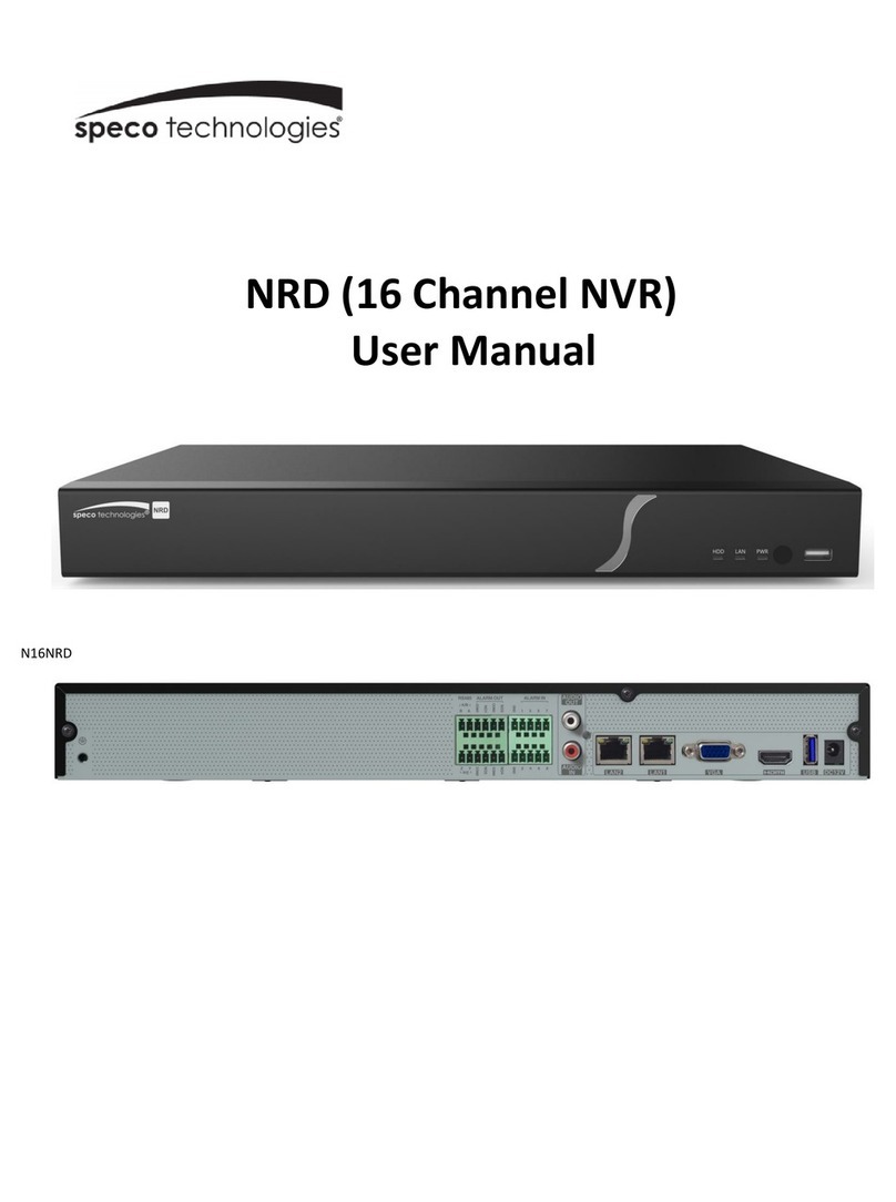
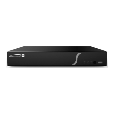
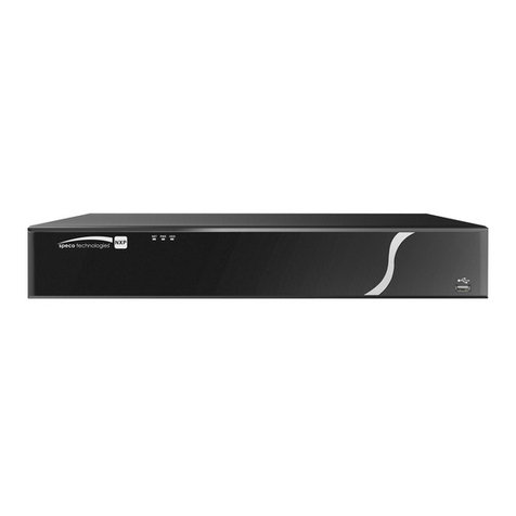
Speco NVRP4 User manual

NVRP4
User’s Manual
Aug. 2011

FCC NOTICE
This device complies with Part 15 of the FCC Rules. Operation is su ject to the following two conditions:
(1) this device may not cause harmful interference, and (2) this device must accept any interference
received, including interference that may cause undesired operation.
Federal Communications Commission Statement
NOTE- This equipment has een tested and found to comply with the limits for a Class A digital device,
pursuant to Part 15 of the FCC Rules. These limits are designed to provide reasona le protection against
harmful interference in a residential installation. This equipment generates uses and can radiate radio
frequency energy and, if not installed and used in accordance with the instructions, may cause harmful
interference to radio communications. However, there is no guarantee that interference will not occur in a
particular installation. If this equipment does cause harmful interference to radio or television reception,
which can e determined y tuning the equipment off and on, the user is encouraged to try to correct the
interference y one or more of the following measures:
Reorient or relocate the receiving antenna.
Increase the separation etween the equipment and receiver.
Connect the equipment into an outlet on a circuit different from that to which the receiver is connected.
Consult the dealer or an experienced radio/television technician for help.
CE NOTICE
This product is herewith confirmed to comply with the requirements set out in the Council Directives on
the Approximation of the laws of the Mem er States relating to Electromagnetic Compati ility Directive
2004/108/EC.
Warning - This is a Class A product. In a domestic environment this product may cause radio
interference in which case the user may e required to take adequate measures to correct this
interference.
DISCLAI ER
No warranty or representation, either expressed or implied, is made with respect to the contents of this
documentation, its quality, performance, merchanta ility, or fitness for a particular purpose. Information
presented in this documentation has een carefully checked for relia ility; however, no responsi ility is
assumed for inaccuracies. The information contained in this documentation is su ject to change without
notice.
TRADE ARKS
All other products or corporate names mentioned in this documentation are for identification and
explanation purposes only, and may e trademarks or registered trademarks of their respective owners.
COPYRIGHT
All rights reserved. No part of this pu lication may e reproduced, transmitted, transcri ed, stored in a retrieval
system, or translated into any language in any form y any means without the written permission of the
manufacturer.
The mark of Crossed-out wheeled in indicates that this product must not e disposed of with your other household
waste. Instead, you need to dispose of the waste equipment y handing it over to a designated collection point for
the recycling of waste electrical and electronic equipment. For more information a out where to drop off your waste
equipment for recycling, please contact your household waste disposal service or the shop where you purchased
the product.
Battery Safety Information
- Store the atteries in a cool dry place.
- Do not dispose of used atteries in domestic waste. Dispose of atteries at special collection points or return to point
of sale if applies.
- Remove the atteries during long periods of non-use. Always remove exhausted atteries from the remote control.
Battery leakage and corrosion can damage this remote control, dispose of atteries safely.
- Do not mix old and new atteries.
- Do not mix different types of atteries: alkaline, standard (car on-zinc) or rechargea le (nickel-cadmium).
- Do not dispose of atteries in a fire. The atteries may explode or leak.
- Never short circuit the attery terminals.

WARNING
TO REDUCE RISK OF FIRE OR ELECTRIC SHOCK, DO NOT EXPOSE THIS
APPLIANCE TO RAIN OR MOISTURE
CAUTION
IF THERE IS ANY DAMAGE, SHORTAGE OR INAPPROPRIATE ITEM IN THE
PACKAGE, PLEASE CONTACT YOUR LOCAL DEALER. WARRANTY VOID FOR
ANY UNAUTHORIZED PRODUCT MODIFICATION.
NOTICE
- INFORMATION IN THIS DOCUMENT IS SUBJECT TO CHANGE WITHOUT
NOTICE.
- THE INFORMATION CONTAINED HEREIN IS TO BE CONSIDERED FOR
REFERENCE ONLY.

Table of Contents
Chapter 1 Introduction ....................................................................................... 1
1.1 Package Content ............................................................................................................ 1
1.2 Front Panel ..................................................................................................................... 2
1.3 Back Panel ..................................................................................................................... 2
1.4 Setting Up the NVR Unit ................................................................................................. 3
1.4.1 Connecting Devices ................................................................................................... 3
1.4.1.1 Clamping the power cord ........................................................................................ 4
1.4.2 Connecting the Audio, Sensor and Relay Device ....................................................... 5
Chapter 2 Operating the NVR unit ..................................................................... 6
2.1 First Time Using the NVR Unit ........................................................................................ 6
2.1.1 Using the Virtual Key oard ......................................................................................... 7
2.2 Familiarizing Yourself with the Buttons in Preview Mode ................................................ 8
2.2.1 Setting Up and Using the Emap ............................................................................... 10
2.2.1.1 To Set Up the Emap ............................................................................................. 10
2.2.1.2 To Use the Emap .................................................................................................. 10
2.2.2 Familiarizing Yourself with the Buttons in PTZ Camera Controller ........................... 11
2.2.2.1 Setup the IP PTZ Camera .................................................................................... 12
2.2.3 Using Event Log Viewer ........................................................................................... 13
2.3 Familiarizing Yourself with the Buttons in Play ack Mode ............................................ 14
2.3.1 To Segment and Save the Desired Portion of the Recorded Video .......................... 16
2.3.2 To Bookmark a Video Section .................................................................................. 16
2.3.3 Using the Event Search ........................................................................................... 18
Chapter 3 Customizing the NVR System ........................................................ 19
3.1 System Setup ............................................................................................................... 19
3.2 Camera Setup .............................................................................................................. 25
3.2.1 To Setup the IP Camera ........................................................................................... 25
3.2.2 To Setup Camera from the Remote DVR ................................................................. 29
3.3 Recording Setup ........................................................................................................... 30
3.4 Network Setup .............................................................................................................. 32
3.5 Schedule Setting .......................................................................................................... 35
3.6 Backup Setup ............................................................................................................... 36
3.6.1 Using QPlayer to Play ack Backup Video ................................................................ 37
3.6.2 To Cut and Save the Portion of the Recorded Video ................................................ 40
3.6.3 Using the Visual Search ........................................................................................... 40
3.6.4 To Search Using the Event Search .......................................................................... 41
3.6.5 To Search Using the Intelligent Search .................................................................... 42
3.7 Sensor Setting .............................................................................................................. 43
3.8 Relay Setting ................................................................................................................ 44
3.9 Alarm Setting ................................................................................................................ 45

3.10 User Setup .................................................................................................................... 49
Chapter 4 Using the USB Playback Console .................................................. 51
4.1 Recommended system requirements ........................................................................... 51
4.2 Installing the USB Play ack Console............................................................................ 51
4.3 Running the USB Play ack Console ............................................................................ 52
4.3.1 To Cut and Save the Portion of the Recorded Video ................................................ 54
4.3.2 Play ack DVR Recorded File from Hard Disk .......................................................... 55
4.3.3 Play ack Backup File(*.dvr) ..................................................................................... 56
4.3.4 To Backup Recorded File ......................................................................................... 57
Chapter 5 iEnhance .......................................................................................... 58
5.1 To Use iSta le ............................................................................................................... 59
Chapter 6 Using the Remote Programs .......................................................... 60
6.1 Familiarizing Yourself with the Buttons in We Viewer .................................................. 61
6.1.1 To Setup Remote System Setting ............................................................................ 63
6.1.1.1 System Setting ..................................................................................................... 63
6.1.1.2 Camera Setting ..................................................................................................... 64
6.1.1.3 Record Setting ...................................................................................................... 67
6.1.1.4 Network Setting .................................................................................................... 69
6.1.1.5 Alarm Setting ........................................................................................................ 71
6.2 Familiarizing Yourself with the Buttons in We Viewer PTZ ........................................... 76
6.3 Familiarizing Yourself with the Buttons in Remote Console .......................................... 77
6.3.1 To Setup Remote Console Setting ........................................................................... 78
6.3.2 Familiarizing Yourself with the Buttons in PTZ Camera Controller ........................... 79
6.4 Using the Remote Play ack ......................................................................................... 80
6.4.1 Familiarizing Yourself with the Buttons in Local Play ack ........................................ 81
6.4.1.1 To Cut and Save the Wanted Portion of the Recorded Video ............................... 83
6.4.2 Familiarizing Yourself with the Buttons in RealTime Play ack ................................. 84
6.4.3 Familiarizing Yourself with the Buttons in Download and Play ack .......................... 86
Chapter 7 Using Mobile Device to Access NVR Server ................................... 87
7.1 Using PDAViewer to Access NVR Server ..................................................................... 87
7.1.1 To install PDAViewer thru ActiveSync ....................................................................... 87
7.1.2 To install PDAViewer from the Internet ..................................................................... 87
7.1.3 To Use the PDAViewer ............................................................................................. 89
7.1.4 To Play ack in PDAViewer ....................................................................................... 90
7.2 Using JavaViewer to Access NVR Server ..................................................................... 91
7.2.1 To install JavaViewer from the NVR Server .............................................................. 91
7.2.2 To Use the JavaViewer............................................................................................. 92
7.3 Using iPhone to Access Remote NVR Server .............................................................. 93
7.3.1 Download the SpecoPC Application ......................................................................... 93
I. Download through the PC..................................................................................... 93
II. Using iPhone to Download ................................................................................... 94
7.3.2 Using the SpecoPC Application ................................................................................ 94

Chapter 8 Web Tools ........................................................................................ 96
8.1 Dispatch Server ............................................................................................................ 96
8.1.1 To Run Dispatch program:........................................................................................ 96
8.2 Remote Setup ............................................................................................................... 97
8.2.1 To Add NVR server ................................................................................................... 97
8.2.2 To Setup Remote System Setting ............................................................................ 98
8.2.2.1 System Setting ..................................................................................................... 98
8.2.2.2 Camera Setting ..................................................................................................... 99
8.2.2.3 Record Setting .................................................................................................... 102
8.2.2.4 Network Setting .................................................................................................. 104
8.2.2.5 Alarm Setting ...................................................................................................... 106
8.3 Remote Backup .......................................................................................................... 110
8.3.1 To ack up the recoded data from the NVR server: ............................................... 110
Appendix A Registering Domain Name ............................................................................... 113

1
Chapter 1 Introduction
NVRP4 rings you the newest version of a true Network Video Recorder. With its compact size, it
provides 4 channel video and audio inputs and supports full range of IP cameras from all major
manufactures worldwide, accepting H.264, MPEG4 and MJPEG video streaming formats.
1.1 Package Content
(1)
(2)
(3)
(4)
(5)
(6)
(7)
(8)
(9)
(1) NVRP4 unit
(2) Software CD (User Manual included)
(3) Quick User Guide
(4) USB optical mouse
(5) Power Adapter
(6) Power Cord
(7) Screws for hard disk installation
(8) Clamp (see Chapter 1.4.2.1 for installation)
(9) Warranty card
i
If there is any damage, shortage or inappropriate item in the package contents, please contact your local
dealer.

2
1.2 Front Panel
Name Function
(1) NVR Power LED Light when the unit is power on
(2) HDD LED Indicate the hard disk running state. Light is on when the HDD is running
(Read/Write)
(3) IR Sensor Receive signal from the remote control to operate the unit
(4) USB 2.0 Port For flash drive/DVD-ROM connection
(5) Network 1 Indicator Indicate the status of network 1 (Port LAN 1)
(6) Network 2 Indicator Indicate the status of network 2 (Port LAN 2)
1.3 Back Panel
Name Function
(1) 2 x USB 2.0 ports For USB key oard, mouse, and other USB device connections.
(2) VGA Out Output the video signal to a CRT or LCD monitor
(3) Audio In/Out - Audio In: Input the audio signal from audio input device such as microphone
- Audio Out: Output the audio signal to a audio out device such as speaker
i
The audio input/output device has its own power supply where necessary.
(4) Sensor In Support 4 sensor devices
(5) Alarm Out Support 1 relay device (Relay: 1A @ 125VAC / 30VDC)
(6) Giga it LAN 2 port - To connect the switch of your network for internet connection, remote accessing,
and connection of IP camera.
- LAN 2 support Static, DHCP, or PPPOE mode.
(7) e-SATA port For connecting external RAID
(8) Giga it LAN 1 port - LAN connection only ut default assign as a DHCP service port. User also can
connect the IP camera through the Ethernet ca le.
-
LAN 1 supports Static or DHCP mode.
(9) Power utton Press it to power on the NVR unit.
(10) 12V DC Power ca le connection
(11) Clamp hole For clamp plug-in to clamp the power cord (see Chapter 1.4.2.1)
(12) Lock hole For locking the NVR unit to avoid NVR unit een taken.

3
1.4 Setting Up the NVR Unit
1.4.1 Connecting Devices
The ack panel of the NVR unit, user can connect 4 sensor devices, 1 alarm device, audio input/output
device and an external HDD storage device. Two Giga it LAN ports are provided to support the alance
of the network andwidth for IP camera connection and remote accessing. The USB ports can connect
the mouse and key oard for more easily to operate NVR server.
Follow the illustration elow to make the connection:
i
Both LAN ports can e used for connecting with IP camera and remote access.

4
1.4.1.1 Clamping the power cord
User can use the clamp that is included in the package to clamp the power cord to prevent the power cord
from sliding out.
Clamp
Power cord

5
1.4.2 Connecting the Audio, Sensor and Relay Device
The Sensor, Alarm, and audio port ena le you to connect 4 sensor inputs, 1 relay output, and 1 audio in
and 1 audio out device. Just connect the external sensor, relay, and audio in/out device pin directly to the
pinhole.
Check the ta le elow and locate which pinhole is assigned to sensor input, relay output, and audio
in/out.
The signal from the sensor (i.e. infrared sensors, smoke detectors, proximity sensors, door sensors, etc.)
is eing transmitted to the unit and this triggers the system to respond and send signal to relay device
(i.e., alarm, telephone etc).
Audio in and out pinhole:
Pin # Definition
1 Audio input signal
2 Audio Ground signal
3 Audio output signal
4 Audio Ground signal
Sensor and Alarm pinhole:
Pin # Definition
5 Sensor 1 signal
6 Sensor 1 Ground signal
7 Sensor 2 signal
8 Sensor 2 Ground signal
9 Sensor 3 signal
10 Sensor 3 Ground signal
11 Sensor 4 signal
12 Sensor 4 Ground signal
13 Alarm signal
14 Alarm signal

6
Chapter 2 Operating the NVR unit
2.1 First Time Using the NVR Unit
1. Connect the mouse to the USB port located at front panel of the NVR unit.
2. Using the mouse and virtual key oard (see also Chapter 2.1.1) to operate the NVR system.
3. Power on the NVR unit.
4. For security purposes, the NVR system would require you to enter User ID and Password efore it
can e accessed. (If this is the first time, enter the default ID [admin] and password [admin]).
Preview User Interface
5. Formatting the hard disk.
a. Click Setup and enter the password
. Click System → Add
c. Select the hard disk from device list and select Format type
d. Click Format utton to start formatting
e. When formatting is done, click OK.
6. Setup the correct date and time.
a. Click Setup and enter the password
. In Time section, click Setting utton of System Time.
c. Select the date and adjust the time, and then, click OK.
7. Connect the IP camera.
a. Click Setup → Camera
. Select camera channel and type of camera – IP Camera
c. And then, ena le the camera
d. Click IP Setting
e. Ena le Protocol, and then, select protocol, mode, video format, and channel of IP camera.
f. Enter IP address or URL of IP camera.
g. Enter ID and password if IP camera’s access authority is required.
h. Click OK.

7
i. Repeat step 7 to connect to another IP camera.
2.1.1 Using the Virtual Keyboard
User can use the Virtual Key oard when the key oard is not availa le. Just click or right-click on the
screen to call out the virtual key oard. For uppercase, click Caps utton. To exit, click Esc.

8
2.2 Familiarizing Yourself with the Buttons in Preview
ode
Name Function
(1) Exit Call up the Logout dialog ox.
In the logout dialog ox, you may do the following:
- Reboot: To restart the NVR system. It is required to enter the password
- Power OFF: To shutdown the NVR system.
- Login: Using different ID to login to NVR system.
- Cancel: To close the logout dialog.
(2) Split Screen Mode Select from 2 different split screen types to view all the cameras or one camera on a
single screen. It also allows you to switch and view different camera num er.
When user is in single screen mode, user can right-click and drag a square on the
area you want to enlarge the view. Right-click on the screen again will return to the
normal view.
(3) Record Start/stop video recording.
(4) EMap Display the map in each area, and the location of camera/ sensor/ relay and the
warning (see also Chapter 2.2.1).
(5) Network Ena le/disa le remote system access. This feature allows you to access NVR server
from a remote location via internet connection. The default is disa led.
(6) Setup Configure the system settings (see also Chapter 3)
(7) PTZ To call out the PTZ control panel (see also Chapter 2.2.2)
(8) Preview Switch to Preview mode. This allows you to view live camera display.
(9) Play ack Switch to Play ack mode. This allows you to view the recorded video file. (See also
Chapter 2.3).

9
Name Function
(10) Status ar Display the recoding date, time and hard disk space of NVR unit.
(11) Camera ID Show the num er of cameras that are eing viewed. When you are in single screen
mode, click the camera ID num er to switch and view other camera.
(12) Snapshot Capture and save the screen shot in *.jpg format.
(13) Event log Show the record of activities that take place in the system. (see also Chapter 2.2.3)
(14) AutoScan Start/Stop video screen cycle switch.
(15) Full screen View in full screen. To return, press the right utton of the mouse or ESC on the
key oard or click the arrow icon.
Click to exit from
full screen mode
When you switch to full screen in multiple-screen mode, Left click to toggle to only
display one of the video in the multiple-screen mode or all.
(16) Alarm Alert and display warning information.
(17) Virtual Key oard If the key oard is not availa le, you may use the virtual key oard.

10
2.2.1 Setting Up and Using the Emap
Emap can hold up to 8 maps in *.jpg format. You may locate the camera, sensor and relay on the map.
2.2.1.1 To Set Up the Emap
1. Click Emap.
2. When the Emap screen appears, click the area num er (1 to 8 uttons) on where you want to insert
the map.
3. Click Load ap to insert the map. When the open dialog ox appears, locate and select the map and
click Open.
4. When the inserted map appears on the Emap screen, click Edit. You may now drag and drop the
camera, sensor, and relay icons to its place on the map. Icons on the map can e relocated anywhere.
If you are going to relocate the icon on the map to other area, you need to drag the icon to the lack
pane at the ottom of the Emap screen and then switch to the area on where you want to locate the
icon. To ring all the icons ack to the lack pane at the ottom of the Emap screen, click Reset Icon.
5. When you are done, click Save utton to save the new setting. To exit Emap screen, click Close.
2.2.1.2 To Use the Emap
1. Click Emap.
2. In the Emap screen, click the camera icon to switch on the area where the camera is located on the
map and to display the video at the upper right corner of the Emap screen. At the lower right corner of
the Emap screen, it lists all the warning messages.
3. To view different Emap, click Emap num er utton (1 ~ 8).
4. Click Close to exit Emap screen.

11
2.2.2 Familiarizing Yourself with the Buttons in PTZ Camera
Controller
(2)
(1)
(1
1)
(3)
(4)
(5)
(6)
(7)
(8)
(9) (10)
Name Function
(1) Setup Configure PTZ cameras.(see also Chapter 2.2.2.1)
(2 Close Exit PTZ camera controller.
(3) AutoPan Operate the PTZ cameras automatically ased on the selected camera group preset
position num er.
(4) Focus +/- Adjust the focus manually to produce clear image.
(5) Zoom +/- Zoom in and out the image.
(6) Direction uttons
Adjust and position the focal point of the PTZ camera.
(7) Camera ID pane Display the PTZ camera num er that is eing operated.
(8) Save Camera
preset position
Save the PTZ camera preset position num er. Select the camera and click the preset
position num er and save it.
(9) Camera lens
speed controller Adjust the moving speed of the PTZ camera lens.
(10) Camera preset
position num er Move the PTZ camera to the preset point.
(11) Group AutoPan Select to automatically operate PTZ camera in group.

12
2.2.2.1 Setup the IP PTZ Camera
When IP PTZ camera has een successfully connected to the NVR system, user can use the PTZ
function directly without any configuration. To make connection of IP PTZ camera, please refer to Chapter
3.2.1.
In PTZ camera panel, user can setup the preset position of the camera. The num er of preset positions is
dependent on the IP PTZ camera that the user has connected. User can refer to the user’s manual of the
IP PTZ camera to find out the num er of the preset positions that are supported.
Please follow the elow steps to configure the preset position.
1. On Preview User Interface, select the channel that is an IP PTZ camera connection.
2. Click PTZ utton from Preview User Interface and PTZ control panel will show up.
3. In the PTZ control panel, using the arrow utton to adjust the position of IP PTZ camera.
4. And then, click Setup (see also Chapter 2.2.2). The Preset Settings window will show.
5. Select the Preset Number to assign a num er for the PTZ camera current position. And then, click
Save to save the setting.
6. Set the DwellTime for how long the PTZ camera stays in that position efore it moves to the next
one.
7. Repeat step 3 to 6, if you want to save another preset position.
8. Restore AutoPan Time: set a time period for restoring auto path function after the PTZ camera has
een moved manually. Mark the check ox and set the time period in second.
9. Click OK to complete the setting.

13
2.2.3 Using Event Log Viewer
Show the record of activities that take place in the system.
1. Click the Event Log utton on NVR system main interface. The Event log viewer window will show up.
2. Select the Date to view.
3. To filter the records, select and click the select utton to display Event, System, Operation, Network
or All.
4. Use the scroll utton to go next, previous, first, or last page ( , , , )of event list.
5. To find event log y keyword, enter keyword in Find Text column and click Search.
6. The events list which display on the screen can e saved as text file format. To save the events list,
click Save utton.

14
2.3 Familiarizing Yourself with the Buttons in Playback
ode
To switch in Play ack mode, click Playback utton at the lower right corner of Preview mode user
interface.
Name Function
(1) Split Screen
Mode
Select from 2 different split screen type to play ack the recorded video file of all cameras
or one camera on a single screen. When user is in single screen mode, user can
right-click and drag a square on the area to enlarge the view. Right-clicking on the screen
again will return to the normal view.
(2) Progress ar Shows the progress of the file eing played. You may move the ar to seek at any location
of the track.
(3) Hour Buttons Select and click to play ack the recorded video file on the specific time frame.
i
The Hour uttons represent the time in 24-hour clock. The lue ar on top of the hour utton indicates
that there is a recorded video file on that period of time. While the red ar indicates that you are currently
viewing the recorded video file.
(4) Play ack
Control Buttons
From left to right order:
Begin: Go ack to the eginning of the recorded video file.
Previous: Go ack to the previous frame.
Slower: Play the recorded video file at the reduce speed from 64x, 32x, 16x, 8x, 4x, 2x,
1x, 1/2x, 1/4x.
Rewind: Wind ack the recorded video file.
Pause: Briefly stop playing the recorded video file.
Play: Play the recorded video file.
Faster: Play the recorded video file at the speed of 2x, 4x, 8x, 16x, 32x, or 64x.
Next: Go to the next frame.
End: Go to the end of the recorded video file.
Other manuals for NVRP4
2
Table of contents
Other Speco Network Hardware manuals
Popular Network Hardware manuals by other brands

JDS Uniphase
JDS Uniphase ValidatorPRO-NT, Cu user guide

Avadesign
Avadesign avaControl-100 Installation and user guide

Cisco
Cisco ONS 15200 Series Installation, setup & user manual

AMX
AMX NetLinx NetModules NXS-NMS quick start guide

Nexcom
Nexcom FTA 5180 Series user manual

CommScope
CommScope RUCKUS SmartZone 300 Quick setup guide