Spectra POWERBOX 12A5 User manual

MANUAL
REVISION 1 - JANUARY 2019
SPECTRA POWERBOX 12A0
SPECTRA POWERBOX 12A5

2Spectra GmbH & Co. KG
sales@spectra.de
Sales Office Austria
sales@spectra-austria.at
Spectra (Schweiz) AG
sales@spectra.ch
MANUAL SPECTRA POWERBOX 12A0 / 12A5
PUBLISHER
Spectra GmbH & Co. KG
Mahdenstr. 3
D-72768 Reutlingen
Phone +49 (0) 7121 1432-10
Fax +49 (0) 7121 1432-190
E-Mail spectra@spectra.de
Web www.spectra.de
This document is protected by copyright.
It is illegal to copy, duplicate, reproduce, translate as an extract or otherwise.
- The information and references contained in the User’s Manuals are subject to technical changes that principally
occur due to continuous further development of the product lines of Spectra GmbH & Co. KG..
- Spectra GmbH & Co. KG. does not assume liability for any misprints or inaccuracies in this user manual.
- Spectra GmbH & Co. KG. advises that this user manual only contains general explanations of technical procedu-
res and instructions.
- Spectra GmbH & Co. KG. advises that this user manual will be continuously updated due to technical changes
and that the manual only reflects the technical status available at the time of print.
COPYRIGHT
Intel®is a registered trademark of the Intel®Corporation, USA
Windows®is a registered trademark of the Microsoft Corporation
Any further trademarks contained herein are the property of their respective owners.
REVISION: 1
DATE OF EDITION: 10.01.2019
MANUAL ARTICLE NUMBER: 153771

Spectra GmbH & Co. KG
sales@spectra.de
Sales Office Austria
sales@spectra-austria.at
Spectra (Schweiz) AG
sales@spectra.ch 3
MANUAL SPECTRA POWERBOX 12A0 / 12A5
INHALTSVERZEICHNIS
1. Introduction........................................................4
1.1 Packing list............................................................4
1.2 Options & accessories....................................4
1.3 Product description..........................................5
1.4 Function..................................................................5
1.5 Application............................................................5
1.6 Illustrations ...........................................................5
2. Important information .............................6
2.1 Safety instructions............................................ 6
2.2 CE qualification..................................................6
2.3 Transport.................................................................7
2.4 Cleaning..................................................................7
2.5 Disposal & recycling........................................7
3. Installation...........................................................8
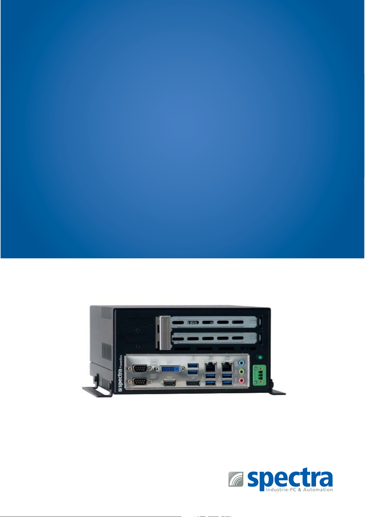
3.1 Power supply........................................................8
3.2 Display connection...........................................8
3.3 System expansions...........................................8
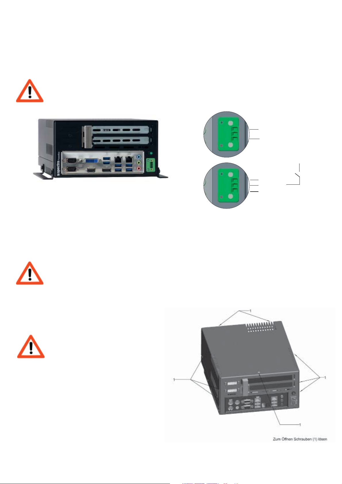
3.3.1 Accessing the device...................................8
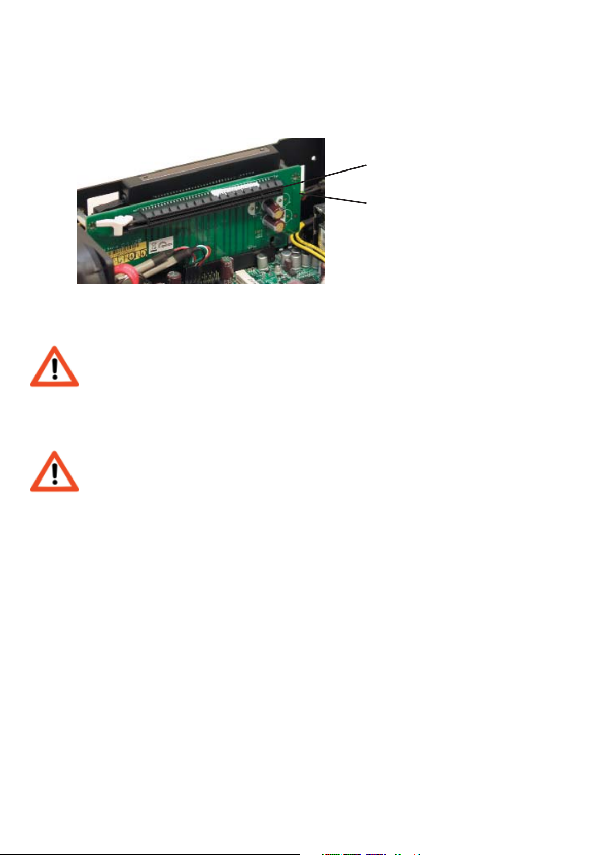
3.3.2 Installation of a plug-in card.................9
3.4 Installation guidelines.................................... 9
4. Implementing.................................................10
4.1 Operating elements & ports....................10
4.2 Configuration....................................................10
4.3 BIOS settings.....................................................10
4.4 Operating system installation.................10
4.5 Driver installation...........................................10
5. Ownership & data protection .........11
5.1 Bios-Setup ..........................................................11
6. Problem solving & tips..........................11
6.1 Operating display is dark..........................11
6.2 Device turns itself off...................................11
6.3 Display becomes dark .................................11
6.4 Display is faulty...............................................11
6.5 USB-device cannot be recognised ......12
6.6 Time and date are faulty............................ 12
6.7 BIOS basic settings........................................12
6.8 Device reboots.................................................12
7. Key combinations.......................................12
7.1 BIOS request .....................................................12
7.2 Hotkey...................................................................12
8. Power Ignition module.......................... 13
9. Technical data ................................................15
9.1 Ports.......................................................................15
9.2 Mechanical data.............................................16
9.3 Environment conditions.............................19
9.3.1 Operating conditions...............................19
9.3.2 Storage conditions....................................19
10. Quality & support....................................19
11. Warranty & service.................................20
11.1 Returns process (RMA)............................20
11.2 Service address.............................................20

4Spectra GmbH & Co. KG
sales@spectra.de
Sales Office Austria
sales@spectra-austria.at
Spectra (Schweiz) AG
sales@spectra.ch
MANUAL SPECTRA POWERBOX 12A0 / 12A5
1. INTRODUCTION
1.1 PACKING LIST
The device is delivered with the following components:
-usermanual
- power supply, power cable
-driver-CD
-mountingbrackets
1.2 OPTIONS & ACCESSORIES
- Up to 2 removable drive bays for 2,5“ HHD or SSD (optional, instead of 2 x PCI/PCIe)
- Graphics card upon request max. 50 Watt
- Art. 142302 AMD FirePro W2100/2GB | PC card, Graphics, PCIe, SLPHL, 2DP(4K), 26W
- Art. 152146 PNY Nvidia Quadro P1000/4GB | PC card, Graphics, PCIe, SLPHL, 4mDP/DP, 47W
- CPU: (instead of Core™i5-7440EQ (CM238 chipset) 2,9 GHz, or Xeon®(CM238 chipset) E3-1505Mv6)
-Intel
®Core™i7-7820EQ (CM238 chipset) Quad Core 3,0 GHz
-Intel
®Core™i3-7100E (HM175 chipset) Dual Core 2,9 GHz (no RAID)
- more upon request
- alternative SSD/Hard drives: (instead of NVMe M.2 SSD of basic systems) 2,5" SSD upon request
-Mini-PCIe(express):
- WLAN 54 Mbps, 802.11 a/b/g/n
- others upon request
-Misc.options:
- Rack assembly bracket, on the side
- VESA 100 Display Montage-Kit
- Operating system Microsoft®Windows®10 64-bit
- Operating system Linux Fedora 64-bit
- Operating system Ubuntu 64-bit
- More upon request
- Extension of warranty to 36 months

Spectra GmbH & Co. KG
sales@spectra.de
Sales Office Austria
sales@spectra-austria.at
Spectra (Schweiz) AG
sales@spectra.ch 5
MANUAL SPECTRA POWERBOX 12A0 / 12A5
1.3 PRODUCT DESCRIPTION
Performance characteristics:
Construction:
- extremely lightweight, robust aluminium chassis
- easy mounting
Cooling system:
- Processor cooling via heat pipe
- System cooling by an extremely quiet system fan with a high MTBF
- High system stability
1.4 FUNCTION
can differ depending on the selected options
- Integrated in chipset, ALC892 HD (mic-in, Line-out, AUX (rear)
- 2 x USB2.0 (front), 6 x USB 3.0 (rear)
- 4 x COM (2 x rear, 2 x front)
- 1 PCIe (x16) or optional 2 x PCIe(x8) (for cards max. 175 mm long / 49 W)
- 1 mPCIe or 1 mSATA, 1 x M.2 2280 M-Key
- 2 x Giga-LAN Interface, (10/100/1000Mbps)
1.5 APPLICATION
The device is suitable for the following application areas:
Multi-media, controlling, communikation, data acquisition, measurement and testing technology, visualization.
1.6 ILLUSTRATIONS
Explanation of the pictograms
Warning !
Failure to comply may lead to health impairment, loss of appliance efficiency or data loss
Tip!
Tips und supplementary information for daily work

6Spectra GmbH & Co. KG
sales@spectra.de
Sales Office Austria
sales@spectra-austria.at
Spectra (Schweiz) AG
sales@spectra.ch
MANUAL SPECTRA POWERBOX 12A0 / 12A5
2. IMPORTANT INFORMATION
- The user manual should be read thoroughly before operating the appliance.
- Each individual that will be working with the device should adhere to this manual, and especially the safety
instructions, at alltimes.
- The relevant rules and regulations for accident prevention at the place of installation, should be observed at all
times.
- The device should only be used in accordance with this user manual.
- The compliance with legal requirements and device specifications must be observed if the appliance has been
enhanced.
- Modifications and maintenance repairs should only be executed by authorised individuals from Spectra GmbH &
Co. KG.
- Modifications and alterations of and to the device are not permitted. Spectra GmbH & Co. KG takes no responsi-
bility for the resulting damages.
- The newest user-manuals and documents are valid.
The specified technical data supplied by us, was determined by us using our methods and facilities: characteristics
will only bewarranted based on this. The testing and suitability for the intended use of the end-user, or consequent-
ly the application environ-ment/conditions, are incumbent on the user. Spectra GmbH & Co. KG. will not assume
liability in this case.Always make a backup copy of the data on an external storage medium (CD-R, disks) after
updating. Claiming compensationbecause of data loss and subsequent damage due to the loss is ruled out.
2.1 SAFETY INSTRUCTIONS
- Please check that the mains voltage conforms with the specifications of the device.
- Always observe the installation guidelines.
- Always observe the safety instructions in the section „Service and Support“
- Always observe the environment conditions.
- Attention: some components can be warm to the touch during and after operation.
- In order to power off completely, it is not sufficient to only switch off the device. Always plug out the mains
supply.
- Some components can also be at risk of being electrostatic. Please observe the reference notes in the section
„System Expansions“
- Please do not insert any objects into the interior of the device through the slits and openings. This could lead to
short-circuiting or even result in fire.
- If the user disregards the safety instructions, Spectra GmbH & Co. KG. cannot be held liable for accidents due to
the disregard.
2.2 CE QUALIFICATION
This device complies with the EMC Requirements and the EN 60950 Safety Norm.

Spectra GmbH & Co. KG
sales@spectra.de
Sales Office Austria
sales@spectra-austria.at
Spectra (Schweiz) AG
sales@spectra.ch 7
MANUAL SPECTRA POWERBOX 12A0 / 12A5
2.3 TRANSPORT
The device should only be transported in the original packaging or in alternative packaging
which offers enough protection against impact, blows and humidity.
Please observe the following when transporting:Major temperature and humidity fluctuations can cause conden-
sation of the interior of the device, that can lead to short-circuiting.Please wait until the device has adopted its’
surrounding temperature before switching on.
2.4 CLEANING
Turn off the device and pull out the plug.
- Clean the casing with a dry cloth or alternatively a damp cloth if the soiling is too intense.
- Do not use abrasive power or synthetic thinner for cleaning.
- Please always pay attention that no liquids infiltrate the chassis.
- Only trained personnel are permitted to clean the interior.
2.5 DISPOSAL & RECYCLING
Always observe the applicable regulations for the correct disposal.Batteries and accumulators do not belong in
the household waste, these will be taken back free of charge by the manufacturer,dealer or his commissionaires.
The battery regulation obligates the end-user of used batteries, to bring these back to the dealer or to the returns
locations set upby the public waste disposal authorities.

8Spectra GmbH & Co. KG
sales@spectra.de
Sales Office Austria
sales@spectra-austria.at
Spectra (Schweiz) AG
sales@spectra.ch
MANUAL SPECTRA POWERBOX 12A0 / 12A5
3. INSTALLATION
3.1 POWER SUPPLY
Only use the approved power supplies for this device!
Each cable connection must be tested before starting the system.
One has to ensure that all voltages and signals have the appropriate value.
ATX Mode: 9~36 V / Ground
Ignition Mode: 9~36V / Ground with Power Ignition Signal
3.2 DISPLAY CONNECTION
Always observe the EMC Regulations.
Only use high quality feed cables that have high shielding effectiveness.
3.3 SYSTEM EXPANSIONS
3.3.1 ACCESSING THE DEVICE
Pull out the plug before opening.
Appropriate safety measures
should be taken to avoid
electrostatic discharges.
1 . The screws (1) on the side of the rear panel
must be released in order to open the device.
2. The top cover of the casing can subsequently
be lifted off.
Illustration can vary depending on the configuration
9~36 VDC
9~36 VDC
0 Volt
0 Volt
Ignition
ATX Mode
Ignition Mode
+
-
+
-
+

Spectra GmbH & Co. KG
sales@spectra.de
Sales Office Austria
sales@spectra-austria.at
Spectra (Schweiz) AG
sales@spectra.ch 9
MANUAL SPECTRA POWERBOX 12A0 / 12A5
3.3.2 INSTALLATION OF A PLUG-IN CARD
1. Turn off the Spectra PowerBox and pull out the plug
2. Remove the top cover of the casing as described in section 3.3.1
3. Please remove the slot-shield of the desired plug-in slot.
4. Insert the PCI-Card in the plug-in slot.
Do not tilt the PCI-Card while inserting!
3.4 INSTALLATION GUIDELINES
It is absolutely necessary to pay attention to the correct positional arrangement,
due to the usage of the heat-pipe cooling system.
Incorrect installation will lead to the overheating of the CPU!
- The device can be positioned as a stand-alone device or mounted using the optional mounting brackets.
- The device must not be exposed to direct solar radiation or be operated near heat sources.
- The device must not be mounted outdoors.
- The device must not be used in an explosion-risk area.
- The device is not designed for mobile applications.
- The device should only be operated in a low-dust environment. The air ventilation vents cannot be additionally
safeguarded (e.g. filter) against the infiltration of dust.
- Vents and slots serve to provide air ventilation for the device. Do not cover these vents at any time as it could
result in overheating.
- When positioning the device, please take heed that the air vents are not obstructed.
4
3

10 Spectra GmbH & Co. KG
sales@spectra.de
Sales Office Austria
sales@spectra-austria.at
Spectra (Schweiz) AG
sales@spectra.ch
MANUAL SPECTRA POWERBOX 12A0 / 12A5
4. IMPLEMENTING
4.1 OPERATING ELEMENTS & PORTS
Start-up possibilities:There are diverse start-up possibilities other than via the on-switch. E.g. Switching-on after a
power-failure. These can be regulated in BIOS. (see board manual)
4.2 CONFIGURATION
In order to install an operating system, drives need to be assigned and booting sequences need to be defined in the
BIOS settings.(see board manual)
4.3 BIOS SETTINGS
Set the BIOS values ( based on the board manual) according to your needs. When an operating system has been
pre-installed, par-ticular basic settings have already been distinguished.If any problems occur, please go to “Prob-
lem Solving and Tips” or respectively the board manual.
A BIOS update isn’t usually necessary.
All requests for required BIOS-Updates should be placed with our support team.
4.4 OPERATING SYSTEM INSTALLATION
Please observe that various operating systems may have varied hardware support. Therefore e.g. the maximum
supported primary storage and the maximum HDD size may be deviant, depending on the operatingsystem in use.
Software Installation by the Manufacturer
Spectra GmbH & Co. KG. normally provides the device with a pre-installed operating system and drivers.In this
case, the user only has to install his applications and configure the operating system based on his needs.
Self-Implementation of the Software
Standard software is usually supplied on a CD-ROM. Software can be installed by implementing the USB port with
an externaldrive. In order to boot, one usually has to change the boot sequence in the BIOS settings. Please see
section BIOS Settings fordetailed information.
4.5 DRIVER INSTALLATION
The drivers for the integrated board periphery are to be found on the webseite of the board manufacturer.
Manufacturer: iBASE
Board: MI992
https://www.ibase.com.tw/english/ProductDetail/EmbeddedComputing/MI992

Spectra GmbH & Co. KG
sales@spectra.de
Sales Office Austria
sales@spectra-austria.at
Spectra (Schweiz) AG
sales@spectra.ch 11
MANUAL SPECTRA POWERBOX 12A0 / 12A5
5. OWNERSHIP & DATA PROTECTION
5.1 BIOS-SETUP
The BIOS settings can be protected against unauthorised access by a password.
6. PROBLEM SOLVING & TIPS
6.1 OPERATING DISPLAY IS DARK
Please check if the feeder is plugged in properly.
Turn off the device completely again and wait a few seconds.
Then plug the device back in and turn it back on.
6.2 DEVICE TURNS ITSELF OFF
- Check and see if the device has been installed in the correct position. (see Installation Guidelines)
- It’s possible that other components have been installed that cause an unacceptably high switch-on current.
Remove these components and try again. Always observe the boot-dialogue on the display.
- The CPU cooler may not be positioned accurately.(transport damage) The internal protective circuit causes the
shutting-down
Plug-out the device from the supply voltage and check if the CPU cooler is in
the correct position
6.3 DISPLAY BECOMES DARK
- The display is dark (screen saver or suspend mode is activated)
Press any keyboard key. Respectively, the screen saver mode or the energy saving mode
need to be switched off. Please check in the “Help” of you OS for further information.
- The input-port has been chosen incorrectly.
Check the settings in the OSD Menu of your display.
6.4 DISPLAY IS FAULTY
Please check the plug and sockets. When the picture content is correct but the colours are
illustrated incorrectly, this is an indication that the DVI connector is tilted or respectively
bent/distorted contacts

12 Spectra GmbH & Co. KG
sales@spectra.de
Sales Office Austria
sales@spectra-austria.at
Spectra (Schweiz) AG
sales@spectra.ch
MANUAL SPECTRA POWERBOX 12A0 / 12A5
6.5 USB-DEVICE CANNOT BE RECOGNISED
- Some USB devices need a high switch-on current.
Re-boot the computer while the USB-device is plugged-in.Alternatively, use a USB hub
with an external electrical supply
6.6 TIME AND DATE ARE FAULTY
When the time and date are being shown incorrectly, you can either change the data in BIOS or in your OS. If the
time and dateare continuously shown incorrectly then the battery needs to be changed by the service department
6.7 BIOS BASIC SETTINGS
If there is an interference in the BIOS while booting or if the wrong BIOS has been chosen, this can lead to the
default BIOS para-meters being loaded in order to protect the hardware.
The BIOS settings then need to be changed according to the application requirements.
6.8 DEVICE REBOOTS
- In the case that the device reboots when booting the operating system, please check the BIOS-settings.
- The system also reboots in the set time interval if Watchdog has been activated in the Bios, until an application
triggers the Watchdog.
7. KEY COMBINATIONS
7.1 BIOS REQUEST
One can request the BIOS by pressing the DELETE key.
Press the DELETE key accurately timed, before Windows has loaded.
7.2 HOTKEY
(optional: depending on model configuration)

Spectra GmbH & Co. KG
sales@spectra.de
Sales Office Austria
sales@spectra-austria.at
Spectra (Schweiz) AG
sales@spectra.ch 13
MANUAL SPECTRA POWERBOX 12A0 / 12A5
8. POWER IGNITION MODULE
80.2 mm
14.6 mm
23.1 mm
1.5 mm
45.0 mm
160.0 mm
7.3 mm
145.4 mm
F1
1
2
4
1
3
CN2
J6
10
CN1
20
11
J1
J3
J2
J4
J5
26.8 mm
Max. torque
0.35 Nm
J4 Jumper attached=On
A B C D Mode O-delay at all rails on 5VSB Hard-o
Off Off Off Off P0 PSU mode
On Off Off Off P1 5 sec + 1 min auto-latch 1 min
Off On Off Off P2 5 sec + 1 min auto-latch 2 h
On On Off Off P3 5 sec + 1 min auto-latch Never
Off Off On Off P4 30 sec + 1 min auto-latch 2 h
On Off On Off P5 30 sec + 1 min auto-latch Never
Off On On Off P6 30 min Never
On On On Off P7 3 h Never
Off Off Off On P8 10 min 1 h
On Off Off On P9 15 min 2 h
Off On Off On P10 1 h 75 min
On On Off On P11 5 sec + 1 min auto-latch 1 min
Off Off On On P12 5 sec + 1 min auto-latch 10 min
On Off On On P13 5 sec + 1 min auto-latch 1 min
Off On On On P14 5 sec + 1 min auto-latch 10 min
J1 input +
Flat plug 6.3 x 0.8 mm or equal
J3 Ignition/Start (not in mode P0)
Flat plug 6.3 x 0.8 mm or equal
J2 input –
Flat plug 6.3 x 0.8 mm or equal
J4 Jumper block (incl. Jumper)
J5 Remote ON/OFF
for motor vehicle amplifier
JS-6001-02 2 P or equal
J6 Mainboard ON/OFF
JS-6001-02 2 P or equal
F1 Fuse 20 A
Output connector
CN1
ATX, SATA, HD, FD power connections
CN2
P4/EPS power connection
For more information, please see the
„Application Note“ at www.bicker.de
5 VSB Hard-off: In case battery voltage falls
below the listed „Switch Off“ voltage for 1 minute
or longer, the DC 161 W automatically shuts
down (deep discharge protection):
Mode P1-P10
Switch Off @ 11.0 V – Start @ 12.0 V
Mode P11-P12
Switch Off @ 10.5 V – Start @ 10.8 V
Mode P13-P14
Switch Off @ 10.7 V – Start @ 11.3 V
Switch Off @: Separation of the application
from 5VSB during the Hard-off time when the
voltage drops below the specified value for
1 minute or longer.
Start @: Required voltage to (re-) start system.
AutoLatch: With this function the PC‘s power
is not disconnected within the first 60 seconds
to guarantee a secure start and shutdown of
the PC, e.g. during a very short ignition.
The following modes for ignition functions are selectable by jumper:
Tolerance: ±0.5 m
m

14 Spectra GmbH & Co. KG
sales@spectra.de
Sales Office Austria
sales@spectra-austria.at
Spectra (Schweiz) AG
sales@spectra.ch
MANUAL SPECTRA POWERBOX 12A0 / 12A5
Vin
Ignition
5VSB
MB ON/OFF (J6) 200mS
ÆÅ
POWER ON/OFF (PSon)
3,3V
|
5V
|
12V
|
-12V
POWER GOOD
200mS
ÆÅ
250mS
ÆÅ
10mS
ÆÅ 20mS
ÆÅ
T1
ÆÅ T6 ÆÅ
Deep discharge protection
T5 ÆÅ
T4
ÆÅ
T3
ÆÅ
T2
ÆÅ
The following modes are selectable by jumper J4 (Jumper attached=On)
ModeT1T2T3
T4
MB ON/OFF
OFF-DELAY
T5
5VSB
HARD-OFF
T6
DEEP DISCHARGE
PROTECTION
P1 1 sec 5 sec 1 sec 5 sec + 1 min auto-latch 1 min 1 min
P2 1 sec 5 sec 1 sec 5 sec + 1 min auto-latch 2 hour 1 min
P3 1 sec 5 sec 1 sec 5 sec + 1 min auto-latch Never 1 min
P4 1 sec 5 sec 1 sec 30 sec + 1 min auto-latch 2 hour 1 min
P5 1 sec 5 sec 1 sec 30 sec + 1 min auto-latch Never 1 min
P6 1 sec 5 sec 1 sec 30 min Never 1 min
P7 1 sec 5 sec 1 sec 3 hour Never 1 min
P8 1 sec 5 sec 1 sec 10 min 1 hour 1 min
P9 1 sec 5 sec 1 sec 15 min 2 hour 1 min
P10 1 sec 5 sec 1 sec 1 hour 75 min 1 min
P11 1 sec 5 sec 1 sec 5 sec + 1 min auto-latch 1 min 1 min
P12 1 sec 5 sec 1 sec 5 sec + 1 min auto-latch 10 min 1 min
P13 1 sec 5 sec 1 sec 5 sec + 1 min auto-latch 1 min 1 min
P14 1 sec 5 sec 1 sec 5 sec + 1 min auto-latch 10 min 1 min
TIMING DIAGRAM

Spectra GmbH & Co. KG
sales@spectra.de
Sales Office Austria
sales@spectra-austria.at
Spectra (Schweiz) AG
sales@spectra.ch 15
MANUAL SPECTRA POWERBOX 12A0 / 12A5
9. TECHNICAL DATA
9.1 PORTS
Illustration can vary depending on the configuration
2 COM HDMI 3 Audio
Reset
DC-in
DVI-D 6 USB3.0
2 RJ45
DP
2 COM
2 USB2.0

16 Spectra GmbH & Co. KG
sales@spectra.de
Sales Office Austria
sales@spectra-austria.at
Spectra (Schweiz) AG
sales@spectra.ch
MANUAL SPECTRA POWERBOX 12A0 / 12A5
9.2 MECHANICAL DATA
External Dimensions (without mounting rail): width 200 mm
height110mm
depth 250 mm
Illustration can vary depending on the configuration

Spectra GmbH & Co. KG
sales@spectra.de
Sales Office Austria
sales@spectra-austria.at
Spectra (Schweiz) AG
sales@spectra.ch 17
MANUAL SPECTRA POWERBOX 12A0 / 12A5
External Dimensions (with front mounting rail): width 240 mm
height110mm
depth250mm
Article n° 114959 Mounting rail_left for rackmount
Article n° 114960 Mounting rail_right for rackmount
Illustration can vary depending on the configuration

18 Spectra GmbH & Co. KG
sales@spectra.de
Sales Office Austria
sales@spectra-austria.at
Spectra (Schweiz) AG
sales@spectra.ch
MANUAL SPECTRA POWERBOX 12A0 / 12A5
External Dimensions (with table mounting rail): width 240 mm
height110mm
depth250mm
Illustration can vary depending on the configuration

Spectra GmbH & Co. KG
sales@spectra.de
Sales Office Austria
sales@spectra-austria.at
Spectra (Schweiz) AG
sales@spectra.ch 19
MANUAL SPECTRA POWERBOX 12A0 / 12A5
9.3 ENVIRONMENT CONDITIONS
9.3.1 OPERATING CONDITIONS
Temperature : 0°C - 45°C Environement in Hybridmode (Add-on cards max. <50 W)
Temperature change : max. 10°C / 30 min
Relative humidity : 10 - 90 %
relative humidity : 700 - 1100 hPa
Condensation Generation : non condensing
9.3.2 STORAGE CONDITIONS
Temperaturbereich : -20°C - 60 °C Environement
Relative humidity : 0 - 90 %
Relative humidity : 280 - 1100 hPa
Kondensat-Bildung : nicht kondensierend
10. QUALITY & SUPPORT
Quality is our most important objective. Our Quality Assurance tests each component from the electronic parts to
the completedsystem, competently and comprehensively.
Our products are distinguished not only because of their maximum profitability and dependability, but because of
our comprehensive all-round service.
- Spectra GmbH & Co. KG. wants you to be satisfied and will support you in every detailed question of your
product development.
- We offer qualified and expert user consultation by capable sales and distribution engineers.
- If you have any questions about the utilisation of the device or if any difficulties arise during usage, do not
hesitate to contact our support team, who will help in every way they can.
You will need to have the following readily available for inquiries:
- The product number of your device
- The serial number of your device

20 Spectra GmbH & Co. KG
sales@spectra.de
Sales Office Austria
sales@spectra-austria.at
Spectra (Schweiz) AG
sales@spectra.ch
MANUAL SPECTRA POWERBOX 12A0 / 12A5
11. WARRANTY & SERVICE
Spectra systems are service-friendly und easily maintainable.
Terms and Conditions of Warranty:
Failure to comply with the safety regulations and important notes leads to Spectra Computersysteme being
absolved from its war-ranty obligation. Components that because of their limited lifespan due to being exposed to
exceptional wear and tear, are not included in theextended warranty (above and beyond the statutory warranty).
No warranty claim can be made if the device is used beyond the given specifications or not according to the given
regulations.If maintenance checks have been designated at particular intervals, these must be kept to.
11.1 RETURNS PROCESS (RMA)
It is possible that the components or modules of the devices can be damaged or destructed due to considerable
impacts that ariseduring transport.
Our original packaging was especially designed for the device and therefore guarantees the compliance with the
general transportregulations for a safe device delivery.
Hence please only utilise the original packaging for any further transport or for returns. This packaging can be
requested if required.
We cannot accept liabilty for transport damage in any other event.
Before sending any malfunctioning device back to Spectra GmbH & Co. KG., please follow the steps below:
Contact our customer services department and request an RMA number or alternatively go to our homepage www.
spectra.de and you can request a number there.
- Write the RMA number clearly legible on the package you will be sending us.
- Specify a contact person in case of further inquiries
- Pack the device in the original cardboard box and packaging.
11.2 SERVICE ADDRESS
Spectra GmbH & Co. KG
Mahdenstr. 3
D-72768 Reutlingen
Phone +49 (0) 7121 1432-10
Fax +49 (0) 7121 1432-190
E-Mail spectra@spectra.de
Web www.spectra.de
This manual suits for next models
1
Table of contents
Other Spectra Industrial PC manuals

Spectra
Spectra PowerBox 3000A Series User manual

Spectra
Spectra Powerbox 110 Series User manual

Spectra
Spectra POWERTWIN P12i5-6300UR User manual

Spectra
Spectra PowerBox 500 Series User manual

Spectra
Spectra POWERBOX 100-J19 RTE User manual

Spectra
Spectra POWERBOX 410 Series User manual

Spectra
Spectra PowerBox 3000E Series User manual

Spectra
Spectra PowerBox 5000C Series User manual