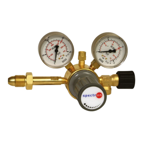
Spectron FS4 User manual

User manual
Controller
FS4
05/2020

Table of contents Spectron Gas Control Systems GmbH
ii GES_FS4_0520
Table of contents
1 Introduction.................................................................................................................................................. 4
2 Description................................................................................................................................................... 5
2.1 Intended use ......................................................................................................................................... 5
2.2 Misuse .................................................................................................................................................. 5
2.3 Identification / label ............................................................................................................................... 5
2.4 Environment.......................................................................................................................................... 5
2.4.1 Temperatures............................................................................................................................. 5
2.4.2 Degree of cleanliness ................................................................................................................ 6
2.5 Standards and laws .............................................................................................................................. 6
3 Safety............................................................................................................................................................ 7
3.1 Basic information on the safety instructions ......................................................................................... 7
3.2 Safety instructions ................................................................................................................................ 8
3.3 Emergencies and safety devices .......................................................................................................... 10
3.3.1 Emergency stop (emergency shut-off)....................................................................................... 10
3.4 Qualification of the operating and maintenance personnel................................................................... 10
4 Design and function .................................................................................................................................... 12
4.1 Design................................................................................................................................................... 12
4.2 Functional description........................................................................................................................... 13
4.3 Technical data ...................................................................................................................................... 14
4.4 Boundaries and interfaces .................................................................................................................... 14
5 Installation.................................................................................................................................................... 15
5.1 General information .............................................................................................................................. 15
5.2 Electrical connection............................................................................................................................. 15
5.2.1 Digital inputs .............................................................................................................................. 16
5.2.2 Analogue inputs ......................................................................................................................... 17
5.2.3 Relay outputs ............................................................................................................................. 17
5.3 Pneumatic connection .......................................................................................................................... 18
6 Commissioning............................................................................................................................................ 20
6.1 Preparations for commissioning ........................................................................................................... 20
6.2 Procedure for commissioning ............................................................................................................... 20
7 Operation...................................................................................................................................................... 21
7.1 General information on operation ......................................................................................................... 21
7.2 Configuration ........................................................................................................................................ 21
7.2.1 Language options ...................................................................................................................... 23
7.2.2 User management ..................................................................................................................... 24
7.2.3 System configuration ................................................................................................................. 25
7.2.4 Real Time Clock......................................................................................................................... 27
7.2.5 Analogue inputs ......................................................................................................................... 28
7.2.6 Digital inputs .............................................................................................................................. 31
7.2.7 Label valves ............................................................................................................................... 33
7.2.8 Assignment of the analogue inputs............................................................................................ 33
7.2.9 Tare setting ................................................................................................................................ 34
7.3 Commissioning a valve......................................................................................................................... 35
7.4 Putting the valve in standby mode........................................................................................................ 36
7.5 Automatic switchover............................................................................................................................ 37


Spectron Gas Control Systems GmbH Table of contents
GES_FS4_0520 iii
7.5.1 Recovery function ...................................................................................................................... 39
7.6 Manual mode ........................................................................................................................................ 40
7.7 Alarm history......................................................................................................................................... 43
7.8 Decommissioning ................................................................................................................................. 43
8 Maintenance, cleaning and repairs............................................................................................................ 44
8.1 General information on maintenance.................................................................................................... 44
8.2 Regular maintenance work and cleaning.............................................................................................. 45
9 Repair ........................................................................................................................................................... 46
9.1 General information on repair work ...................................................................................................... 46
9.2 Troubleshooting and fault rectification .................................................................................................. 47
10 Dismantling and disposal ........................................................................................................................... 48
10.1 General information on dismantling ...................................................................................................... 48
10.2 Disposal ................................................................................................................................................ 49

1 | Introduction Spectron Gas Control Systems GmbH
4 GES_FS4_0520
1 Introduction
This user manual is the original user manual for the Controller FS4 from Spectron Gas Control
Systems GmbH (Fritz-Klatte-Str. 8, D-65933 Frankfurt), referred to as Spectron.
The Controller FS4 constitutes an incomplete machine in the context of the Low Voltage Direct-
ive 2014/35/EU. The Declaration of Conformity is stored in the system documentation.
The user manual is intended to facilitate correct and safe operation for the operating firm, and to
warn against misuse. It is intended for the qualified personnel and the operator of the facility.
WARNING
Incorrect operation
Incorrect operation of the system, e.g. due to instruction errors, can lead to personal injury or
damage to the system.
a) Access to the user manual by the operating and maintenance personnel must be absolutely
ensured at all times.
b) A copy of the system documentation including the user manual must therefore be kept
either on the system or in a suitable and accessible location.
This user manual contains information protected by copyright law. It must not be photocopied,
reproduced, translated or copied onto data carriers, either in full or in part, without prior author-
isation. Spectron retains all further rights.

Spectron Gas Control Systems GmbH Description | 2
GES_FS4_0520 5
2 Description
2.1 Intended use
The intended use of the Controller FS4 is the control of up to 4 pneumatic valves. These can be
individually configured or used for up to 2 automatic changeovers between 2 gas sources each.
The permissible gas types and pressure ranges are each specified on the label (see "Identifica-
tion / label").
The Controller is not permitted to be used in an explosion hazard zone.
To be able to use the Controllers as intended, all persons working with it must comply with the
specifications of the relevant user manual.
The area in which hazards can occur when used as intended is the area around the Controllers.
The danger zone changes depending on the system status and use.
2.2 Misuse
Any improper use constitutes misuse. Controllers may only be used for the specified gases and
in the specified pressure range. Controllers with electrical components without marking accord-
ing to EU Directive 2014/34/EU may not be used in an explosion hazard zone.
Furthermore, the following operating conditions are regarded as misuse:
– Use for gases in their liquid phase
– Failure to carry out inspection and maintenance work
– Pressurisation in reverse (opposite to the flow direction)
– Operation with gases that are not specified on the label
– Operation outside the permissible technical limit values
– Failure to heed and comply with any applicable legal regulations and other provisions
– Non-observance of the user manual
– Failure to heed the information on the label and in the product data sheet
2.3 Identification / label
The label is located on the on the body of the Controller.
The label provides the following details:
Details Example
Manufacturer Spectron Gas Control Systems GmbH
Article description FS4
Article number 66QE0017
2.4 Environment
2.4.1 Temperatures
Normal temperatures expected in a production area are assumed when operating the system:
0°C to +45°C. On storage, temperatures between -20°C and 60°C are permissible.
The air humidity must be below 60 % rel. humidity to prevent condensation. The operating tem-
perature depends on the gas used.

2 | Description Spectron Gas Control Systems GmbH
6 GES_FS4_0520
2.4.2 Degree of cleanliness
Access to the system and to the escape and rescue routes must not be blocked.
The product should be kept clean (dust-free).
For the control air, compressed air must be used of at least class 5 according to ISO 8573-1 or
nitrogen (minimum quality 6.0).
2.5 Standards and laws
The design and construction of the controller is subject to the following standards and direct-
ives:
2014/35/EU Low Voltage Directive
2014/30/EU EMC Directive
DIN EN ISO 12100:2010 Safety of Machinery
DIN EN 60204-1 Safety of Machinery - Electrical equipment of
machines – Part 1: General requirements regu-
lates general specifications and recommenda-
tions as a sub-standard of EN 60204 Safety of
Machinery
Various additional laws, regulations and guidelines must be complied with when handling pres-
surised gases. Find out about the laws, regulations and guidelines that apply in your location.
BetrSichV Betriebssicherheitsverordnung (Industrial
health and safety ordinance)
ProdSG Produktsicherheitsgesetz (Product Safety Law)
TRBS 1111 Technische Regeln Betriebssicherheit (Tech-
nical Regulations on Operational Safety)
DGUV Regulation 1 German Trade Association Principles of Pre-
vention
DGUV Regulation 3 Electrical installations and equipment

Spectron Gas Control Systems GmbH Safety | 3
GES_FS4_0520 7
3 Safety
3.1 Basic information on the safety instructions
The product complies with the recognised technical regulations. Nevertheless, knowledge of the
media used and their dangers as well as basic knowledge of the pressure control panel are pre-
requisites for safe and accident-free operation.
The user manual must be read and understood by every user. Instruction must be documented
in writing.
The safety instructions are to be regarded as a supplement to the applicable accident preven-
tion regulations and laws. Existing accident prevention regulations and laws must be observed
in all cases.
NOTICE
Hazards from the operating environment of the system can lead to injuries to persons.
a) No changes may be made to the system which result in a change in function.
b) It is not possible to outline and cover in this manual all hazards arising from the environment
or unforeseeable operating conditions of the system.
In the Safety Instructions chapter:
– Users are informed regarding hazards, residual risks and measures for risk reduction.
– The presentation of the safety instructions and the symbols is explained.
– Basic safety instructions to be observed in general are listed. Specific safety instructions are
listed in the relevant chapters.
DANGER
DANGER indicates an imminent danger. If not avoided, death or extremely serious injur-
ies will result.
WARNING
WARNING indicates a potential imminent danger. If not avoided, death or serious injury
could result.
CAUTION
CAUTION indicates a potentially imminent danger. If not avoided, minor or moderate in-
jury could result.
NOTICE
NOTICE indicates a potentially harmful situation. If not avoided, the system or property in
its vicinity could be damaged.

3 | Safety Spectron Gas Control Systems GmbH
8 GES_FS4_0520
3.2 Safety instructions
DANGER
Voltage
The components of the control and the connections are under voltage. There is a danger of
death on contact.
a) Only allow work in which the control unit must be opened to be carried out by trained spe-
cialist personnel (electricians).
b) Only perform work in which the control unit must be opened when the power supply is
switched off.
c) The five safety rules according to DIN VDE 0105 are to be observed:
ðDisconnect from the mains
ðSecure against reconnection
ðVerify that the system is dead
ðCarry out earthing and short circuiting
ðProvide protection from adjacent live parts
DANGER
Defective product
A defect on the product can result in unforeseeable operating conditions. Persons may be in-
jured.
a) The product may only be operated in technically perfect condition in compliance with all
chapters of the user manual.
b) Environmental protection laws and safety regulations must be observed.
WARNING
Maintenance
Due to a fault condition, e.g. due to insufficient maintenance, parts of the product can be unex-
pectedly energised. This may result in electric shocks.
a) The electrical installation is to be tested regularly. Loose connections and defective cables
must be rectified immediately.
b) Observe the maintenance intervals and maintenance regulations in this operating manual.
c) Observe the maintenance intervals and maintenance guidelines from the manufacturer and
the applicable guidelines.
d) Components may only be replaced by spare parts of the same design. The specifications of
the component manufacturers must be complied with during installation.
WARNING
Noise emission
When working on pressurised pneumatic supply, significant noise emission can occur. Acute
and chronic loss of hearing may result.
a) Never perform work on the pressurised pneumatic supply without hearing protection.
b) Only replace the silencers when the supply is unpressurised.

Spectron Gas Control Systems GmbH Safety | 3
GES_FS4_0520 9
WARNING
Displacement of atmospheric oxygen
In the event of inert gas leaks, displacement of atmospheric oxygen may occur. Danger of suf-
focation!
a) The operator must ensure adequate ventilation and airing in all rooms with gas installations
and monitor the oxygen content.
WARNING
Cross-contamination
Cross-contamination of the control air with process gases can result in the control unit being
damaged.
a) Ensure that cross-contamination of the control air line is prevented.
WARNING
Repairs
If the product is not used as intended, unpredictable operating conditions may occur. Serious
personal injuries are possible.
a) Repairs may not lead to a change in function. The system may not be tampered with or
modified.
b) Before each repair, the system must be depressurised and flushed through.
c) Repairs are only permitted to be carried out by trained persons.
WARNING
Working on the product
If an accident occurs when working on the product, there is a considerable risk of injury.
a) Never work on the product unattended or unannounced.
b) Observe the site safety rules and permission procedure.
CAUTION
Injury or damage in the event of incorrect assembly or disassembly
Special steps are required for assembly and disassembly work on the product. Personal injuries
and damage to the product are possible.
a) Assembly and disassembly work may only be carried out by the installation engineer or ap-
propriately skilled specialist companies and persons.
b) The product is not permitted to be re-used following disassembly. All components must be
disposed correctly.

3 | Safety Spectron Gas Control Systems GmbH
10 GES_FS4_0520
CAUTION
Static discharge
Static discharges can occur in the event of contact between the control unit and persons or
between parts of the electrical equipment. Injuries, shock responses and damage to the control
unit are possible.
a) Before commissioning, the operating firm must ensure that all electrical equipment is
provided with equipotential bonding (earthing).
b) The earthing function is to be tested on a regular basis. The intervals are specified by the
operating firm in its risk assessment.
NOTICE
Lighting
Incorrect switching actions or confusion can occur due to inadequate lighting.
a) Ensure sufficient lighting in accordance with the statutory regulations.
3.3 Emergencies and safety devices
The operational local safety regulations of the system operator, such as the alarm plan, fire
safety regulations and the escape and rescue plans, apply in all cases for the operation of the
Controller.
When handling gases, all specifications from the safety data sheets must be followed. Local
emergency services should be informed of the gases used at the site of the system.
In the event of mechanical damage, the product must be put into a safe operating condition.
3.3.1 Emergency stop (emergency shut-off)
When the emergency stop is actuated, all valves are closed and the power supply to the solen-
oid valves is interrupted.
3.4 Qualification of the operating and maintenance
personnel
The intended user group is the system operator (user of the system) and the system mainten-
ance personnel.
Every person working on the system must be familiar with the functions and dangers associated
with the overall system. Instruction on the system is to be documented in writing.
Maintenance and repair work should only be carried out by specially trained personnel.
All operators, as well as personnel who regularly enter the area, must be trained on a minimum
of the following topics:
– Alarm rules at the site and conduct in the event of malfunctions and leaks
– Basic functions of the product
– User manual
– System documentation incl. manufacturer documentation
– Position of the safety devices

Spectron Gas Control Systems GmbH Safety | 3
GES_FS4_0520 11
– Safety data sheets on the process gas used
– Personal protective equipment
In addition, operators must have the requisite physical and mental skills to operate and maintain
the equipment.
Persons who do not meet this requirement (e.g. visitors), must not remain alone in the overall
system.
Operating personnel must use appropriate personal protective equipment for the activities to be
performed and the associated environmental hazards. The operational instructions and the spe-
cifications of the employers' liability insurance associations and the safety data sheets must be
complied with.

4 | Design and function Spectron Gas Control Systems GmbH
12 GES_FS4_0520
4 Design and function
4.1 Design
Diagram of the FS4 controller
5
1
76
2
4
3
Position Designation
1 Emergency stop
2 Red LED
3 Yellow LED
4 Green LED
5 Main switch
6 Pneumatic input
7 Pneumatic outputs
The complete enclosure assembly has an environmental rating of IP65. On the front is an emer-
gency stop button [1] and on the rear there is an on/off switch [5]. Internally there is an addi-
tional input for an external emergency stop. This can be deactivated as necessary. When one of
the two shutdown options is activated, all valves are closed and the power supply to the solen-
oid valves is interrupted.
For the operating firm, there are 10 digital inputs (NC or NC contacts) as well as 8 analogue in-
puts (4-20mA) available for the FS4 controller. There is also a voltage-free relay output for re-
porting the valve status. The connection to all input and output devices is established via cable
glands on the underside of the body.
The controller power supply is provided via a three-wire mains cable. The FS4 controller is sup-
plied with a 5 m long, permanently wired cable that can be cut to the desired length. The con-
troller is secured internally with a circuit breaker of characteristic B.

Spectron Gas Control Systems GmbH Design and function | 4
GES_FS4_0520 13
Diagram of the FS4 controller
7
6
9
3
2
5
8
1
4
Position Designation
1 8 fuses for analogue inputs
2 Main fuse
3 Circuit breaker
4 External emergency stop input
5 0V connection
6 Digital inputs
7 16 relay outputs
8 Analogue inputs
9 24V connection
4.2 Functional description
The intended use of the Controller FS4 is the control of up to 4 pneumatic valves. These can be
individually configured or used for up to 2 automatic changeovers between 2 gas sources each.
The control unit is designed to allow 3 different programs to be selected by the user:
The first program is intended for 2 independent gas supply systems, each of which has 2 gas
sources, which switch automatically when one side is empty. This ensures uninterrupted gas
supply. This can be carried out using valves located before or after the pressure regulating unit.
The second program is intended for 1 independent supply system which has 2 gas sources that
switch over automatically when one side is empty. This ensures uninterrupted gas supply. This
can be carried out using valves located before or after the pressure regulating unit. In addition,
2 valves can be controlled for an emergency or source shutdown.
The third program is intended for 4 valves for emergency or source shutdown. When valves are
configured as independents, they can be enabled/disabled from the configuration screen.
All controller actions which require an input from an operator are protected by a dual layer pass-
word system that allows up to five trained operators to have different operational access via
their own personal Identification Number (PIN).
Configuration of the controller type, digital and analogue inputs and alarm settings are all set via
the GUI.

4 | Design and function Spectron Gas Control Systems GmbH
14 GES_FS4_0520
4.3 Technical data
NOTICE
The technical data can be taken from the data sheet for the relevant product. If this is not avail-
able, you can view and download it at www.spectron.de.
The maximum input and output pressures and the gas type are given on the identification or la-
bel.
4.4 Boundaries and interfaces
The scope of supply includes the product as described in the "Design" chapter. The transfer
points to the control air and power supply are the connections on the controller.
The following areas and functions have not been included in the scope of supply from Spectron:
– other systems, lines and installations of the overall system
– Supply of auxiliary media (compressed air or purge gas)
– Power supply
– Lighting

Spectron Gas Control Systems GmbH Installation | 5
GES_FS4_0520 15
5 Installation
5.1 General information
CAUTION
Injury or damage in the event of incorrect assembly or disassembly
Special steps are required for assembly and disassembly work on the product. Personal injuries
and damage to the product are possible.
a) Assembly and disassembly work may only be carried out by the installation engineer or ap-
propriately skilled specialist companies and persons.
b) The product is not permitted to be re-used following disassembly. All components must be
disposed correctly.
The controller is to be mounted to a suitable wall or framework using four fixings with a max-
imum diameter of 4.8 mm. Once installed, the four red plastic covers should be fitted over the
screws to maintain the IP65 rating. The data sheet and the dimensional drawing are stored in
the manufacturer's documentation.
5.2 Electrical connection
DANGER
Voltage
The components of the control and the connections are under voltage. There is a danger of
death on contact.
a) Only allow work in which the control unit must be opened to be carried out by trained spe-
cialist personnel (electricians).
b) Only perform work in which the control unit must be opened when the power supply is
switched off.
c) The five safety rules according to DIN VDE 0105 are to be observed:
ðDisconnect from the mains
ðSecure against reconnection
ðVerify that the system is dead
ðCarry out earthing and short circuiting
ðProvide protection from adjacent live parts
The controller is shipped with a 5 metre hard wired cable which can be cut to the required
length. The controller is secured internally with a circuit breaker of characteristic B. All earth
wires are connected to the room earthing via the power supply.

5 | Installation Spectron Gas Control Systems GmbH
16 GES_FS4_0520
5.2.1 Digital inputs
Illustration1: Digital inputs
The digital input module (P1-16ND3) provides the connections for the digital sensor inputs. Di-
gital inputs of sensors and switches are directly connected to the terminals of the digital PLC in-
put module. The following information refers to the terminal designation (C1 to 16) of the mod-
ules (see figure above) and not to the designations on the terminals.
The terminals with red lines indicate the connections available for customer digital inputs. The
black lines are part of the system wiring and may not be removed or added. Digital input 12 is
optionally available for remotely switching off the horn. This means that 10 individual digital in-
puts are available which can be configured as normally open contacts or normally closed con-
tacts. The configuration and use of the digital inputs is described in the corresponding instruc-
tion manuals.
All sensors must be connected with a two-wire cable. This cable (max. diameter 6 mm) is
passed through one of the cable glands on the base of the unit and connected according to the
electrical connection diagrams. The polarity of the sensors must be checked before connection.
A short circuit when connecting a sensor results in one of the 24V control fuses being tripped.
One wire on the digital input is connected to a free terminal (2 to 11) on the PLC input module.
The other wire is connected to one of the free inputs of the common 24V connection.
The cover of the input module (P1-16ND3) can be unfolded for access to the terminals on the
connection. The screw version terminals require a 0.4 x 2.5 mm flat screwdriver to clamp the
wires. The wire end is stripped to a length of 9 to 10 mm and inserted into the connecting ter-
minal. The maximum permissible diameter of the stripped wires is 1.5 mm².
The 24V connection for digital inputs is as shown below.
Illustration2: Wiring scheme for digital inputs

Spectron Gas Control Systems GmbH Installation | 5
GES_FS4_0520 17
5.2.2 Analogue inputs
Illustration3: Analogue inputs and safety clip
The connections for the analogue inputs are connected directly to the module P1-08ADL-1. The
negative terminal of each analogue signal generator is connected to one of the I+-terminals of
the module. The positive terminal of the signal transmitter is connected to one of the 8 available
24V fuse terminals. Each terminal is secured with a 32mA glass fuse (20 x 5 mm).
All sensors must be disposed of professionally as hazardous waste. This cable (max. diameter
6 mm) is passed through one of the cable glands on the base of the unit and connected accord-
ing to the electrical connection diagrams.
5.2.3 Relay outputs
Illustration4: Relay outputs
The connections for the relay outputs are connected directly to the output module P1-16TR.

5 | Installation Spectron Gas Control Systems GmbH
18 GES_FS4_0520
C1 and relay outputs 1 to 8 are used by the controller and must not be otherwise assigned. C1
is disconnected from the network as soon as an emergency stop or remote shutdown signal is
active.
The wiring of terminals C2 and the associated relay outputs 9 to 16 are provided for the follow-
ing functions:
– C2: 24V power supply for relay outputs 9 to 16
– 9: free
– 10: External horn (NO)
– 11: Emergency shutdown (NC)
– 12: Warning signal (NC)
– 13: Status valve 1 (NO)
– 14: Status valve 2 (NO)
– 15: Status valve 3 (NO)
– 16: Status valve 4 (NO)
5.3 Pneumatic connection
DANGER
Intended use
Operation of the product with gases other than those specified or outside the limits may result in
dangerous reactions in the system. Incorrect use poses considerable risks to operating person-
nel and the environment!
a) Only use the product for gases for which it was designed.
b) Only use the product in the specified limit values for pressure and withdrawal quantity.
c) Usage for another type of gas or outside the limit values is prohibited and constitutes mis-
use.
WARNING
Noise emission
When working on pressurised pneumatic supply, significant noise emission can occur. Acute
and chronic loss of hearing may result.
a) Never perform work on the pressurised pneumatic supply without hearing protection.
b) Only replace the silencers when the supply is unpressurised.
WARNING
Displacement of atmospheric oxygen
In the event of inert gas leaks, displacement of atmospheric oxygen may occur. Danger of suf-
focation!
a) The operator must ensure adequate ventilation and airing in all rooms with gas installations
and monitor the oxygen content.

Spectron Gas Control Systems GmbH Installation | 5
GES_FS4_0520 19
WARNING
Cross-contamination
Cross-contamination of the control air with process gases can result in the control unit being
damaged.
a) Ensure that cross-contamination of the control air line is prevented.
The solenoid valves require a supply of clean dry air or nitrogen filtered to 10μm, at max. 5.5
bar. This is connected via a 4mm push-in fitting on the base of the device as indicated on the la-
bel. Any exhaust from the solenoid valves is vented internally and excess pressure build-up is
vented to atmosphere via an IP65 breather on the base of the unit.

6 | Commissioning Spectron Gas Control Systems GmbH
20 GES_FS4_0520
6 Commissioning
6.1 Preparations for commissioning
The controller may only be commissioned following installation at the place of use and connec-
tion of the control air and the electrical power supply.
The power supply and the electrical connections inside the housing must be checked before
commissioning. The controller must not be operated without a fuse, loose connections must be
tightened before commissioning.
Make sure that:
– the assembly has been correctly carried out,
– the controller is connected to the correct control air
– the control air supply is in operation and a pressure test for the control air has been per-
formed
– the circuit breaker is not tripped
6.2 Procedure for commissioning
Switch on the controller by switching the main switch.
Table of contents
Other Spectron Controllers manuals

Spectron
Spectron spectrocem LE81 User manual

Spectron
Spectron spectropur LE 71 User manual

Spectron
Spectron Spectrolab LM71 User manual

Spectron
Spectron Spectrocem FE 121 User manual

Spectron
Spectron spectrocom CRF62 User manual

Spectron
Spectron FE45 User manual

Spectron
Spectron spectropur LE 71 User manual

Spectron
Spectron Spectrotec LT2000 User manual

Spectron
Spectron spectrolab FM45 User manual

Spectron
Spectron Spectrotec LT71 User manual