Spectronics Corporation Spectroline TC-254R User manual

OPERATOR’S MANUAL
Fixed-Intensity
Ultraviolet Transilluminators
SPECTRONICS
CORPORATION
956 Brush Hollow Road, P.O. Box 483
Westbury, New York 11590
800-274-8888 • 516-333-4840
Fax: 800
-491-6868 •
516
-333-4859
www.spectroline.com
Manual No. 97048-4
Printed in U.S.A. Issued: September 2003
Recycled
Paper

2
WARNING
Please read instructions in this manual carefully before
operating your Spectroline®transilluminator. Never use
this equipment in any manner not specified in these
instructions because the protection provided by the
equipment may be impaired. We recommend using
Spectroline UV-absorbing protective eye and face wear. See
Replacement Parts and Accessories for model numbers. This eye
and face wear also improves contrast between the
fluorescent area and the background and eliminates
“blue haze” interference.
DANGER
Ultraviolet radiation emitted from this product. Avoid
exposure. ALWAYS WEAR PROTECTIVE CLOTHING. EXPOSURE
MAY CAUSE PREMATURE AGING OF THE SKIN AND CANCER.
ALWAYS WEAR PROTECTIVE EYEWEAR; FAILURE TO DO SO MAY
RESULT IN SEVERE BURNS OR LONG TERM INJURY TO EYE.
Never look directly into the lamp. Exposure can cause eye
and skin allergy and allergic reactions. Medications or
cosmetics may increase your sensitivity to ultraviolet
radiation. Consult physician before operating this product if
you are using medications or have a history of skin
problems or believe yourself especially sensitive to
sunlight.
FOR LABORATORY USE ONLY

3
INTRODUCTION
Spectroline ultraviolet transilluminators produce the high irradiance
needed to excite fluorescence in electrophoresis gels and thin
layer chromatograms. They are also ideal for use in forensic sci-
ence, pharmaceutical quality control, and much more. Each unit
offers high UV intensity, uniform irradiance and cool operation. They
feature a wide variety of filter sizes, rugged construction and simple
operation. All 312nm and 365nm models come with a special,
polymer-based diffusing screen that ensures excellent irradiance
uniformity at the filter surface and improves photographic quality.
These fixed-intensity ultraviolet transilluminators are available in
120V/60Hz, 230V/50Hz or 100V/50-60Hz versions.
MODEL WAVELENGTH FILTER SIZE EQUIPPED WITH
TC-254R 254nm 8 x 8 inch Six 15-watt UV-C tubes, cooling fan,
(20.3 x 20.3cm) automatic timer
TC-312R 312nm 8 x 8 inch Six 15-watt UV-B tubes, cooling fan,
(20.3 x 20.3cm) automatic timer, diffusing screen
TC-365R 365nm 8 x 8 inch Six 15-watt UV-A tubes, cooling fan,
(20.3 x 20.3cm) automatic timer, diffusing screen
TL-254R 254nm 8 x 16 inch Six 15-watt UV-C tubes, cooling fan,
(20.3 x 40.6cm) automatic timer
TL-312R 312nm 8 x 16 inch Six 15-watt UV-B tubes, cooling fan,
(20.3 x 40.6cm) automatic timer, diffusing screen
TL-365R 365nm 8 x 16 inch Six 15-watt UV-A tubes, cooling fan,
(20.3 x 40.6cm) automatic timer, diffusing screen
TR-254R 254nm 6 x 14 inch Six 15-watt UV-C tubes, cooling fan,
(15.2 x 35.6cm) on/off switch
TR-312R 312nm 6 x 14 inch Six 15-watt UV-B tubes, cooling fan,
(15.2 x 35.6cm) diffusing screen, on/off switch
TR-365R 365nm 9 x 13 inch Six 15-watt UV-A tubes, cooling fan,
(22.9 x 33.0cm) diffusing screen, on/off switch
TS-254R 254nm 6 x 6 inch Six 15-watt UV-C tubes, cooling fan,
(15.2 x 15.2cm) on/off switch
TS-312R 312nm 6 x 6 inch Six 15-watt UV-B tubes, cooling fan,
(15.2 x 15.2cm) diffusing screen, on/off switch
TS-365R 365nm 6 x 6 inch Six 15-watt UV-A tubes, cooling fan,
(15.2 x 15.2cm) diffusing screen, on/off switch

OPERATION
UNPACKING AND INSPECTION
1.Carefully unpack and inspect the transilluminator for possible
damage in shipment. If any damage is noted, immediately notify
the carrier and supplier before using the unit.
2.Save the shipping carton and packing materials for future storing
or shipping of the unit.
3.Connect the plug of the cord first to the fused power entry unit
and then to a power outlet that complies with the electrical
requirements specified on the unit’s label.
DESCRIPTION
1.Filter Transmits 254nm, 312nm and/or 365nm
wavelength UV radiations.
2.Filter Frame Steel frame supports glass filter. Four
screws allow easy access to change
tubes or filters.
3.Timer (TC and Serves as on/off power switch and allows
TL models)* presetting of UV exposure time.
4.On/Off Switch Controls power to the unit.
(TR and TS models)
5.Cooling Fan Maintains cool unit operation.
6.Air Vents Provide proper ventilation for UV tubes.
7.UV Tubes Provide UV illumination.
8.Diffusing Screen Eliminates light striations caused by the
contours of the tubes.
9.Fused Power Entry Unit Supplies power to the unit via the power
cord.
*Not Illustrated
4. On/Off Switch
8. Diffusing Screen
(under filter) 9. Fused Power Entry Unit
7. UV Tubes
(inside unit)
1. Filter
5. Cooling Fan
(inside unit)
6. Air Vents
(below unit)
2. Filter Frame
4

5
GENERAL FUNCTIONAL CHECKS
NOTE: To produce maximum fluorescent contrast, these tests should
be made in a darkened room or in conjunction with a Spectroline
UV viewing cabinet (see Spectroline UV Viewing Cabinets).
1.Activate the TR and TS models by pressing the ‘‘ON’’ switch.
Activate the TC and TL models by turning the timer knob to the
desired exposure time.
2.The UV tubes should become energized and a steady glow of
light should be evident across the filter area. The light may flicker
initially, especially if the unit is cold, but should stabilize after a few
seconds.
DIFFUSING SCREEN IN 312nm AND 365nm MODELS
All 312nm and 365nm models are equipped with a unique diffusing
screen attached to the underside of the UV filter. This screen
ensures excellent irradiance uniformity across the filter area and
eliminates light striations. These two features are especially impor-
tant in photographic applications.
NOTE: The diffusing screen lowers the overall UV intensity of the
312nm models by approximately 30%, while it reduces the overall
intensity of the 365nm models by approximately 25%. Therefore,
there may be instances when the operator will wish to remove it.
REMOVAL/REPLACEMENT OF DIFFUSING SCREEN
1.Remove the filter assembly as described in Replacing the Filter
Assembly.
2.Carefully place the filter assembly filter-side down on a flat, level
surface, making sure that it does not get scratched.
3.Remove the four screws and lift the diffusing screen off the filter
assembly. If the diffusing screen is going to be used again, store
the screen and screws.
4.Reinstall/replace the diffusing screen by centering its holes over
the screws protruding from the filter assembly. Be sure the metal
frame of the screen is facing toward the tubes (light source).
5.Tighten the four screws and reinstall the filter assembly on the
transilluminator.
WARNING
Observe UV safety precautions before turning on the unit.

UVT-150A UV-TRANSMITTING FILTER PROTECTOR
To facilitate cutting of gels without damage to the filter glass, the
UVT-150A UV-transmitting filter protector is available separately. This
accessory also protects the filter from damage caused by acci-
dentally dropping small objects on the transilluminator. In addition,
since buffer and ethidium bromide will not come in contact with
the filter, it eliminates clouding of the glass and high background
fluorescence.
To use, set the filter protector directly on the transilluminator’s filter
assembly. Then place the sample on the surface of the UVT-150A.
Please note that the filter protector cannot be used with short wave
UV transilluminators since it does not transmit 254nm.
UVC-250A HINGED UV-BLOCKING COVER
A convenient hinged UV-blocking cover is available as an acces-
sory. It adjusts to any angle from 0° to 180°, enabling the operator
to work on samples while providing eye and face protection. It also
protects the filter surface from damage caused by accidentally
dropping small objects on the transilluminator. This cover fits conve-
niently over electrophoresis gels and TLC plates.
To install the UVC-250A hinged UV-blocking cover, remove the
screws from the front of the transilluminator. Attach the two brack-
ets supplied with the cover to the front of the transilluminator with
the open slot facing up. Slip the cover into the slots of the brackets.
The screw in the center of each hinge assembly on the cover
adjusts to the proper hinge tension so the cover can be suspended
at any angle from 0° to 180°.
Fig. 1
Tension-Adjustment Screw
Mounting Screws on Cover
6

7
Fig. 2
SPECTROLINE UV VIEWING CABINETS
Spectroline UV viewing cabinets provide increased fluorescent
contrast of samples and eliminate the need for separate UV pro-
tection. The sample is placed on the transilluminator filter and safe-
ly observed through the UV-absorbing viewing window of the cab-
inet. The TC and TS model transilluminators are compatible with all
Spectroline UV viewing cabinets, while the TL and TR models can be
used with the CC-80, CL-150, CX-20/CX-21 and CX-50 cabinets.
PHOTOGRAPHIC DOCUMENTATION
Spectroline transilluminators may be used for photodocumentation
with the Polaroid DS-34, MP-4 and CU-5 research cameras or any
35mm SLR camera in conjunction with the Spectroline CC-80 or
CL-150 UV viewing cabinets. Specially designed Spectroline
camera adapters easily mount the cameras to the cabinets.
Additionally, the DS-34 can be used with a range of Spectroline
PhotoDoc™ camera hoods for photodocumentation directly on
the transilluminator filter surface.
The appropriate Spectroline camera adapter should be equipped
with a UV-barrier filter (such as Kodak Wratten 2A, 2B or 2E) to avoid
unwanted film exposure. When using the DS-34 camera with a
PhotoDoc hood, the Tiffen 22, 23A or 25 orange filter (or equivalent)
should be used. These filters attach directly to the DS-34 camera
and provide color correction as well as UV-barrier protection. When
using the DS-34 with a Spectroline camera adapter, the Tiffen filters
may also be used as an alternative to the Wratten filters.
WARNING
To reduce the risk of electric shock, disconnect
from power source before any servicing.

8
MAINTENANCE
Spectroline UV transilluminators are constructed of high-quality
materials and components. By providing reasonable care and fol-
lowing these instructions, the user can expect a long and useful life
from the transilluminator. Immediately clean all spilled materials
from the transilluminator and wipe dry. If necessary, moisten a cloth
with soap and water and clean the transilluminator. Do not use any
harsh chemical cleaners. Do not attempt to clean the unit while it
is plugged into a power source.
REPLACING THE FILTER ASSEMBLY
After considerable use, the filter on the 254nm or 312nm
transilluminators may solarize and require replacement.
If the UV-blocking cover accessory has been employed, it must be
removed from the brackets. Unscrew both brackets from the filter
assembly. Remove the four screws holding the filter assembly.
Unscrew the ground wire and the bracket above the interlocking
switch. Remove the diffusing screen (see Removal/Replacement of
Diffusing Screen) and set it aside.
Install the new filter assembly by reversing the above procedure.
Reattach the diffusing screen, the bracket covering the switch and
the ground wire. Tighten the four screws on the filter assembly and
reattach the two brackets for the UV-blocking cover.
REPLACING THE UV TUBES
To replace the ultraviolet tube(s), remove the four screws holding
the filter frame to the transilluminator housing. If visually inspecting
lit tubes, wear a Spectroline UVF-80 UV-absorbing face shield and
protective clothing. Check for cracked or malfunctioning tubes.
Replace a suspected malfunctioning tube with a new tube. If the
new tube performs properly, discard the old tube.
NOTE: Use a clean cloth or wear cotton gloves during servicing.
Contamination may result if the glass section of the UV tubes or the
metal reflector is touched directly. This will reduce the UV output.
After servicing, wipe the tubes clean with a pure solvent (such as
methanol) or mild detergent to eliminate contamination that could
cause damage.
Once all malfunctioning tubes are replaced, lower the filter frame
to its original (horizontal) position. Replace the four screws that hold
the filter frame to the housing.

TROUBLESHOOTING
If the transilluminator does not yield satisfactory results, follow the
procedures below before attempting to service the unit:
a. Review and comply with the instructions in the Operation section.
b. Check that the transilluminator is connected to a power source
and that the on/off switch or timer knob is positioned correctly.
c. Check that the fuse is operating properly. Use needlenose pliers
to remove the fuse drawer from the power entry unit. There is an
extra fuse in the 120V unit. Remove and discard the spent fuse
and replace it with the spare. The 230V unit has two active fuses
and a filter. Both fuses must be replaced. Use metric fuses for both
the 120V (2.5A F) and 230V (1.5A F) units.
If these steps do not yield satisfactory results, refer to the following
chart:
Symptom Probable Cause Cure
9
1. Low output from part
of filter area
UV tube(s) functioning
at substandard
intensity level
Replace tube(s)
2. Low uniform output
(short wave or
medium wave
transilluminators only)
a. Filter solarized a. Replace filter
assembly
b. UV tubes functioning
at substandard
intensity level
b. Replace tubes
c. Diffusing screen
solarized
(312nm and 365nm
models only)
c. Replace diffus-
ing screen
ENVIRONMENTAL CONDITIONS
The Spectroline fixed-intensity ultraviolet transilluminators are
designed to be safe under the following conditions.
• Indoor use;
• Altitude up to 2,000 m (6,562 ft.);
• Temperature 5°C to 40°C (41°F to 104°F);
• Maximum relative humidity 80% for temperatures up to 31°C
(88°F) decreasing linearly to 50% relative humidity at 40°C (104°F);
• Mains supply voltage fluctuations not to exceed ±10% of the
nominal voltage;
• Installation Category II;
• Pollution Degree 2.

ELECTRICAL SPECIFICATIONS AND REPLACEMENT PART NUMBERS
WAVE- FILTER
MODEL LENGTH TUBE ASSEMBLY VOLTS HZ AMPS FUSE
TC-254R UV-C BLE-1T155 2F808B 120 60 2.0 2.5A F
TC-254R/F; /FB UV-C BLE-1T155 2F808B 230 50 1.2 1.25A F
TC-312R UV-B BLE-1T158 3F808R 120 60 2.0 2.5A F
TC-312R/F; /FB UV-B BLE-1T158 3F808R 230 50 1.2 1.25A F
TC-365R UV-A BLE-1T151 2F883B 120 60 2.0 2.5A F
TC-365R/F; /FB UV-A BLE-1T151 2F883B 230 50 1.2 1.25A F
TL-254R UV-C BLE-1T155 2F816B 120 60 2.0 2.5A F
TL-254R/F; /FB UV-C BLE-1T155 2F816B 230 50 1.2 1.25A F
TL-312R UV-B BLE-1T158 2F816B 120 60 2.0 2.5A F
TL-312R/F; /FB UV-B BLE-1T158 2F816B 230 50 1.2 1.25A F
TL-365R UV-A BLE-1T151 2F168B 120 60 2.0 2.5A F
TL-365R/F; /FB UV-A BLE-1T151 2F168B 230 50 1.2 1.25A F
TR-254R UV-C BLE-1T155 2F614B 120 60 2.0 2.5A F
TR-254R/F; /FB UV-C BLE-1T155 2F614B 230 50 1.2 1.25A F
TR-312R UV-B BLE-1T158 2F614B 120 60 2.0 2.5A F
TR-312R/F; /FB UV-B BLE-1T158 2F614B 230 50 1.2 1.25A F
TR-365R UV-A BLE-1T151 2F365B 120 60 2.0 2.5A F
TR-365R/F; /FB UV-A BLE-1T151 2F365B 230 50 1.2 1.25A F
TS-254R UV-C BLE-1T155 2F606B 120 60 2.0 2.5A F
TS-254R/F; /FB UV-C BLE-1T155 2F606B 230 50 1.2 1.25A F
TS-312R UV-B BLE-1T158 3F606R 120 60 2.0 2.5A F
TS-312R/F; /FB UV-B BLE-1T158 3F606R 230 50 1.2 1.25A F
TS-365R UV-A BLE-1T151 2F326B 120 60 2.0 2.5A F
TS-365R/F; /FB UV-A BLE-1T151 2F326B 230 50 1.2 1.25A F
Long Wave (UV-A): 365nm Medium Wave (UV-B): 312nm Short Wave (UV-C): 254nm
10

11
REPLACEMENT PARTS AND ACCESSORIES
MODEL DESCRIPTION PART NUMBER
TC-254R, TL-254R, Tube, Short Wave UV BLE-1T155
TR-254R, TS-254R
TC-312R, TL-312R, Tube,Medium Wave UV BLE-1T158
TR-312R, TS-312R
TC-365R, TL-365R, Tube, Long Wave UV BLE-1T151
TR-365R, TS-365R
TC-312R, TC-365R Diffusing Screen 6D188A
TL-312R, TL-365R Diffusing Screen 6D186A
TR-312R Diffusing Screen 6D153A
TR-365R Diffusing Screen 6D165A
TS-312R, TS-365R Diffusing Screen 6D132A
TC-254R Filter Assembly 2F808B
TC-312R Filter Assembly 3F808R
TC-365R Filter Assembly 2F883B
TL-254R, TL-312R Filter Assembly 2F816B
TL-365R Filter Assembly 2F168B
TR-254R, TR-312R Filter Assembly 2F614B
TR-365R Filter Assembly 2F365B
TS-254R Filter Assembly 2F606B
TS-312R Filter Assembly 3F606R
TS-365R Filter Assembly 2F326B
All Models Hinged UV-Blocking Cover UVC-250A
All Models Mounting Hinge for UVC-250A PC-0199
All Models UV-Transmitting Filter Protector UVT-150A
All Models Spectacles, UV-Absorbing UVS-30
All Models Goggles, UV-Absorbing UVG-50
All Models Face Shield, UV-Absorbing UVF-80

WARRANTY
The warranty policy for the transilluminator is provided on the
Certificate of Limited Warranty enclosed separately with each unit.
NOTE: For assistance of any kind, contact the Customer Service
Department at Spectronics Corporation. In the U.S. and Canada,
call toll-free 1-800-274-UVUV (1-800-274-8888). Give full details of the
difficulty and include the model and serial numbers of the unit and
the date of purchase.
If return of the transilluminator, or any components, to the factory is
deemed necessary, shipping instructions will be provided. If an
estimate of charges for nonwarranty work or other service work is
required, a quote will be furnished upon evaluation of the unit. Out-
of-service work will not be performed without customer approval.
SHIPPING
Carefully pack the unit in the original shipping container and
packing materials. Insure it for full value and ship it prepaid to the
factory.
12
This manual suits for next models
2
Table of contents
Other Spectronics Corporation Laboratory Equipment manuals
Popular Laboratory Equipment manuals by other brands
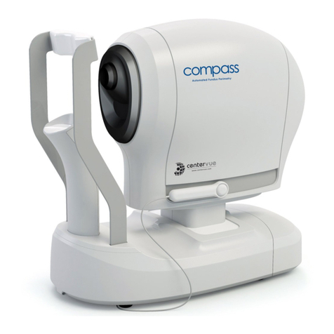
CenterVue
CenterVue COMPASS Disinfecting Instructions
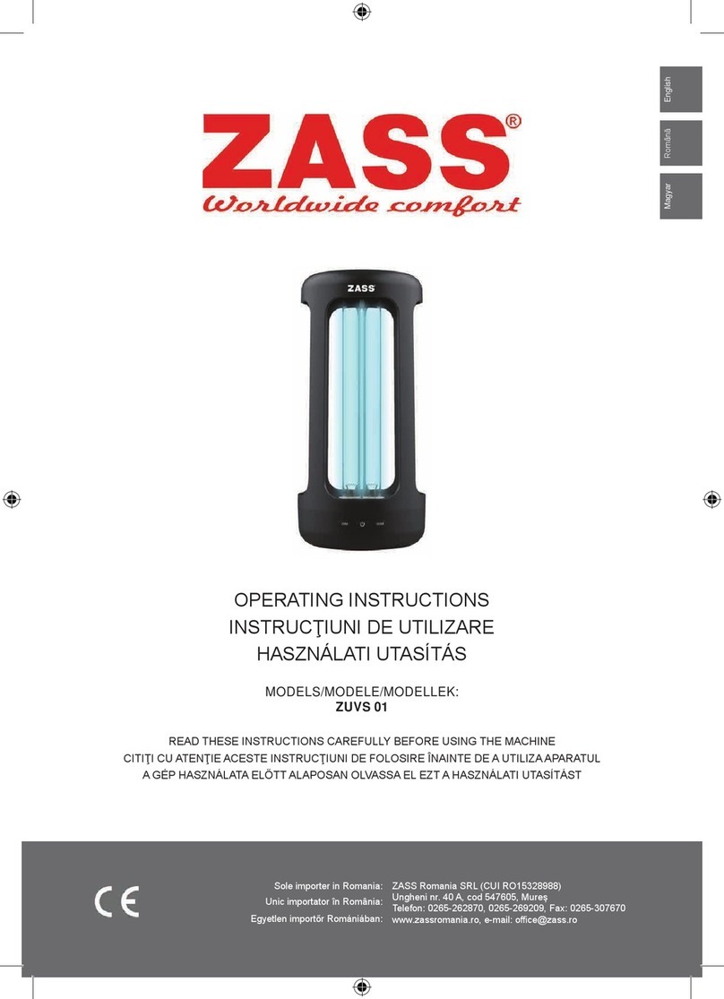
Zass
Zass ZUVS 01 operating instructions
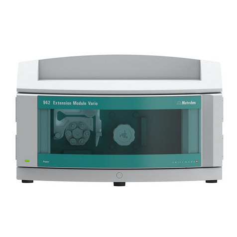
Metrohm
Metrohm 942 Extension Module Vario ChS-PP manual
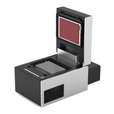
Opentrons
Opentrons Thermocycler Module GEN2 instruction manual
BACTcontrol
BACTcontrol microLAN Software manual

Zeiss
Zeiss Lightsheet 7 Installation requirements
Fritsch
Fritsch ANALYSETTE 18 operating instructions

Thermo Scientific
Thermo Scientific Precision WB159915 manual
Qiagen
Qiagen Hybrid Capture System Multi-Specimen Tube Vortexer... user manual

Tomy
Tomy MX-307 Operator's manual
Primus
Primus PSS500 Quick reference instructions

ZIVE LAB
ZIVE LAB ZIVE SP2 Hardware manual
