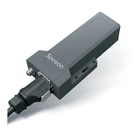
Spireon VehiclePath AT312 TT User manual

Local Fleet Management
VehiclePath.com
©2012 Spireon, Inc.
PRODUCT DESCRIPTION
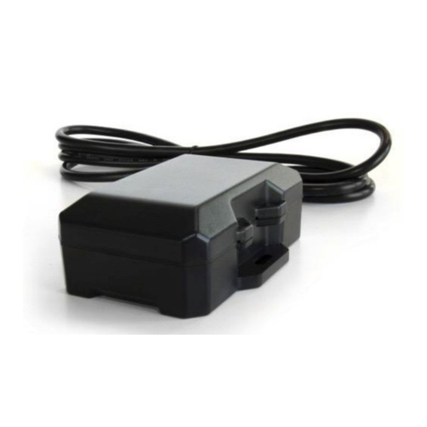
AT312 TT
Asset Tracking Device
The AT312 TT is part of the VehiclePath asset
tracking line, which has the ability to track in real
time.
This unit has been specically designed and
engineered to update on a daily basis (if not
connected to power) or on a 30-minute continuous-
tracking plan (if connected to power). When the unit
is connected to power, it will send an Auto Locate
every 24 hours.
If the unit is not connected to power, then it will
work off the internal battery and give an Auto
Locate every 8 hours. The device will automatically
generate Unauthorized Movement Alerts once it has
traveled 3 miles or more. It will continue to provide
an alert every 30 minutes until stationary.
The AT312 TT is built to withstand harsh environ-
ments and can function in up to 39 inches (1 meter)
of water. Its cellular and GPS antennas are
completely integrated. It also has an internal motion
sensor and internal battery.
TARGET MARKETS:
Trucking companies – local, long haul or intermodal
PRODUCT DIFFERENTIATORS:
Continuous tracking device
Internal battery back-up
Low monthly rate
OVERVIEW:
Low power consumption
(1mA in sleep mode)
Voltage monitoring and
low-battery notication
Over-the-air rmware
upgrade capability
Unauthorized Movement Alert
Power disconnect and
reconnect events
GSM Quad-band
(800/900/1800/1900 MHz)

Local Fleet Management
VehiclePath.com
©2012 Spireon, Inc.
PRODUCT SPECIFICATIONS
AT312 TT
Asset Tracking Device
PHYSICAL SPECIFICATIONS
Size: 4.87”L x 3.5”W x 1.25”H
Weight: 5.6 oz. / 158.76 grams
ENVIRONMENTAL SPECIFICATIONS
Temperature
Operating: -30° to 60° C / -22° to 140° F
Storage: -40° to 75° C / -40° to 167° F
WIRELESS SPECIFICATIONS
Wireless: GSM Quad band (850/900/1800/1900 MHz)
Regulatory Approvals: FCC / IC, PTCRB
GENERAL SPECIFICATIONS
Input Voltage: +8 to +30 VDC
Power consumption: tN"!WJOTMFFQNPEF
tN"!WXIFOSVOOJOHPSXIFOWJCSBUJPOJTTFOTFE
tN"!WXIFOUSBOTGFSSJOHBOESFDFJWJOHEBUBCVSTU
Antenna Connections
Cellular: Internal
GPS: Internal
LEDs
Orange Solid Communication established with cellular network
Orange Flash Looking for cellular network
Green Solid Good GPS signal
Green Flash Looking for GPS satellites
Red Solid Connected to continuous power source

Standard Installation
GPS Fleet Tracking
INSTALLATION GUIDE
Getting Started
Kit Contents:
UÊ /À>V}Ê`iÛViÊÜÌÊÌiÀ>Ê>Ìi>ÊEÊ>ÌÌ>Vi`ÊÜÀ}Ê>ÀiÃî
Wiring Diagram:
^Óä£ÓÊ-«Ài]ÊV°ÊÊÊÊÊÊÊÊÓä£Ó6*£ääÎ
Tools Required for
Installation:
UÊ *ÀÌ>LiÊ£ÓÊ6Ê«ÜiÀÊÃÕ««Þ
UÊ 6ÌiÌiÀÊÀÊÌiÃÌÊ}Ì
UÊ ÇÜ>ÞÊ«}Ì>Ê>`>«ÌiÀ
UÊ À`iÃÃÊ«ÜiÀÊ`À
UÊ £ÉnVÊ`ÀÊLÌ
UÊ 7ÀiÊÃÌÀ««iÀÉVÕÌÌiÀÉVÀ«iÀ
UÊ /ÕLiÊÃViÊV>Õ
UÊ £ÉnVÊ}ÀiÌ
UÊ iiVÌÀVÊ}Ài>Ãi
UÊ ,ÊiiVÌÀV>ÊÌ>«i
UÊ ,}ÊÌiÀ>Êi`Ã
UÊ È®Ê£äÊÝÊÏÊ/iÃÊiÝÊÜ>ÃiÀi>`Ê`ÀÊÊ
Ê «ÌÊÃivÌ>««}ÃVÀiÜÃ
UÊ £äÉÎÓÊÕÌÃ
UÊ >LiÊV>«ÃÊ
Biased Low:Ê«ÕÌÊÃÊ«Õi`ÊÌÊ}ÀÕ`Ê
LÞÊ`iv>ÕÌÊ>`ÊÜÊÃiÃiÊÜiÊÛÌ>}iÊÃÊ
>««i`ÊÌḚ̂Ê
Biased High:Ê«ÕÌÊÃÊ«Õi`ÊÌÊ>ÊÛÌ>}iÊ
LÞÊ`iv>ÕÌÊ>`ÊÜÊÃiÃiÊÜiÊÌÊÃÊV
iVÌi`ÊÌÊ}ÀÕ`°
Ê
WIRING DESCRIPTION:
,ÊÊ £ÓÉÓ{Ê6ÊÃÌ>ÌÊ*ÜiÀ
Ê >ÃÃÃÊÀÕ`
7/Ê ÌÊ1Ãi`
1Ê «ÕÌÊ£ÊÊL>Ãi`Ê}®
9"7Ê ÌÊ1Ãi`
,"7 Ê ÌÊ1Ãi`
, Ê ÌÊ1Ãi`
", Ê ÌÊ1Ãi`
S
TALLATI
O
N
GU
I
DE
etting Started

Standard Installation
GPS Fleet Tracking
Mounting the Device:
Preferred device placement is on forward-facing bulkhead near 7-way
receptacle with wires pointed downward.
UÊ ÃÌÊi>VÊ`iÛViÊÃiÀ>ÊÕLiÀÊ>`ÊVÀÀië`}ÊÌÀ>iÀÊÊÊÊ
number for the customer.
UÊ /iÊÃiÀ>ÊÕLiÀÊÜÊLiÊVÛiÀi`Ê>vÌiÀÊÃÌ>>ÌÊÃÊLiÊÃÕÀiÊ
to write it down before placing device.
UÊ V>ÌiÊÇÜ>ÞÊÀiVi«Ì>Vi°
UÊ >ÞâiÊÌÀ>iÀÊÌÊ`iÌiÀiÊLiÃÌÊ«>ViÊÌÊÕÌÊ`iÛVi°
UÊ iÛViÊÕÃÌÊLiÊÜÌÊ>«iÊÀi>VÊvÊÇÜ>ÞÊÀiVi«Ì>Vi°
Place device on designated spot and secure with four #10 x 3/4 Teks
hex self-tapping screws
Various locations for the 7-way receptacle, photos left and center. Photo on right is an example of proper
device placement.
Running the Wiring Harness:
This device requires a constant 12 or 24 VDC power source and an
asset ground connection.
UÊ ,iÛiÊLÌÃÊÌ>ÌÊÃiVÕÀiÊVÛiÀÊÌÊÇÜ>ÞÊÀiVi«Ì>Vi°
UÊ iÌÞ «ÕÊÇÜ>ÞÊÀiVi«Ì>ViÊÕÃ}ÊVÛiÀÊÌÊiÝ«ÃiÊÃ`iÊÊ
of receptacle.
UÊ /iÀiÊ>ÀiÊÎÊ`vviÀiÌÊÀÕÌ}Ê«ÌÃÊvÀÊÌiÊ*-ÊÜÀ}Ê
harness. Select best option for your application from below:
– Run to inside of 7-way receptacle as shown in photo, OR . . .
– Drill a hole in housing case of 7-way receptacle and run as
shown in middle photo on right OR
– Drill a hole in trailer close to 7-way, then run to back of
7-way receptacle case, photo right.
UÊ -iiVÌÊÞÕÀÊ«ÌÊ>`ÊÀÕÌiÊÜÀ}Ê>ÀiÃð
UÊ vÊ`À}ÊÃÊÀiµÕÀi`]ÊwÌÊiÊÜÌÊ£Én»Ê}ÀḭÊ
UÊ ««ÞÊÃViÊÃi>>ÌÊ>ÀÕ`Ê}Àḭ
UÊ ÃÌ>ÊV>LiÊV>«ÃÊÌÊÃÕÀiÊ>ÊÜÀ}ÊÃÊÃiVÕÀi`ÊÌÊÌÀ>iÀ°
UÊ iVÊi}ÌÊvÊÜÀiÃÊÊ*-ÊÜÀ}Ê>ÀiÃÃÊ>`ÊÌÀÊiÝViÃðÊÊ
Do not coil excess in receptacle housing.
UÊ V>ÌiÊ,Ê>`ÊÊÜÀiÃ]Ê«ÕÊÌÊÌiÊÃ`iÊ>`Êv`ÊÀi>}ÊÊ
excess wires over outside of wiring harness.
UÊ 7À>«ÊÀi>}ÊiÝViÃÃÊÜÀiÊÜÌÊiiVÌÀV>ÊÌ>«iÊÃÊ>Êi`ÃÊ>ÀiÊ
securely covered.
^Óä£ÓÊ-«Ài]ÊV°ÊÊÊÊÊÊÊÊÓä£Ó6*£ääÎ
BEWARE! Handle 7-way with
care to keep wire connections intact
– trailer wiring harness & components
are typically attached to cover.
BEWARE! All wires should
be flush with the trailer surface. Pay
particular attention to recessed areas
– to protect wires from hazards that
could catch or pull on them, run wire
flat against trailer into recesses.

Standard Installation
GPS Fleet Tracking
Locate Your Power Source:
Device requires constant 12 or 24 VDC power source to operate and
recharge internal battery. Ground wire must be attached to an asset
ground.
UÊ V>ÌiÊ18É-ÊÌiÀ>Ê>`ÊViÌiÀÊ«ÊÌiÀ>ÊÃ`iÊÌiÊÊ
Ê ÇÜ>ÞÊÌÀ>iÀÊ«Õ}°ÊÊ/iÊ18É-ʳ®ÊÃÕ`ÊLiÊÌiÊÌ«ÊÌiÀ>°ÊÊÊ
Ê /iÊViÌiÀÊ«ÊÌiÀ>ÊÜÊLiÊÊÌiÊ``iÊ®
ÊÊÊÊ Ìi\Ê/iÊ18É-ÊiÊÃÊÌiÊ«ÀiviÀÀi`Ê«ÜiÀÊÃÕÀVi°ÊvÊÊ
ÊÊÊÊÕÃÕÀiÊ>LÕÌÊVÃÌ>ÌÊ«ÜiÀÊÀÊ18É-ÊiÃÊV>½ÌÊLiÊ
located, use a digital voltmeter to locate an alternate power
terminal.
Connecting to POWER and GROUND:
UÊ *"7,\ÊÊ-iVÕÀiÊ,ÊÜÀiÊvÀÊÜÀ}Ê>ÀiÃÃÊÌÊ18É-Ê
Ê ÌiÀ>ÊLÕiÊÜÀiÊvÊÇÜ>ÞÊÀÊÌiÀÊVÃÌ>ÌÊ«ÜiÀÊÃÕÀVi®Ê
using wire stripper/cutters and ring terminals.
UÊ ,"1 \ÊÊ-iVÕÀiÊÊÜÀiÊvÀÊÜÀ}Ê>ÀiÃÃÊÌÊÜÌiÊÜÀiÊ
in 7-way receptacle using wire strippers/cutters and ring terminals
UÊ -iVÕÀiÊiiVÌÀV>ÊViVÌÃÊwÀÃÌ]ÊÌiÊ>««ÞÊ`iiVÌÀVÊ}Ài>ÃiÊÌÊ
both power and ground terminals to protect connections.
Confirm Connectivity:
UÊ wÀÊ>ÊëViÃÊ>`iÊvÀÊ«ÜiÀÊEÊ}ÀÕ`ÊViVÌÃÊ>ÀiÊÊ
Ê wÀÞÊ>ÌÌ>Vi`°
UÊ wÀÊ>ÊëViÃÊ>ÀiÊÜiÃÕ>Ìi`ÊvÀÊÌiÀÊViVÌÃÊÀÊÊ
potential shorts.
UÊ wÀÊ>ÊÃiÊÜÀ}Ê>`ÊÃ>VÊ>ÃÊLiiÊÀi`ÕVi`Ê>`ÊÃiVÕÀi`°
UÊ *>ViÊÌiÊÇÜ>ÞÊÀiVi«Ì>ViÊVÛiÀÊÊÌiÊÕÃ}°
UÊ Beware! Do not pinch wires during re-assembly.
Operation Verification:
UÊ iVÌÊ>ÊiÝÌiÀ>Ê£ÓÊ6Ê«ÜiÀÊÃÕÀViÊÌÊÌiÊÇÜ>ÞÊÀiVi«Ì>ViÊ
and power on. You must have 12V to wake each device from the
shipping hibernation mode.
UÊ Ê-"Ê,ÊÊÊÌiÊ*-Ê`iÛViÊÃÕ`ÊÕ>Ìi°ÊÊ
UÊ 7iÊ`iÛViÊÃÊ«ÜiÀi`]ÊÌiÊ9"7Ê*-®Ê>`Ê,ÊVi®ÊÊ
LEDs will flash on and off while searching for signals. When full
Ê Ã}>ÊÃÌÀi}ÌÊÃÊ>ViÛi`Ê}iiÀ>ÞÊÓÊxÊÕÌiî]ÊLÌÊÃÊÜÊ
continuously illuminate.
UÊ }ÊÌÊÌiÊÜiLL>Ãi`ÊVÌÀÊ«>iÊÌÊÛiÀvÞÊÌiÊÃÌ>>ÌÊÊ
Ê >vÌiÀÊÌiÊ9"7Ê>`Ê,ÊÃÊ>ÀiÊÃ`ÞḚ̂
GPS and Cell Signal Basic Information:
UÊ *-ÊÃ}>ÊÃÌÀi}ÌÊÃÊi>ÃÕÀi`ÊLÞÊÌiÊÕLiÀÊvÊÃ>ÌiÌiÃÊ
detected by the device. A minimum of six satellites should be
reporting when the vehicle is in the open with fewer satellites
reporting when tested in or near buildings.
UÊ iÕ>ÀÊÃ}>ÊÃÌÀi}ÌÊÃÊÀi«ÀÌi`Ê>ÃÊ,--Ê,iViÛi`Ê-}>Ê
Ê -ÌÀi}ÌÊ`V>Ì®°ÊVVi«Ì>LiÊ,--ÊÀi>`}ÃÊ>ÀiÊ>ÞÊÛ>ÕiÊÊ
Ê }Ài>ÌiÀÊÌ>Ê££ä`°
^Óä£ÓÊ-«Ài]ÊV°ÊÊÊÊÊÊÊÊÓä£Ó6*£ääÎ
Table of contents
Other Spireon GPS manuals

Spireon
Spireon FL4 User manual

Spireon
Spireon SkyLink Talon User manual

Spireon
Spireon FleetLocate FL12 User manual

Spireon
Spireon GoldStar ATS300 User manual

Spireon
Spireon JKS3 User manual

Spireon
Spireon Flex2PL User manual

Spireon
Spireon FL18 User manual

Spireon
Spireon FL4 User manual

Spireon
Spireon JG-LS User manual

Spireon
Spireon GoldStar ATS200 User manual