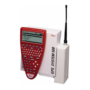
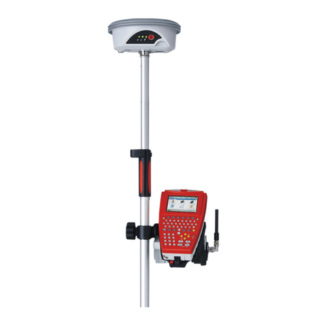
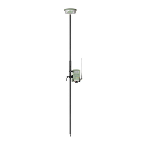
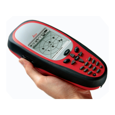
Leica GPS500 User manual

Version 2.0
English
50403020
Getting Started with Static and Kinematic Surveys
GPS System 500

2Static and Kinematic Surveys-2.0.0en
Congratulations on your purchase of a new Leica
System GPS500.
System GPS500

3
Static and Kinematic Surveys-2.0.0en
Introduction
Equipment checklist for static and rapid static measurements using system 500
Setting up System 500 for a static survey
Using the TR500 terminal
Taking Static / Rapid-Static measurements
Exploring the sensor status during operation
Changing the system configuration parameters
Creating new configuration sets
Programming wake-up sessions
Kinematic and Stop & Go surveying - using static initialization
Kinematic "on the fly"
Practical hints for kinematic, Stop & Go and
Miscellaneous
Appendix: Summary of status icons
Appendix: Measuring antenna heigths
View of chapters
View of chapters
6
7
8
9
13
23
29
33
34
37
43
45
46
47
49

4Static and Kinematic Surveys-2.0.0en
Contents
Contents
Introduction ................................................... 6
Equipment checklist for Static and Rapid-
Static measurements using System 500 ..... 7
Setting up System 500 for a static survey ... 8
Using the TR500 terminal ............................. 9
Menus ......................................................................... 9
Entering information ....................................................10
Listboxes .................................................................... 11
Hardkeys ....................................................................12
Taking Static / Rapid-Static measurements13
Step 1: Power on ........................................................13
Step 2: Study the icons ...............................................13
Step 3 (optional): Format your memory card .................15
Step 4: Begin a survey ................................................16
Step 5: Logging raw data .............................................19
Step 6: Ending a survey ..............................................21
Suggested exercise: Measure a very short baseline .....22
Exploring the sensor status during operation
...................................................................... 23
Satellite status............................................................24
Stop & Go indicator .....................................................25
Battery and memory status .........................................26
Display current navigated position ................................27
Suggested exercise: Get familiar with system status ....28
Changing the system configuration
parameters ................................................... 29
Turning on the illumination of the terminal .....................30
Changing the observation rate ......................................30
Setting local time zone................................................31
Changing distance units from meter to feet ...................32
Creating new configuration sets ................ 33
Programming Wake-up Sessions .............. 34

5
Static and Kinematic Surveys-2.0.0en
Contents, contd.
Contents
Kinematic and Stop & Go surveying - using
static initialization ........................................ 37
Introduction and general comments .............................37
Equipment setup for Kinematic and Stop & Go surveys 38
Carrying out Kinematic and Stop & Go measurements .39
Initialization on a known point ......................................42
Kinematic "on the fly" ................................. 43
Practical hints for Kinematic, Stop & Go and
Kinematic on the fly measurements .......... 45
Miscellaneous .............................................. 46
Appendix: Summary of status icons ......... 47
Appendix: Measuring antenna heights ..... 49

6Static and Kinematic Surveys-2.0.0en
Introduction
The purpose of this short manual is
to give guidelines and useful hints on
how to perform static, rapid static and
kinematic surveys using SR510,
SR520 or SR530 GPS receivers
without utilizing Realtime techniques.
Realtime applications, based on the
use of radio modems - in particular
RTK (Real-Time-Kinematic) opera-
tion with SR530 receivers - are
described in the booklet "Getting
Started with Real-Time Surveys".
Full description of all features and
functions of System 500 can be
found in the "Technical Reference"
Manual which is available as an
electronic PDF document only. This
manual can be found on the SKI-Pro
installation CD. For more information
please refer to the file
\MANUALS\README.TXT on the
SKI-Pro installation CD.
It is assumed that the reader of this
manual is familiar with the principles
of GPS Surveying, i.e. he knows the
concept of differential measure-
ments, the need for a reference
receiver, etc. A basic introduction of
these principles is given in the
booklet "General Guide to Static and
Rapid Static".
After studying these guidelines a user
will know the basic concepts and
principles of how to operate System
500 and carry out static, rapid static
and kinematic GPS surveys.
Introduction
6

7
Static and Kinematic Surveys-2.0.0en
Equipment checklist for Static and Rapid-Static measurements using System 500
Batteries are needed to power the
sensor. Standard are two camcorder
batteries which are plugged into the
backside of the sensor and power the
unit for about 6 hours.
Warning
Brand new camcorder
batteries need about 5
charging cycles before
reaching the full capacity. It is
highly recommended to fully
charge and decharge
camcorder batteries for 4 to 5
times before start-ing using
them for practical fieldwork.
This is easily accomplished
by plugging them into the
sensor and having the sensor
turned on until the sensor
switches off automatically
once the batteries get flat.
Then simply recharge them
and repeat this exercise.
Equipment checklist
If you want to use System 500 for
Static or Rapid-Static survey then the
minimum equipment you need is a
pair of System 500 units.
Each unit comprises a SR510 or
SR520 or SR530 sensor.
A single frequency SR510 sensor
requires an AT501 single frequency
antenna; SR520 and SR530 sensors
need to be connected to a dual-
frequency antenna, normally the
AT502 standard antenna or - for
utmost accuracy - high precision
chokering antennas: either a AT503
or AT504.
An antenna cable is needed to
connect the sensor and the antenna.
A TR500 terminal - a keyboard &
display device - is needed to easily
start the operation, check system
status and manipulate sensor
parameters.
6
7

8Static and Kinematic Surveys-2.0.0en
Setting up System 500 for a Static survey
Setting up System 500 for a static survey
Connect the antenna to the sensor
using the antenna cable.
Plug two camcorder batteries into the
backside of the sensor. Alternatively
or in addition you might want to
power the sensor externally. In this
case connect a GEB71 battery to one
of the PWR- ports of the sensor.
Attach the TR500 terminal to the
sensor, either directly or via a
connection cable by plugging it into
the TERMINAL-port on the sensor.
Insert a PC-card into the sensor.
Warning
Lock the lid carefully after
insertion of the card in order
to prevent water and dust
from getting inside the
sensor.
Use the hook on the backside of the
sensor to hang it on one of the tri-pod
legs. Alternatively you may want to
leave the sensor inside the shipping
case.
Your System 500 sensor is now fully
ready for operation.
Successful GPS surveys require
undisturbed satellite signal reception.
This means that GPS sensors should
be set up in locations which are free
of obstructions. No obstacles like
trees, buildings, mountains, etc.
should block the line between the
GPS antenna and GPS satellites.
This holds true in particular for the
sensor which serves as the
reference.
For static and rapid static surveys,
the antenna must be kept perfectly
steady throughout the whole
occupation of a point. This means
that the AT501 or AT502 antenna will
usually be put on a tripod.
Center and level the tripod precisely
above the survey marker. Place and
lock the carrier in the tribrach. Mount
the antenna onto the carrier.
6
7
8

9
Static and Kinematic Surveys-2.0.0en Using the TR500 terminal
Using the TR500 terminal Menus
A typical example can be found in
the main menu:
You can see 7 different choices. Line
"1 Survey" is highlighted which
means that this is the currently
selected choice.
You can navigate up and down the
screen using the cursor up / down
keys on the terminal. The highlighted
bar will follow accordingly. For
instance press the "cursor down key"
twice to highlight "3 Applications":
The function keys at the bottom of the
screen describe certain commands. If
for instance you want to enter the
"Applications" part of the software you
press F1 CONT (to continue).
In order to operate System 500 some
interactions between the user and the
TR500 terminal are usually required.
You will find the operating concept of
the onboard software intuitive and
easy to use. All screens and panels
are steered in the same way which
makes the software very userfriendly
and easy to learn.
This chapter explains by use of some
examples how to operate the
terminal. These operational
guidelines apply to all parts of the
System 500 onboard software.
We basically distinguish between
menus and screens which require a
certain input.
6
7
8
9

10 Static and Kinematic Surveys-2.0.0en
Using the TR500 terminal
Menus, continued Entering information
A typical example can be found in
the main Survey panel:
Two inputs have to be made here, the
Point Id and the Antenna Height. Use
the cursor down / up keys to move to
the desired input field. In the current
example the Point Id can be entered.
Use the alphanumeric keys on the
terminal to enter the information.
Use the CE key to correct any typing
error.
Use the ENTER key to conclude the
input.
A shortcut is to press the numbers
which are associated with each
choice directly. For instance if you
press "6" you will get straight into
"Configure"
6
7
8
9

11
Static and Kinematic Surveys-2.0.0en Using the TR500 terminal
ListboxesEntering information, contd.
Use numeric keys to enter the
antenna height.
When ENTER is pressed the focus is
moved to the next input field:
The input for Configuration Set, Job
and Antenna has to be made based
on a list.
Press ENTER to open the highlighted
listbox. A list pops up from which a
choice has to be made:
Use the cursor down / up keys to
move the selection bar down or up the
list. Select your input by highlighting
the particular line.
6
7
8

9
Some input fields expect a predefined
input. The choices are available in a
list which is kept behind the input
field.
Input fields based on a listbox are
identified by a small triangle which
appear on the right side of the field.
The following example shows 3 such
input fields in one screen:

12 Static and Kinematic Surveys-2.0.0en
Using the TR500 terminal
Listboxes, continued
Press F1 CONT to confirm the
selection. This will then also close
the listbox
You can speed up the selection by
entering the name of your choice. If
in this particular example "T" is
entered, the focus will automatically
move to "TEST_PP Rapid Static
PP".
On the right side of the screen you
see a vertical "scroll bar" which indi-
cates the current positio n within the
list. In this particular example the
current focus is about 20 % below
the top of the list. Such a scrollbar
becomes useful when the listbox is
very long.
If the listbox is very long it might
become cumbersome to navigate by
pressing cursor down / up to move
down and up the list. In such cases
press the SHIFT key to get access to
page down / up, home and end keys:
Another way to make a selection
from a listbox is by using the cursor
left / cursor right keys. Instead of
opening a list box press the cursor
left or cursor right keys to toggle
between different choices.
The terminal supports some
additional useful hardkeys:
The ESC key allows you to "escape"
from a screen. Instead of executing a
command you get back to the
previous screen.
The STATUS key provides direct
access to all system status informa-
tion, based on a certain menu
structure
The CONFIG key allows to change
configuration parameters during
operation.
6
7
8
9
Hardkeys

13
Static and Kinematic Surveys-2.0.0en Taking Static / Rapid-Static measurements
6
7
8
9
13
Taking Static / Rapid-Static measurements
Step 2: Study the icons
Upon power on you will first recognize
the "Number of visible Satellites"
icon, indicating the number of
satellites which are theoretically
visible at the current location and
time. Usually this number varies
between 4 and 10, depending on the
satellite geometry.
Next to this symbol you find the
"Number of Satellites used on L1 /
L2" icon, indicating the number of
satellites currently tracked either on
L1 or on L2.
Upon power on you will read L1: 0,
L2: 0. It will take about 30 seconds
until these number will start changing
and very soon reach the number of
visible satellites.
Both "Number of visible satellites"
and "Number of satellites used" icons
will change from time to time, re-
flecting changes in the satellite
geometry due to either the rise of
new satellites or the setting of de-
scending satellites.
Step 1: Power on
Accuracy Status
Position Mode
No. visible Satellites
No. Satellites used on
L1/L2
Radio Status
GSM Status
Memory Status
Auto Position Log. Status
Observation Log. Status
Local Time
Battery Status
Turn on the sensor by pressing the
ON-button on the terminal. One of
the following two screens will appear
on the display:
Most important at this stage is the top
part of the screen which contains
several symbols (icons) which
indicate the current system status.

14 Static and Kinematic Surveys-2.0.0en
Taking Static / Rapid-Static measurements
6
7
8

9
3
Step 2: Study the icons, continued
If the "number of satellites used"
differs from the "number of visible
satellites" make sure you place the
antenna in an open area without
obstructions, since any obstacle will
block the view of satellites.
When you switch on the unit for the
very first time it might take a maxi-
mum of 5 minutes until all satellites
are tracked. This can happen in case
your current location differs
significantly (i.e. > 1000 km) from the
initial position which is the position
where your sensor has been used
before. Once you are tracking
satellites, the position memory in the
sensor will be updated.
The battery status icon at the right
side of the icon line shows from
which source the sensor is currently
powered. A and B indicate the
internal batteries, E an external
battery source. The symbol also
indicates the voltage level of the
currently used battery in 4 different
stages from "full" (fully black) to 2/3
to 1/3 and "almost flat" (white color).
The memory status icon gives
several information: whether memory
for logging data is available or not.
Options are either a PC-card or
internal memory. If a PC card is
available and configured for use then
at this stage an arrow indicates the
fact that it is safe to remove the PC-
card from the sensor. The little bar on
the right side indicates the available
memory on either the PC-card or the
internal memory.
Warning
You cannot proceed from
here if no memory device is
avail-able. Insert a PC-card
other-wise no GPS survey
can be carried out.
All status symbols which are relevant
for static and kinematic measure-
ments are listed in the appendix.
Once a minimum of 3 satellites is
tracked the sensor can start
computing a position. As soon as a
position is available it will be
indicated by an icon on the far left of
the status line. Since for post-
processing surveys no realtime link
will be used, the icon will always
indicate the availability of an
autonomous position ("navigated
position") with an accuracy of about
100 meters.
As soon as the position icon
becomes visible the sensor is in a
stage where practical operation can
commence.
If the position icon does not become
visible even after one or two minutes
then the sensor is still not tracking
satellites. If the "number of satellites
used" is still zero please check
whether the antenna cable is
connected properly to both sensor
and antenna.

15
Static and Kinematic Surveys-2.0.0en Taking Static / Rapid-Static measurements
6
7
8
9
13
Step 3 (optional): Format your memory card
You are now in the Utilities \ Format
Memory Module panel:
If you want to format the PC-card just
press F1 CONT to format the card. If
you want to format the internal
memory press ENTER. A listbox
opens which allows you to select the
internal memory.
Before you start logging data you
may want to (re-)format your PC-card
or your internal memory.
This step is only necessary if
a completely new PC-card is
used or all existing data
should be deleted !
Press 4on the terminal or use the
cursor down key to highlight the line
"4 Utilities", then press ENTER;
alternatively press F1 CONT.
(If only lines 1 to 3 are visible at this
stage press F4 SHOW first).
Then press 2to get access to the
"Format Memory Module" panel, or
alternatively use the cursor key to
navigate to "2 Format Memory Mod-
ule" and press ENTER; again
alternatively press F1 CONT.

16 Static and Kinematic Surveys-2.0.0en
Taking Static / Rapid-Static measurements
6
7
8
9
3
Step 3 (optional): Format your memory card, continued
Once the formatting of the card is
completed the MAIN\ panel will
reappear.
Step 4: Begin a survey
Enter the Survey operation by either
pressing 1in the Main\ panel or by
first navigating to "1 Survey" via
cursor keys and then pressing
ENTER or F1 CONT.
The following panel will appear:
Some basic decisions have to be
made in this panel:
Which configuration set should be
activated, in which job the raw data
should be stored and which antenna
setup should be used.
Use the cursor key to highlight
Internal, then press ENTER. Then
press F1 CONT in order to start the
formatting process of the internal
memory.
Warning
By activating the format
command all data will be lost!
Make sure that all important
data which resides on the
PC-card is properly backed-
up before reformatting the
card. If you want to reformat
the internal memory make
sure that all important data is
first transferred to the PC.
If you realize that you do not want to
format the memory device, simply
press ESC instead of F1 CONT. This
keystroke brings you always a step
back into the previous panel without
execution of any command.

17
Static and Kinematic Surveys-2.0.0en Taking Static / Rapid-Static measurements
6
7
8
9
13
Step 4: Begin a survey, continued
Now use the cursor up or cursor
down key on the terminal to highlight
the PP_STAT line. Then press
ENTER or F1 CONT.
Jobs are used to organize and
structure the data you collect in the
field. Jobs can comprise an unlimited
number of points together with all
related information (raw measure-
ments, codes, point annotation, etc.).
It is suggested to create a new job
whenever you start a new project.
Upon formatting the memory device
(i.e. PC-card or internal memory) a
default job is automatically created.
You can either use this job straight
away or you can create your own job
by doing the following:
Move the cursor up or cursor down
key of the terminal into the input field
for jobs. Then press ENTER. The
following lisbox will appear:
Then a list box showing all available
sets becomes available:
A Configuration Set (Config Set) is a
collection of certain sensor
parameters needed to perform a
certain operation, like data recording
rates, point id templates, data
formats, antenna types, coding
methods, etc.
Several default configuration sets
exist which cover standard survey
scenarios. How to create new
configuration sets is described in a
later chapter as well as in the
Technical Reference Manual.
For static survey you should select
the PP_STAT configuration set. You
can make this selection either by
using the cursor left key to toggle
between all available configuration
sets until PP_STAT appears or you
can highlight the input field and press
ENTER.

18 Static and Kinematic Surveys-2.0.0en
Taking Static / Rapid-Static measurements
6
7
8
9
3
As an example we can create a new
job called "Test":
After pressing F1 CONT the list of
available jobs is updated and now
also shows the job "Test":
You can now enter a name for a new
job; press ENTER upon completing
the input of the name. Input fields for
description and creator are optional
and can be left blank.
By default the new job will be
assigned to the PC-card. If needed
this can be changed to internal by
toggling this input field to "Internal".
Pressing F1 CONT which confirms
the creation of a new job name and
its location. Press ESC if you want to
leave this field without creating a new
job. Pressing F6 QUIT has the same
effect.
Now press F1 CONT to confirm the
selection of the newly created job.
Finally you have to select the
antenna type and antenna setup
which you are using. Normally this
will be AT502 on tripod (or AT501 on
tripod in case of a SR510 sensor).
See Technical Reference Manual
"Measuring Antenna Heights" for
further details.
Step 4: Begin a survey, continued
Now press F2 NEW. The following
panel appears:

19
Static and Kinematic Surveys-2.0.0en Taking Static / Rapid-Static measurements
6
7
8
9
13
Step 4: Begin a survey, contd. Step 5: Logging raw data
As soon as you are tracking a
minimum of 4 satellites, the position
icon is visible and the antenna is
placed correctly above the survey
marker, you should press F1 OCUPY.
This activates logging of raw data
and the screen changes accordingly:
The position mode icon has changed
to static, indicated by a symbol of a
tripod.
Pressing F1 CONT finishes this
startup sequence.
It is time to check again the icons on
the top of the display: The position
icon should be available, the position
mode icon still indicates "moving" ,
the "number of satellites visible" icon
should display a number greater or at
least 4, and the number of used
satellites should be identical to the
number of visible satellites.
This selection is made in the usual
way: first use the cursor down key to
get this input field highlighted. Then
use the cursor left key to toggle
among the several options until the
right one appears. Alternatively you
can press the ENTER key to get a
listbox from which the choice can be
made.
Now all required settings for a static
survey are made. The Survey \ Begin
panel looks as follows:
We are now within the main Survey
panel. The way the sensor is
currently configured, the panel will
look as follows:

20 Static and Kinematic Surveys-2.0.0en
Taking Static / Rapid-Static measurements
6
7
8
9
3
Step 5: Logging raw data, continued
Enter this reading into the antenna
height field. Since the antenna you
have selected is "AT502 Tripod"
(AT501 Tripod in case of a SR510
sensor) the offset from the height
hook to the phase center of the
anten-na is automatically taken care
of.
These are the only two inputs needed
for surveying a point.
The Static observation counter
(Static obs) will now go up every 10
sec-onds (because this is the default
logging interval).
The displayed GDOP value indicates
the current satellite geometry; the
lower the value the better.
Warning
The antenna must not be
moved while data is logged,
other-wise the quality of post-
processed coordinates will be
impaired !
Warning
The PC-card must not be
removed while in the Survey
panel. If the card is taken out
of the sensor all stored data
might get corrupted,
preventing SKI-Pro from
successfully reading the data
on the card.
The TR500 terminal may now be
disconnected. This will have no effect
on the survey ! Datalogging will
continue. When reconnecting the ter-
minal the same panel will reappear.
Datalogging should continue
depending on your observation plan:
a sensor used as reference has to
run permanently until all rover site
occupa-tions are completed. If a unit
is operated as a roving receiver the
site occupation time depends mainly
on the baseline length and your
accuracy requirements. See "General
Guide to Static and Rapid Static" for
details.
Raw data (containing pseudorange
and phase measurements to each
tracked satellite) is logged at
predefined intervals (by default every
10 seconds, which is the
"observation recording rate" set in the
default PP_STAT configuration set):
Enter a Point Id by filling in the input
field. If you make a typing error
correct the mistake by pressing the
CE key (Clear Entry). Complete the
input by pressing ENTER.
Now use the height hook to
determine the height of the antenna
above the survey marker. Insert the
height hook into the carrier and
measure the height between the
white mark at the bottom of the
height hook and the survey marker.
A new icon is now displayed which
indicates that raw data is logged.
Other Leica GPS manuals

Leica
Leica MojoMINI User manual

Leica
Leica apMK12 User manual

Leica
Leica MX400 User manual

Leica
Leica INEX 1-1296 User manual

Leica
Leica T-Scan5 User manual

Leica
Leica GPS System 500 User manual

Leica
Leica mojo3D User manual

Leica
Leica GG02 User manual

Leica
Leica DistoX2 User manual

Leica
Leica GPS1200 Series Product manual

Leica
Leica MK8 User manual

Leica
Leica mojo3D User manual

Leica
Leica iNEX User manual

Leica
Leica GPS1200+ Product manual

Leica
Leica MojoMINI User manual

Leica
Leica SR20 User manual

Leica
Leica mojo 3D User manual

Leica
Leica GPS1200 Series User manual

Leica
Leica Digilux 2 User manual

Leica
Leica GS09 User manual