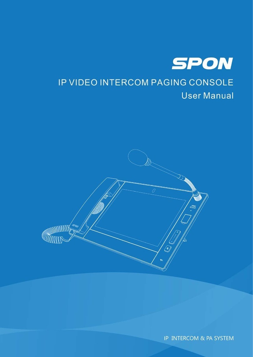
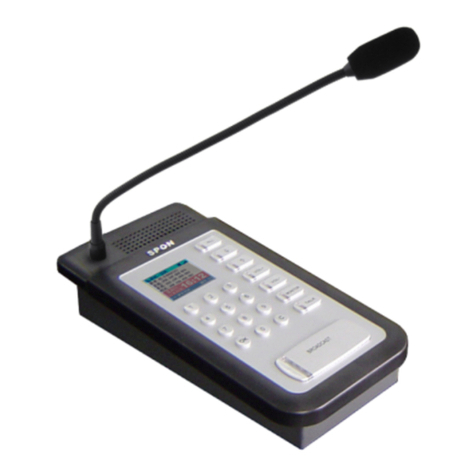
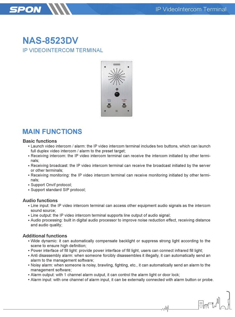
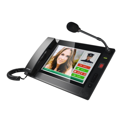
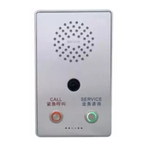
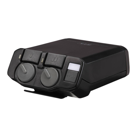
Spon NAS-8523CV User manual


Contents
Summary...........................................................................................................................................................................................................1
Safety precaution..........................................................................................................................................................................................1
Products introduction....................................................................................................................................................................................2
Hardware interface description ...................................................................................................................................................................3
Introduction......................................................................................................................................................................................................4
Packing list.....................................................................................................................................................................................................4
Wiring..............................................................................................................................................................................................................5
Basic network settings..................................................................................................................................................................................5
User-defined terminal parameters..............................................................................................................................................................6
Log-in web page............................................................................................................................................................................................6
Network parameters .....................................................................................................................................................................................7
Server parameters........................................................................................................................................................................................7
SIP parameters..............................................................................................................................................................................................8
Audio parameters..........................................................................................................................................................................................9
Talk parameters...........................................................................................................................................................................................10
Alarm parameters........................................................................................................................................................................................ 11
Password setting.........................................................................................................................................................................................12
Language Setting........................................................................................................................................................................................13
Update Firmware (Note: Otherwise special needs, please do not update the firmware )................................................................13
Reset to Defaults.........................................................................................................................................................................................13
Reboot device..............................................................................................................................................................................................14
System Log..................................................................................................................................................................................................14
Other functions............................................................................................................................................................................................15
Basic Function...............................................................................................................................................................................................15
Initiate the Intercom....................................................................................................................................................................................15
Receiving Broadcasting .............................................................................................................................................................................15
Trouble Removal...........................................................................................................................................................................................16
Copyright statement.....................................................................................................................................................................................17
0

IP Video HD Intercom Terminal User Manual
Summary
Safety precaution
Please abide by the warning and the relevant safety tips.
Please take this manual in convenient place after you reading the guide for future reference.
Warning
The sign means there is potential safety hazard, when operate wrong may result in death or serious injury.
The sign is used to remind the user that attached is the important operation and maintenance data.
Setting and Installation
(1)Avoid being wet with the water.
Don’t make the machine or exposed to rain water or other liquid contamination of the environment, or lead to fire or get an
electric shock.
(2)Don’t use unspecified voltage.
Using the marked voltage on the machine.
Using more than the logo of voltage could lead to fire or shock.
(3)Don’t scratch the power cord.
Don’t scratch the power cord or cut it.
Simultaneous, keep the power line far way from heated objects, put heavy things on it will lead to fires or electric shock.
Using machine
(1)In case of the anomalies
Please turn off the power supply immediately when finding the abnormal phenomena, please connect with the agency. if you
continue to use, it will likely fires or shock.
·The smoke or odor of the machine.
·The inside of the machine is flooded by water or foreign bodies intrusion.
·Machine falling or machine shell damage.
·The power cord damage (wire core is exposed of broken, etc)
·Fault (eg :it can’t network, no sound ...ect)
(2)Don’t open the machine internal or modify the machine.
Do not let foreign matters invade the machines internal.
Don’t let the metal items or inflammable objects inserting machine such as foreign inserting machines or throw into the vents
machines internal, otherwise will likely cause fires or electric shock.
(3)Please do not touch it when thundering
To avoid electric shock, please do not touch the machine and the plug when lightning, etc.
(4)Please do not place containers with liquid or small metal objects on machine above.
If gets upset containers, and let the fluid inflow to the machine that will likely fires or cause shock.
(5)Do not open the machine internal or modify the machine.
The machine internal contains high voltage parts, once open the cover or modify the machine, it will likely fires or cause shock.
All the maintenance and other machine modification should be operated by professional personnel.
(6)Maintenance and the precautions for not using in a long time.
While maintenance, if the machine is not using for 10 days or more, please shut off power supply switch for safety. If do not
comply with this provision, it will likely cause electric shock or fires.
1

IP Video HD Intercom Terminal User Manual
Products introduction
IP video HD intercom terminal which is embedded with IP Audio digital audio technology of independent intellectual
property right, equipped with HD camera, power input interface, alarm input, line input, line(or recording) output port, combined
with other camera device, it can support two-way video intercom. IP HD video intercom terminal can support ONVIF protocol
and it can realize all day audio and video recording.
Features
Ultra-wide-angle camera, can show clear face, support multi-resolution video output;
Support ONVIF protocol, provide 1 line standard ONVIF video and audio interface, can realize all day sound and video
recording.
With microphone, can realize spot real condition monitor;
Can connect with three color door light, according the alarm signal to control the open of three color door light and
through the color of three color light to quickly recognize the alarm contents.
Terminal can connect external alarm control module to expand alarm input and output interface.
Can realize the auto-change between day-mode(color picture),night-mode(black and white picture)mode.
Wide dynamic: according the spot of poor light and strong light to auto-makeup or hold back to ensure HD degree.
Provide makeup light power interface, user can connect external infrared light
It will be accessed if the Ethernet is available.
Compatible with standard SIP protocol, realize intercom with other SIP terminals.
2

IP Video HD Intercom Terminal User Manual
Hardware interface description
【
Front
】
【
Back
】
【
Front
】
①Loudspeaker :amplify the remote sound.
②Photoresistor: test the ambient illumination, control camera day and night mode.
③Wide angle camera: collect local video.
④Alarm button: click this button to call the target terminal named by the server and trigger alarming, lighten the three color
door light or alarm light(it can’t connect the three color door light)
⑤Intercom button: click this button to call the target terminal named by server.
⑥Microphone: collect the local audio.
【
Back
】
①Procedure update port: insert the SD card to update the program;
②Power interface, function definition as following picture shows:
③Cascade port:connect with alarm control module, function definition as following picture shows
Note: 1 pcs of IP HD video intercom terminal can be connected with 2 pcs of alarm control modules and 1 pcs of three color
door light.
④Integrated interface, functions definition as following picture shows:
⑤Line input interface: collect external devices(such as pickup)audio signal as the audio input of intercom(or broadcast)
⑥Network input interface: insert the cable and connect the server.
3

IP Video HD Intercom Terminal User Manual
Introduction
Packing list
IP HD video intercom terminal includes follow parts, checking all the parts before install it ,if any parts are missing ,please
contact with your distributor
(1) IP HD video intercom terminal 1 pcs
(2) Wiring terminal (3.5-3P) 1 pcs
(3) Wiring terminal (3.5-4P) 1 pcs
(4) Wiring terminal (3.5-6P) 1 pcs
(5) Allen screw(M3*12)4 pcs
(6) Allen screwdriver 1 pcs(small size)
(7) Cable 1 pcs (with 2.54-2P wiring terminal )
4

IP Video HD Intercom Terminal User Manual
(8) Quick installation manual 1 pcs
(9)Certification 1pcs
Wiring
(1) Use one end of the power adapter to connect with the power port of IP video intercom terminal, the other end connect
with the power socket.
(2)Use one end of the Ethernet cables to connect with the IP video intercom terminal, the other end connect with the
switcher.
(3) Connect the alarm light, alarm control module, alarm remove button, fill light to corresponding interface.
Basic network settings
Connect the cable and power on as the installation manual, enter the web page of IP video intercom terminal, then revise
the terminal network parameters according to the live environment, after finish the setting, click “ok”. Please refer to the specific
operation from the network parameters setting of the user-defined parameters.
5

IP Video HD Intercom Terminal User Manual
User-defined terminal parameters
Log-in web page
(1) Please input the network intercom terminal IP address to the browser address column (the factory default IP address
is 192.168.1.101, it will automatically play the IP address when press the terminal key without the cable inserted), then
enter.
(2) Input the user name and password in the web page (the default user name and password is admin).
(3) Click OK to enter IP video intercom terminal web page.
6

IP Video HD Intercom Terminal User Manual
Network parameters
The parameters specification as following:
Terminal ID The only number to identify the terminal, it can’t repeat with other terminal or host,
the factory default is 1.
Local port Notes: otherwise the special condition of the port, please don’t modify randomly.(the
factory default is 2046)
Terminal IP Terminal IP address, the factory default is 192.168.1.101
Subnet mask The subnet mask of the terminal
Default gateway The network gateway of the terminal
Primary DNS
server The primary domain name interpreter IP of terminal.
Secondary DNS
server The secondary domain name interpreter IP of terminal.
Server parameters
The parameters specification as following:
Primary server The server address of terminal login.
Secondary server When the primary server unable to connect, it can login on the secondary server.
When the primary server is connected, restart and login to the preferred server.
7

IP Video HD Intercom Terminal User Manual
Version server
Version server IP, when the terminal restart it can connect to the version server to
update program automatic.
FTP server
File server IP, it can download the file contents named by server to the SD card or
built-in Flash through FTP .
FTP user name Login the file server user name
FTP password Login the file server password
Login interval Request login the server interval time
SIP parameters
The parameters specification as following:
SIP enabled or not
SIP function is enabled or
not: SIP function is enabled but the SIP calling is
forbidden, so the SIP phone can call to this device, but this device can`t call to SIP
phone, the device can call to the SIP phone when the SIP function and the calling
function are enabled, it can`t make
SIP conversation when the SIP function is
forbidden.
SIP server IP SIP server address of terminal.
Account SIP account of terminal, and it can’t repeat with other terminals
Password SIP server password of terminal login in, it can’t repeat with other terminals.
Network port According the real condition to configure the network port.
Audio port According the real condition to configure the audio port.
Video port According the real condition to configure the video port.
SIP calling enabled
Enabled, te
rminal as the calling party to initiate SIP calling, calling target is the SIP
parameter preset phone target,
Disabled, terminal calling target is the mapping object terminal which is set by the
intercom server
Phone target Phone target1:left key initiate the calling object.
Phone target 2:right key initiate the calling object
Note: When initiate the SIP calling, the terminal will send the video automatically.
8

IP Video HD Intercom Terminal User Manual
Audio parameters
Parameter specification as following:
Talking input select
The sound source input of intercom
Microphone: the sound source is microphone input;
Line input: collect audio of external device as the intercom input sound source.
Talking output
select
The audio output way of intercom
Recording: sound is output from terminal speaker, server can make a recording to
the terminal.
Speaker: sound output is from terminal speaker, line output without any sound.
Talking input
volume The total input volume within the conversation (0~15).
Talking output
volume The total output volume within the conversation (0~15).
Ring volume The ring volume when receiving the call.
Broadcast output
select
The terminal sound resource output way during broadcasting.
Speaker: sound is output from speaker when broadcasting.
Line output: sound is output from line during broadcasting, terminal speaker without
any audio output.
Broadcast output
volume
The total output volume during broadcasting(0~15, the main machine defaulted to
receive server broadcasting volume).
Monitor input select
Sound source of terminal when it is monitored
Microphone: sound source is the microphone input.
Line input: sound source is the external audio(such as the pickup)
Monitor input
volume The total input volume of terminal when it is monitored(0~15)
Calling intercom
prompt tone
Enabled:
terminal with prompt tone when terminal initiate intercom( such as calling
prompt tone, busy prompt tone).
Disabled: terminal without any prompt tone when terminal initiate intercom.
9

IP Video HD Intercom Terminal User Manual
Talk parameters
Parameter as following:
Auto answer
Setting up the mode of terminal receiving talking, start for automatic answering; If
forbidden, please pressing the button to turn on the talking.
Allow to hang up Setting terminal hang up ways. Disabled, intercom can’t be hung up; Enabled,
terminal can hang up.
Echo cancellation Enabled by default, echo existed during the intercom when
Pickup distance T
he surrounding environment volume is relate to the pickup distance and output
volume.
Offline intercom Enabled,
terminal can call the preset target by offline parameters when the server
is offline; Disabled, terminal can’t realize offline intercom.
Left
button call
target Enabled the offline intercom, left button is corresponding to the target IP.
Right button call
target Enabled the offline intercom, right button is corresponding to the target IP.
Note: the intercom terminal will send the video automatically during the intercom.
10

IP Video HD Intercom Terminal User Manual
Alarm parameters
Parameters specification as following:
Emergency
alarming
Alarm source is “emergency alarm” port of external alarm control module, alarm
trigger modes are following three kinds.
Open circuit alarm: when the port is off to trigger alarm:
Close circuit alarm: closed port to trigger alarm;
Status alarm: closed port to trigger alarm, when the port is off to remove alarm.
Priority level: task priority level, the smaller the priority number, the higher the level. If
two alarm (or task) are triggered at the same time,
terminal response the higher
priority level alarm and also lighten the three color door light.
After the emergency alarm port is triggered, the three color door light is flashing.
When the alarm is disabled, the three color door light will be off.
Click terminal “alarming button” also will lighten the three color door light (flashing in
red), when alarm is disabled, the light is off.
Motion detection
alarm
Alarm source is “motion video detection” port of external alarm control module, alarm
trigger mode is the same with emergency alarm.
Enabled,
when terminal receive the motion detection alarm signal of the external
camera to lighten the three color door light(flashing in yellow).When alarm is
disabled, the light is off
Priority level is the same with emergency alarm.
Door magnetic
state
Enabled,
when the terminal detect the door magnetic is opened, lighten the three
color door light, when door magnetic 1 is opened, three color door light is green on,
when door magnetic 2 is opened, three color light is blue on. After the door magnetic
is closed, light is off.
11

IP Video HD Intercom Terminal User Manual
Disabled, the terminal can’t detect the door magnetic state.
Priority level as the above.
Hubbub alarm
Enabled, terminal will automatically al
arm if the environment volume reaches a
certain level and lasting a period time.
Hubbub disabled, can’t realize such functions, priority level as the above
Terminal make the hubbub alarm, three color door light is on(flashing in cyan),when
alarm is disabled, light will be off.
Intercom alarm
Enabled, terminal will lighten the three color door light (flashing in green) at the same
time, when the end of the call, three color door light is off,
priority level as the
above.
Anti-tamper alarm Enabled, terminal will automatically alarm if it`s disconnected when the device at the
normal working, disabled, it can’t realize such functions.
External input Reserved
Panel detection Enabled, terminal can automatically detect the working state of speaker.
ONVIF
Enabled,
terminal can visit the ONVIF video interface and ONVIF audio interface,
connecting with hard disc video recorder to make 24h audio and video recording.
Disabled, can’t realize 24h audio and video recording.
Wide dynamic Enabled, the terminal can gua
rantee high purity according to the scene automatic
backlighting compensation or strong light suppression.
Resolution Terminal can input four kinds of resolution video.
CIF-352*288;VGA-640*480;WVGA-752*480;720P-1280*720
Hubbub alarm
trigger volume Environmental noise reach the alarm level volume.
Saving hubbub
alarm time Environment lasting hubbub time, the unit is second.
Note: after all priority alarming is triggered, server can pop up the information of terminal name and alarming
time, it also can make voice warning. After alarm disabled, server will also pop up to quit.
Two way of alarm disable: server software to remove alarm, click “remove alarm button”, server software can
show the information of alarm disable at the same time.
Password setting
You can revise the web page logining account and password from the WEB management parameters.
12

IP Video HD Intercom Terminal User Manual
Language Setting
You can switch Web language between Chinese and English, save the revise and restart WEB to come into effective.
Update Firmware (Note: Otherwise special needs, please do not update the firmware )
click the "browse",Choose the factory offered firmware update file, click "Update" button to upgrade.
Reset to Defaults
Factory reset: all parameters were restored to factory setting.
Last correct setting: it is recover to the last login server parameters.
13

IP Video HD Intercom Terminal User Manual
Reboot device
Click “Reboot” to manual reboot the terminal.
System Log
Terminal can record device application condition and make the log, user can browser the system log in web page.
14

IP Video HD Intercom Terminal User Manual
Other functions
In addition to above function, IP network HD intercom terminal could coordinate with the server to accomplish the timing
ringing, real-time broadcasting and the timing broadcasting all these functions, for the details please refer to the server software
operation instruction.
Basic Function
Initiate the Intercom
Press 【CALL】button, can directly call the terminal named by server;
Press 【ALARM】button, can call the terminal named by server, also trigger alarming light.
Note: the default call TD number is 001 intercom terminal. can call several calling target, when the called target is busy, it can
automatically call next target.
Receiving Broadcasting
Automatically answer without pressing any button.
15

IP Video HD Intercom Terminal User Manual
Trouble Removal
Terminal can not login to the server?
1. Check the server software and main control computer is normally open or not. It must close all the firewall before open the
service software, (including the systemic firewall and other antivirus software.).
2. Check the network connection is normally working or not. When the terminal is power on, the network port green indicator
light will be normal on, and orange indicator light will rapidly short flicker, it means the cable hard-link is normal. If the network
port green indicator light is not light up, there is network hard-link problem, please check the cable and switch which is connected
the terminal, check if there is any damage and poor contact abnormal working.
3. Check the terminal IP setting. Checking the terminal ID NO, server IP, local IP and gateway IP these parameters is correct
or not.
When the terminal is abnormal, cutoff and restart still not working?
Forced recover to factory mode, The specific methods: pressing the left key to power on, talking light flickering loosen the
intercom key after 8 seconds, restarting the terminal after green light normal on. (please don’t use it, if without any special cases).
How to solve the warning of “terminal network service (UDP)” failed during the process of the starting the service
software?
Server local network connection is disconnected, connect the local network cable, exit the service software and
Restart, it will be ok.
Web display abnormal?
Emptying the cache or change the browser.
How to modify the account number and password to login the web page?
1. Click the password setting of the web page.
2. Please input previous user name and password under the original user name and password respectively.
3. Input the new user name and password in the new one.
4. Input the new password in the command confirmation.
5. Click for save.
6. The new user name and password will be workable after restarted the equipment.
16

IP Video HD Intercom Terminal User Manual
Copyright statement
Copyright
The manual, which is created or developed on the basis of SPON copyright, is the intellectual property of SPON. Without prior
written consent by SPON,any reproduction, modification, or retransmission, in any form or by any means, is illegal and strictly
prohibited.
In accordance with relevant laws, translation and conversion are contained in reproduction.
Only for private use, downloading and printing of the manual is not prohibited when it is spreading on internet and media.
No part of the manual is allowed to be reproduced or used for commercial purpose.And SPON shall take no responsibility for any
losses or damages caused by the illegal reproduction and conversion of the manual.
Warranty
The manual is subject to modification, and there is no further notice if it is modified. Accurate statement, information and
suggestion are provided in the manual to the best. But any expression or implication are not guaranteed by SPON, and users
bear full responsibility for the application of product.
SPON made no guarantee about the manual, including but not limited to any contained marketability or specific guarantees.
SPON bears no responsibility for any indirect or incidental losses caused by improper use of the manual.
17
This manual suits for next models
1
Table of contents
Other Spon Intercom System manuals
