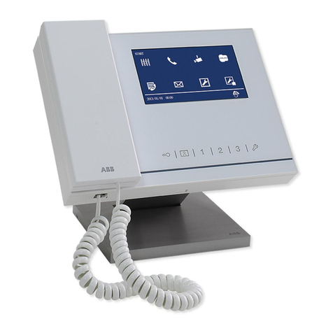
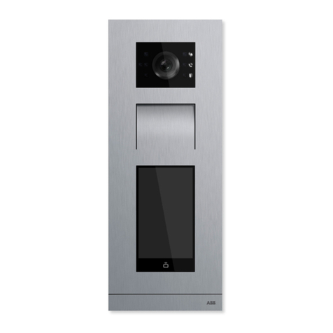
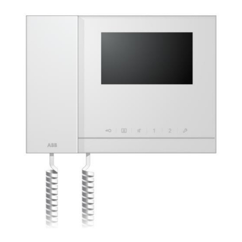
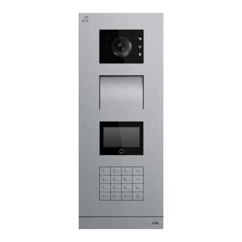
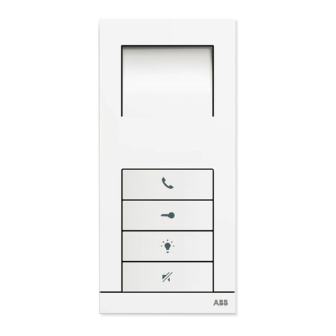
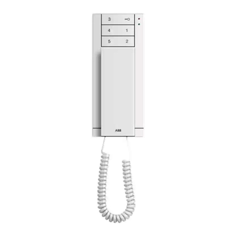
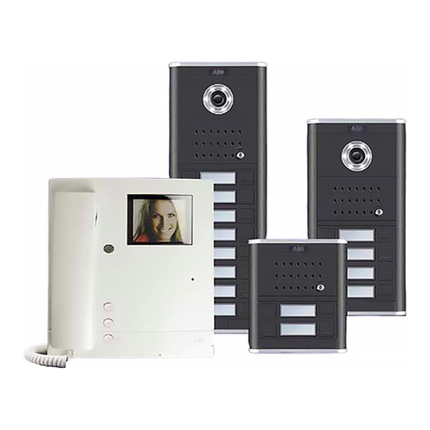
ABB W2153 BL User manual

• English
• Español
ABB-Welcome
—
Quick Guide - Audio Kit:
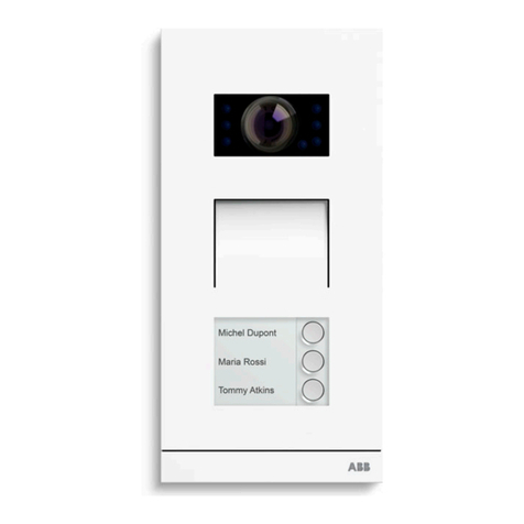
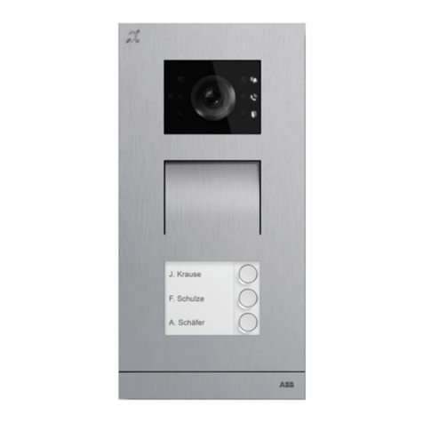
Audio Outdoor Station
Teléfono con auricular y
3pulsadores (W2153 BL)


—
Content
004 – 009
010 – 015
English
Español

4ABB-WELCOME AUDIO KIT
Cable
Coax, 75-5
Ø=0.75 mm,
0.45 mm²
RVV,
Ø=1 mm,
2 x 0.75 mm²
J-Y(ST)-Y,
Ø=0.8 mm,
2 x 0.5 mm²
J-Y(ST)-Y,
Ø=0.6 mm,
2 x 0.28 mm²
UTP 5, 2 x Two pairs,
each core
Ø=0.5 mm 8 x 0.2 mm²
A650 610 410 230 640
B200 190 130 70 200
—
English
Wiring
Lock connection
Type A Type B Type C
Distance
a b
a b
110-240 V
ON ON
M/S RC
Add=001
2-wire bus line 110-240 V
A
B
ab
Exit GND Lock COM NC NO ab
Exit GND Lock COM NC NO
PS
ab
Exit GND Lock COMNCNO
PS

QUICK GUIDE 5
Interface description
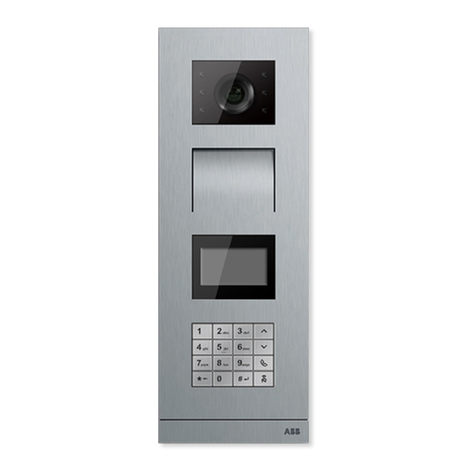
Audio module on the video aluminum outdoor station
No. Description
1 Connector for camera module
2 Connector for device software update
3 Plug-in clamps(COM-NC-NO) for floating output, door opener (30
V AC/DC 1 A)
4 Plug-in clamps(Lock-GND) for door opener (18 V 4A impulsive, 250
mA holding)
5 Plug-in clamps(DC-GND) for additional power supply
6 Plug-in clamps(a-b) for Bus connection
7 Connector for induction loop module
8 Connector for next module
9 Connector for exit pushbutton
10 Connector for sensor to check the door status
11 Rotary switch to set the address of OS (1-9)
12 Set feedback tone of push button: ON/OFF
13 Configure push button as single column or double columns
(ON= double columns; OFF= single column)
14 Configure function of 1st / 2nd push button
3->OFF, 4->OFF=call indoor station/call indoor station;
3->ON, 4->OFF=switch on lightings/call indoor station;
3->OFF, 4->ON=call guard unit / call indoor station;
3->ON, 4->ON=switch on lightings / call guard unit.
15 Adjust loudspeaker volume
16 Adjust door lock release time, 1-10 seconds
No. Description
1X100 X10 X1
Jumper to set the address of the indoor station.
Example: setting address 024
2Master /Slave function
Only one indoor station in each apartment must be set as “Master”
(Jumper should be set as ‘M/S on’). All additional indoor stations
in the same apartment must be set as “Slave” (Jumper should be
set as ‘M/S off’).
3Terminal resistor
In video installations or mixed audio and video installations, the
Jumper must be set as ‘RC on’ on the last device of the line.
4 a b = Bus connection
5 a potential free contact, such as a doorbell pushbutton
1 2
345678910
11
12
13
14
15
16
024
1
2
4
3
Indoor station
hundreds digits
X100
0
5

6ABB-WELCOME AUDIO KIT
Audio outdoor station installation
Operating Audio indoor station
Control elements
Audio indoor station installation
Unit:
mm
117
120
46
1
2
No. Description
1Handset
While a call is coming, pick up the handset to activate the commu-
nication within 30 seconds and hang up the handset to end the call.
2Unlock button
2A Open the door by pressing this button at any time.
2B Auto-unlock: the door is released automatically after incoming
call. To activate this function, long press this button for more
than 10 seconds until the blue LED is on. The same operation
will deactivate the funcition.
3Programmable button
3A Programmable for additional function, e.g. call guard unit,
intercom etc.
3B Default function of programmable button 1 is to release the 2nd
lock on the default outdoor station.
4Blue LED
4A LED light blue = auto-unlock function is enabled.
4B LED flashes slowly = an incoming call.
4C LED flashes quickly = the system is busy.
5Red LED
5A LED light red = mute function is enabled.
5B LED flashes slowly = a button is pressed.
5C LED flashes quickly = the door is open exceeding the set time (a
sensor must be connected).
6 Three-position selector to adjust ringtone volume
1
2
1
3
24
56

QUICK GUIDE 7
Unlock button, it is abbreviated as [Unlock].
Programmable button 1, it is abbreviated as [Program 1].
Programmable button 2, it is abbreviated as [Program 2].
2
1
Step Description Blue LED Red LED
1 In standby status, hold [Program 1] and [Program 2] for 3 seconds to
enter the setting mode.
2 Press [Unlock] repeatedly to select the ringtone.
3 Hold [Program 1] and [Program 2] for 3 seconds to save the setting
and exit the setting mode.
Step Description Blue LED Red LED
1 In standby status, hold [Program 1] and [Program 2] for 3 seconds to
enter the setting mode.
2 Press [Program 1] repeatedly to select the ringtone.
3 Long press [Unlock] for 3 seconds to set the “Repeated ringtone” function.
3A Repeated ringtones indicate the function is enable (default).
3B Once ringtone indicates the function is disable.
4 Hold [Program 1] and [Program 2] for 3 seconds to save the setting and
exit the setting mode.
Step Description Blue LED Red LED
1 Pick up the handset, hold [Unlock] for 3 seconds to enter the setting mode.
Flash times of red LED indicate the address of default outdoor station.
*If you don’t want to change the address, hang up the handset to exit the
setting mode.
2 Press [Unlock] repeatedly to change the address in the sequency (1->2->3-
>4->5->6->7->8->9->1).
3 Hold [Unlock] for 3 seconds or put down the handset to save the setting and
exit the setting mode.
Setting the ringtone for door bell
Setting the ringtone for outdoor station
Setting the address of default outdoor station
*In standby status, press [Unlock] to release the lock on default outdoor station.

8ABB-WELCOME AUDIO KIT
Unlock button, it is abbreviated as [Unlock].
Programmable button 1, it is abbreviated as [Program 1].
Programmable button 2, it is abbreviated as [Program 2].
[Setting button] = Programmable button being set currently.
2
1
Step Description Blue LED Red LED
1 In standby status, hold [Program 1] or [Program 2] for 3 seconds to enter the
setting mode.
2 Press [Program 1] repeatedly to select the function 5 in the sequency
(0->1->2->3->4->5->0).
x5
3 Hold [Setting button] for 3 seconds to save the setting and exit the setting
mode.
Step Description Blue LED Red LED
1 In standby status, hold [Program 1] or [Program 2] for 3 seconds to enter the
setting mode.
2 Press [Program 1] repeatedly to select the function 1 in the sequency
(0->1->2->3->4->5->0).
x1
3 Hold [Setting button] for 3 seconds to enter the address setting.
4 Press [Unlock] repeatedly to set the tens digit in the sequency (0->1->2->3-
>4->5->6->7->8->9->0). The value is indicated by the LED flash times.
*The value will be resetore to 0 when [Program 2] is pressed during the
setting.
5 Press [Program 1] repeatedly to set the units digit in the sequency (0->1->2-
>3->4->5->6->7->8->9->0). The value is indicated by the LED flash times.
*The value will be resetore to 0 when [Program 2] is pressed during the
setting.
6 Hold [Setting button] for 3 seconds to save the setting and exit the setting
mode.
Setting the programmable button to release the 2nd lock on default outdoor station
Setting the programmable button to release the designated switch actuator
*You need to set the address of default outdoor station before this function is operated.
Service
For European Union conturies:
ABB S.p.A - Viale dell’Industria 18, 20010
Vittuone (MI), Italy
For Non-EU conturies:
ABB Xiamen Smart Technology Co., Ltd.
No. 7 Fangshan South Road, Xiang An, Xiamen, Fujian 361000, China

QUICK GUIDE 9
Cable
Coaxial, 75-5
Ø=0.75 mm,
0.45 mm²
RVV,
Ø=1 mm,
2 x 0.75 mm²
J-Y (ST) -Y,
Ø=0.8 mm,
2 x 0.5 mm²
J-Y (ST) -Y,
Ø=0.6 mm,
2 x 0.28 mm²
UTP 5, 2 x dos pares,
cada núcleo
Ø=0.5 mm 8 x 0.2 mm²
A650 610 410 230 640
B200 190 130 70 200
—
Español
Cableado
Conexión de la cerradura
Type A Type B Type C
Distancia
a b
a b
110-240 V
ON ON
M/S RC
Añadir=001
Línea de bus de 2 cables 110-240 V
A
B
ab
Exit GND Lock COM NC NO ab
Exit GND Lock COM NC NO
PS
ab
Exit GND Lock COMNCNO
PS

10 ABB-WELCOME AUDIO KIT
Descripción de la interfaz
Módulo de audio en la placa de calle de vídeo de aluminio
N.º Descripción
1 Conector para módulo de cámara
2 Conector para actualización de software del dispositivo
3 Terminales de conexión (COM-NC-NO) para contacto libre de po-
tencial, abrepuertas (30V CA/CC 1ª)
4 Terminales de conexión (Lock-GND) para abrepuertas (18 V 4 A
impulsivos, 250 mA de mantenimiento)
5 Terminales de conexión (CC-GND) para fuente de alimentación
adicional
6 Terminales de conexión (a-b) para la conexión de bus
7 Conector para el módulo de bucle de inducción
8 Conector para el módulo siguiente
9 Conector para el pulsador de salida
10 Conector para el sensor de comprobación del estado de la puerta
11 Interruptor giratorio para establecer la dirección de la unidad
exterior (1-9)
12 Establecer los tonos de confirmación para pulsadores: ON/OFF
(ENCENDIDO/APAGADO)
13 Configurar los pulsadores en una columna simple o doble
(ENCENDIDO= columna doble; APAGADO= columna simple)
14 Configurar funciones de los pulsadores 1.º/2.º
3->APAGADO, 4->APAGADO=llamar a estación interior/llamar a
estación interior;
3->ENCENDIDO, 4->APAGADO=encender iluminación/llamar a la
estación interior;
3->APAGADO, 4->OENCENDIDO=llamar al puesto de guardia/llamar
a la estación interior
3->ENCENDIDO, 4->ENCENDIDO=encender iluminación/llamar al
puesto de guardia.
15 Ajusta el volumen del altavoz
16 Ajustar el tiempo de apertura de la cerradura de la puerta, 1-10
segundos
N.º Descripción
1X100 X10 X1
Puente para establecer la dirección de la estación interior.
Ejemplo: establecer la dirección 024
2Función maestro/esclavo
Se debe establecer solo una estación interior de cada apartamento
como «Maestro» (el puente debe establecerse como ‘M/S on’). El
resto de estaciones interiores del mismo apartamento deben fi-
jarse como “Esclavo” (el puente debe establecerse como ‘M/S off’).
3Resistencia terminal
En instalaciones de vídeo o instalaciones mixtas de audio y vídeo,
el puente debe establecerse como ‘RC on’ en el último dispositivo
de la línea.
4 a b = Conexión de bus
5 Contacto sin potencial, como el pulsador de un timbre
1 2
345678910
11
12
13
14
15
16
024
1
2
4
3
Indoor station
hundreds digits
X100
0
5
QUICK GUIDE 11
Instalación de la placa de calle de audio
Manejo de la estación interior de audio
Elementos de control
Instalación de la estación interior de audio
Unidad: mm
117
120
46
1
2
N.º Descripción
1Auricular
Al recibir una llamada, coja el auricular para activar la comunicación
en el plazo de 30 segundos y cuélguelo para finalizar la llamada.
2Botón de apertura «Unlock»
2A Pulse este botón para abrir la puerta en cualquier momento.
2B Apertura automática: la puerta se abre automáticamente tras
recibir una llamada. Para activar esta función, mantenga pulsa-
do este botón más de 10 segundos hasta que se encienda el LED
azul. La misma operación desactiva esta función.
3Botón programable
3A Programable para función adicional, p. ej. llamar al puesto de
guardia, intercomunicador, etc.
3B La función predeterminada del botón programable 1 es abrir la
2.ª cerradura de la placa de calle predeterminada.
4LED azul
4A LED azul encendido = función de apertura automática activada.
4B LED parpadea lento = llamada entrante.
4C LED parpadea rápido = es sistema está ocupado.
5LED rojo
5A LED rojo encendido = función de silenciar activada.
5B LED parpadea lento = se ha pulsado un botón.
5C LED parpadea rápido = la puerta está abierta más tiempo del
establecido (debe conectarse un sensor).
6 6Selector de tres posiciones para regular el volumen del tono de
llamada
1
2
1
3
24
56

12 ABB-WELCOME AUDIO KIT
Botón para abrir, abreviado como [Unlock].
Botón programable 1, abreviado como [Program 1].
Botón programable 2, abreviado como [Program 2].
2
1
Paso Descripción LED azul LED rojo
1 En modo de espera, mantenga pulsados [Program 1] y [Program 2] durante 3
segundos para acceder al 00 modo de ajuste.
2 Pulse [Unlock] varias veces para elegir el tono de llamada.
3 Mantenga pulsados [Program 1] y [Program 2] durante 3 segundos para
guardar la configuración y abandonar el modo de ajuste.
Paso Descripción LED azul LED rojo
1 En modo de espera, mantenga pulsados [Program 1] y [Program 2] durante 3
segundos para acceder al modo de ajuste.
2 Pulse [Program 1] varias veces para elegir el tono de llamada.
3 Mantenga pulsado [Unlock] durante 3 segundos para establecer la función
“Tono de llamada repetido”.
3A «Tonos de llamada repetidos» indica que la función está activada
(predeterminado).
3B «Tono de llamada único» indica que la función está desactivada.
4 4Mantenga pulsados [Program 1] y [Program 2] durante 3 segundos para
guardar la configuración y abandonar el modo de ajuste.
Paso Descripción LED azul LED rojo
1 Coja el auricular, mantenga pulsado [Unlock] durante 3 segundos para
acceder al modo de configuración.
El número de destellos del LED rojo indica la dirección de la placa de calle
predeterminada.
*Si no desea cambiar la dirección, cuelgue el auricular para abandonar el
modo de configuración.
2 Pulse [Unlock] varias veces para cambiar la dirección siguiendo la secuencia
(1->2->3->4->5->6->7->8->9->1).
3 Mantenga pulsado [Unlock] durante 3 segundos y cuelgue el auricular para
guardar los ajustes y abandonar el modo de configuración.
Establecer el tono de llamada del timbre
Establecer el tono de llamada de la placa de calle
Establecer la dirección de la placa de calle predeterminada
*En estado de espera, pulse [Unlock] para abrir la cerradura en la placa de calle predeterminada.

QUICK GUIDE 13
Botón para abrir, abreviado como [Unlock].
Botón programable 1, abreviado como [Program 1].
Botón programable 2, abreviado como [Program 2].
[Botón de ajuste] = Botón programable que se está configuración actualmente.
2
1
Paso Descripción Blue LED Red LED
1 En modo de espera, mantenga pulsados [Program 1] o [Program 2] durante 3
segundos para acceder al modo de ajuste.
2 Pulse [Program 1] varias veces para elegir la función 5 de la secuencia
(0->1->2->3->4->5->0).
x5
3 Mantenga pulsado el [Botón de ajuste] durante 3 segundos para guardar la con-
figuración y abandonar el modo de ajuste.
Paso Descripción Blue LED Red LED
1 En modo de espera, mantenga pulsados [Program 1] o [Program 2] durante
3 segundos para acceder al modo de ajuste.
2 Pulse [Program 1] varias veces para elegir la función 1 de la secuencia
(0->1->2->3->4->5->0).
x1
3 Mantenga pulsado el [Botón de ajuste] durante 3 segundos para acceder a la
configuración de la dirección.
4 Pulse varias veces [Unlock] para establecer el dígito de decenas de la se-
cuencia (0->1->2->3->4->5->6->7->8->9->0). El valor lo indica el número de
parpadeos del LED.
*El valor volverá a 0 al pulsar [Program 2] durante el ajuste.
5 Pulse [Program 1] varias veces para establecer el dígito de las unidades de
la secuencia (1->2->2->4->5->6->7->8->9->0). El valor lo indica el número de
parpadeos del LED.
*El valor volverá a 0 al pulsar [Program 2] durante el ajuste.
6 Mantenga pulsado el [Botón de ajuste] durante 3 segundos para guardar la
configuración y abandonar el modo de ajuste.
Configuración del botón programable para abrir la 2.ª cerradura en la placa de calle
predeterminada
Configurar el botón programable para abrir el actuador del interruptor designado
*Debe establecer la dirección de la placa de calle predeterminada antes de utilizar esta función.
Mantenimiento
Para países pertenecientes a la Unión Europea:
ABB S.p.A - Viale dell’Industria 18, 20010
20010 Vittuone (MI) Italia
Para países no pertenecientes a la Unión Europea:
ABB Xiamen Smart Technology Co., Ltd.
No. 7 Fangshan South Road, Xiang An, Xiamen, Fujian 361000, China

14 ABB-WELCOME AUDIO KIT
—
Note


—
For European Union conturies:
ABB S.p.A - Viale dell’Industria 18, 20010
Vittuone (MI), Italy
For Non-EU conturies:
ABB Xiamen Smart Technology Co., Ltd.
No. 7 Fangshan South Road, Xiang An,
Xiamen, Fujian 361000, China
www.abb.com
2TMU200000M0081100
© Copyright 2020 ABB. All rights reserved.
Specifications subject to change without notice.
Table of contents
Languages:
Other ABB Intercom System manuals

ABB
ABB Welcome M M2233 User manual

ABB
ABB M22381-W User manual

ABB
ABB 83210-AP-xxx-500 User manual

ABB
ABB 83220-SM-xxx-500 User manual

ABB
ABB H81381P Series User manual

ABB
ABB M22343 Series User manual

ABB
ABB M22001 series User manual

ABB
ABB ABB-Welcome M2240-W User manual

ABB
ABB H81402FR Series User manual

ABB
ABB Video kit User manual

ABB
ABB CM-06DN Series User manual

ABB
ABB Video Outdoor Station User manual

ABB
ABB M2231 SERIES User manual

ABB
ABB 83210-AP 500 Series User manual

ABB
ABB Welcome M2233 Series User manual

ABB
ABB Welcome User manual

ABB
ABB ABB-Welcome User manual

ABB
ABB H8137xPx-S User manual

ABB
ABB M22302 series User manual

ABB
ABB Welcome M2233 Series User manual