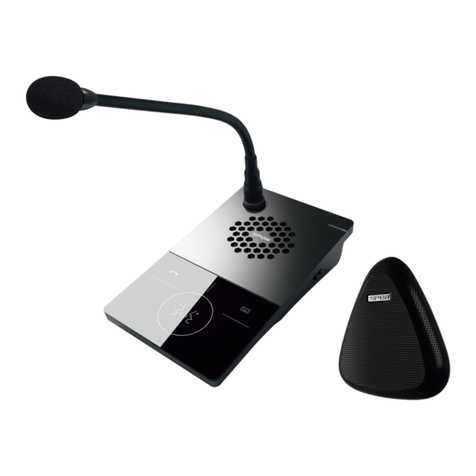
Spon XC-9031V User manual


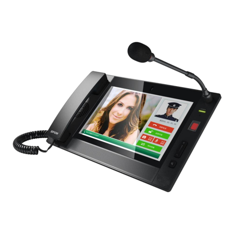
IP video intercom paging console user manual
Content
Summarize........................................................................................................................................................................................................ 1
Safety precaution .............................................................................................................................................................................................. 1
Product introduction .......................................................................................................................................................................................... 2
Features ............................................................................................................................................................................................................. 2
Hardware interface introduction ...................................................................................................................................................................... 2
Introduction...................................................................................................................................................................................................... 4
Packing list ......................................................................................................................................................................................................... 4
IP video intercom paging console installation ............................................................................................................................................... 5
Wiring picture ..................................................................................................................................................................................................... 6
Basic network setting........................................................................................................................................................................................ 6
Custom parameters........................................................................................................................................................................................ 7
Login web page ................................................................................................................................................................................................. 7
Basic setup ........................................................................................................................................................................................................ 8
Running status ......................................................................................................................................................................................... 8
Device parameters .................................................................................................................................................................................. 9
Server parameters ................................................................................................................................................................................... 9
Ta l k p a ra m e t e r s ..................................................................................................................................................................................... 10
Broadcast parameters ........................................................................................................................................................................... 10
Monitor parameters ............................................................................................................................................................................... 10
SIP parameters ...................................................................................................................................................................................... 11
Te r m i n a l se t t i n g ............................................................................................................................................................................................... 11
Off-line parameters ................................................................................................................................................................................ 11
External video......................................................................................................................................................................................... 12
Advanced setup............................................................................................................................................................................................... 12
System setting ........................................................................................................................................................................................ 12
User manage .......................................................................................................................................................................................... 12
Firmware upgrade ................................................................................................................................................................................. 13
System log .............................................................................................................................................................................................. 13
Interface description ....................................................................................................................................................................................... 14
Te r m i n a l l is t s e t t i n g ......................................................................................................................................................................................... 14
Group list setting ............................................................................................................................................................................................. 15
Basic function................................................................................................................................................................................................ 15
Ta l k .................................................................................................................................................................................................................... 15
Call transfer ...................................................................................................................................................................................................... 17
Monitor .............................................................................................................................................................................................................. 18
Broadcast ......................................................................................................................................................................................................... 20
Setting............................................................................................................................................................................................................... 22
View .................................................................................................................................................................................................................. 25
Favorite ............................................................................................................................................................................................................. 26
Ta l k r e c o r ds ...................................................................................................................................................................................................... 27
Other functions ................................................................................................................................................................................................ 28
Fault exclude.................................................................................................................................................................................................. 28
Copyright Announcement........................................................................................................................................................................... 29

IP video intercom paging console user manual
Summarize
Safety precaution
Please abide by the warning and the relevant safety tips.
Please take this manual in convenient place after you reading the guide for future reference.
Warning
The sign means there is potential safety hazard, when operate wrong may result in death or serious injury.
The sign is used to remind the user that attached is the important operation and maintenance data.
Setting and Installation
(1)Avoid being wet with the water.
Don’t make the machine or exposed to rain water or other liquid contamination of the environment, or lead to fire or get an
electric shock.
(2)Don’t use unspecified voltage.
Using the marked voltage on the machine.
Using more than the logo of voltage could lead to fire or shock.
(3)Don’t scratch the power cord.
Don’t scratch the power cord or cut it.
Simultaneous, keep the power line far way from heated objects, put heavy things on it will lead to fires or electric shock.
Using machine
(1)In case of the anomalies
Please turn off the power supply immediately when finding the abnormal phenomena, please connect with the agency. if you
continue to use, it will likely fires or shock.
·The smoke or odor of the machine.
·The inside of the machine is flooded by water or foreign bodies intrusion.
·Machine falling or machine shell damage.
·The power cord damage (wire core is exposed of broken, etc)
·Fault (eg it can’t network, no sound ect)
(2)Don’t open the machine internal or modify the machine.
Do not let foreign matters invade the machines internal.
Don’t let the metal items or inflammable objects inserting machine such as foreign inserting machines or throw into the vents
machines internal, otherwise will likely cause fires or electric shock.
(3)Please do not touch it when thundering
To a v o i d e le c t r i c s h o c k , p l e a se d o n o t t ou c h t h e m a c h in e a n d t h e p l u g w h e n l i g ht n i n g , e t c .
(4)Please do not place containers with liquid or small metal objects on machine above.
If gets upset containers, and let the fluid inflow to the machine that will likely fires or cause shock.
(5)Do not open the machine internal or modify the machine.
The machine internal contains high voltage parts, once open the cover or modify the machine, it will likely fires or cause shock.
All the maintenance and other machine modification should be operated by professional personnel.
(6)Maintenance and the precautions for not using in a long time.
While maintenance, if the machine is not using for 10 days or more, please shut off power supply switch for safety. If do not
comply with this provision, it will likely cause electric shock or fires.
1

IP video intercom paging console user manual
Product introduction
IP video intercom paging console built-in independent intellectual property rights IP Audio digital network technology,
equipped with power input interface, SD card interface ( TF card interface ), audio input output interface, RJ45 network interface,
built-in CMOS color camera and so on.
Features
Professional console design, can be installed placement of desktop, hanging and embedded.
With a 10.1 inches digital image display, capacitive touch screen, resolution ratio 1280 * 80.
The built-in HD 5 million pixels digital camera, support two-way video calls, using H. 264 coding.
Built-in 3W speakers and microphones, used for hands-free calls, receive broadcast and monitoring (digital noise reduction)
It can broadcasting to all groups, group, individual terminal.
File broadcast and pre-recording broadcast function, the local audio files or recording can broadcast to designated terminal.
With a red emergency button, support one key broadcasting to the preset group.
Support incoming /outgoing calls display function, incoming calls voice broadcasting.
Call transferring function, support busy transferring, manual transferring, non-response transferring and so on.
Support circular surveillance/monitoring terminal, contents are stored in server, support local browse queries.
Compatible with the standard SIP protocol, it can separately access into VOIP phone system (such as an Asterisk
mainstream, IP-PBX).
Support offline intercom without server.
To c h e c k th e w o r k i n g s ta t e o f t h e o t h e r t e r m in a l s ( l o g i n s ta t u s , i n t e r c o m s t a t u s , t a s k s t a t u s ) .
Removable microphone pole, support microphone mode, receiver mode, hands-free mode.
HDMI interface, it can outside connect the display to output the high-definition picture;
Support different screen display: when during the video intercom, IP video intercom paging console display video pictures,
outside connect the display screen to display the electronic map.
With 1 road alarm output and 1 road alarm input interface, trigger outside connection lights and accept linkage.
Standard RJ45 network interface, can access if there is a Ethernet, support across the network segment and route.
Hardware interface introduction
Front
2

IP video intercom paging console user manual
①Microphone pole socket: insert the microphone pole, collecting audio.
②Working indicator: offline status is red, device has logined to the sever is green.
③Reset interface: it can be reset with tweezers.
④Emergency broadcast: press "emergency" button for 1 second, it can broadcast to the all groups.
⑤Volume control button.
⑥Mute button.
⑦Microphones: collecting local intercom audio in hands-free mode.
⑧Loudspeaker: restore the remote site.
⑨Camera: collect local video.
○
10To u c h s c r e e n : m a n -machine interaction input channel, accept the command to input.
Back
3

IP video intercom paging console user manual
①HDMI interface: connect the display, high-definition HDMI video output.
②Network interface: insert the cable, connect to the server.
③Short circuit input/out interface: it can outside connect with other devices to linkage control.
④Power interface: connect with power DC12V / 2
⑤Line output interface
⑥Line input interface
⑦The receiver interface
⑧USB interface
⑨SD card slot
○
10Camera: adjust the camera Angle
Introduction
Packing list
IP video intercom paging console including the following fittings, please examine the fittings before the installation, if any
missing, please contact the distributor.
(1) IP video intercom paging console 1set
(2) Microphone pole 1 pc
(3) Power adapter (DC12V/2A)1pc
(4) Installation manual 1pc
(5) Certification and warranty card 1 PC
4

IP video intercom paging console user manual
IP video intercom paging console installation
(1) Install the microphone pole groove aim at corresponding pedestal groove, as following picture:
(2)Tightening knob direction as following picture.
5

IP video intercom paging console user manual
Wiring picture
Basic network setting
Connected IP video intercom paging console and power on. Please revise the console parameters as per the live
environment, there have below 2 methods:
Touch screen operation
(1)Select “Setting” option, then enter the password(the default is 123456) and click “OK”.
6

IP video intercom paging console user manual
(2)Then select the “Network” to set the device ID, local IP, local port and server IP address. etc these information.
(3)Click “Save”, the IP address setting is valid now(Note: the device ID No and IP address can`t be same with other
terminals).
Web page operation
Enter into the IP video intercom paging console web interface, then modify the parameters according to the environment,
after setting completed, click “save”.
Please refer to the custom terminal network parameters setting for detailed operation .
Custom parameters
Login web page
(1)Please input the video paging console IP address to the browser address column (the factory default IP address is
192.168.1.101), then enter.
(2)Enter the user name(admin) and password(123456) in the web page.
7

IP video intercom paging console user manual
(3)Click OK to enter the IP video intercom paging console Web page.
Basic setup
Running status
Display the device IP address, server IP address, MAC address...etc.
8

IP video intercom paging console user manual
Device parameters
Network parameters list as below:
Device port It can`t revise without the special situation(the default is 2046).
Device IP Device local IP address, the default is 192.168.1.101
Subnet mask The terminal subnet mask.
Default gateway The terminal default gateway.
Preferred DNS The terminal network preferred domain name interpreter IP.
Server parameters
Device ID The only identify NO. For device, it can`t repeat with other terminals.
Server IP IP video intercom paging console logined server address
9

IP video intercom paging console user manual
Talk parameters
The user can set to display the favorites, dial plate, talk records or not, it also can set to call display the video and open the built-in
Mic function or not.
Broadcast parameters
The user can set to open the broadcast function or not from this interface.
Monitor parameters
10

IP video intercom paging console user manual
The user can set to open monitor function or not, it also can assign the loop monitor time interval.
SIP parameters
The user can set to open the SIP function or not from this interface.
Terminal setting
Off-line parameters
The user can set each terminal`s corresponding off-line talk target and device port from this interface.
Note: The device port is suggested to use the default setting 2043(unless there have special circumstance)
11

IP video intercom paging console user manual
External video
IP video intercom paging console can check IP camera`s video, the method as below:
This interface list each terminal binding IP camera, the user need fill each terminal corresponding IP camera IP address, user
name and password.
When the IP video intercom paging console is talking with terminal(it`s already binding the IP camera), it can check the
corresponding IP camera video from IP video intercom paging console.
Advanced setup
System setting
Language: IP video intercom paging console support both English and German.
Reboot: Manually reboot.
Factory rest: All of parameters will be covered to the factory setting.
User manage
The user can revise the login Web page account and password from this option.
12

IP video intercom paging console user manual
Firmware upgrade
It can check the IP video intercom paging console program version from this interface.
System log
IP video paging console can auto-recording and make the log, it also support the user to drive out the system log.
13

IP video intercom paging console user manual
Interface description
: terminal status icon
Icon
(
color
)
Terminal status
Blue Te r m i n a l l o g i ne d t o s e r v e r
Grey Te rminal haven`t login to server
Cable discount
:IP video intercom paging console volume
Terminal list setting
It can custom each terminal name from server terminal setting, please refer to the server software operation manual for
details.
14

IP video intercom paging console user manual
Group list setting
It can custom each group name from server terminal setting as per the situation, please refer to the server software
operation manual for details.
Basic function
Talk
(1)One-click calling
After select “Talk”, click the target terminal, the IP video paging console will auto-call to the target terminal.
15

IP video intercom paging console user manual
(2)Dialing
Under talk mode to choose “Dial” will popup the digital keyboard, enter the target ID No and click call button, it will call to the
target terminal.
Dialing mode support call to the panel, enter the target terminal NO.# panel No., then click calling button to talk with
panel,eg:”1#7”means to call the panel 7 under terminal 1.
Close video and audio
The user can set to close or open the IP video intercom paging console video and audio.
Remote open the door
16

IP video intercom paging console user manual
Click ”Unlock” within the conversation, IP video intercom paging console can control the other party to open the electric
doorlock.
Click the other party video picture it can become the full-screen mode within the conversation, and click again it will become the
last mode.
Note: Only the terminal with the camera support video conversation.
Call transfer
Manually transfer
Select call transfer within the conversation, enter the target terminal ID NO.and click OK button, the IP video intercom paging
17

IP video intercom paging console user manual
console will discount the present terminal talk, and it will auto-transfer to the transfer target.
NO response transfer
It need make some setting from sever for No response transfer;
Select server advance setting, enter password(the default is 123456),from the parameters1 to choose”Enable call
non-response shift” and set the time, then click OK to restart the server.
When there is no response, the IP video intercom paging console will transfer to the server preset 1st mapping target.
Busy transfer
When the target is busy, the IP video intercom paging console will transfer to the server preset 2nd mapping target.
Monitor
IP video intercom paging console can monitor one terminal or all of the terminal under one server, and the user need select
18
Other manuals for XC-9031V
2
Table of contents
Other Spon Intercom System manuals
Popular Intercom System manuals by other brands
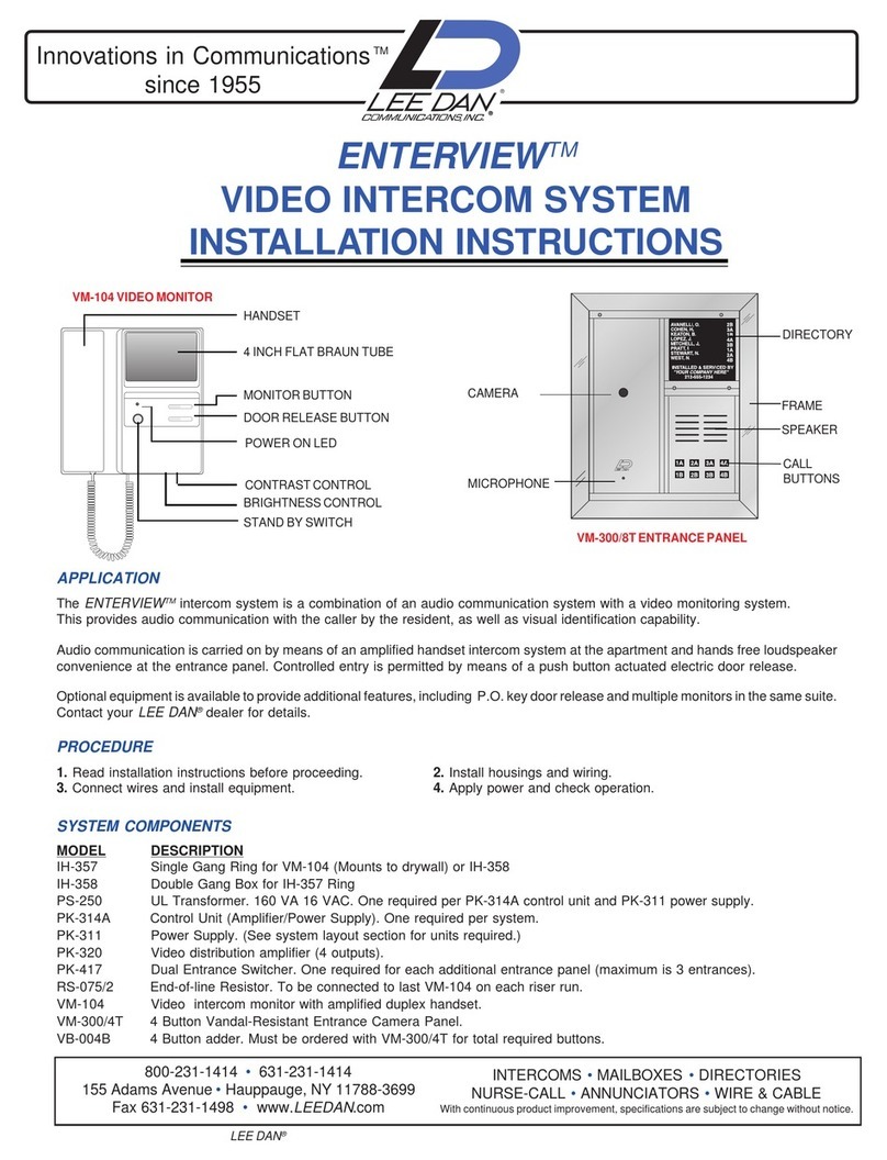
lee dan
lee dan enterview installation instructions
Alcad
Alcad 980 Series manual

Federal Signal Corporation
Federal Signal Corporation E1 Nstallation and service instructions
Fermax
Fermax Cityline Programming manual
Amroad
Amroad XL COMMUNITY STATION installation manual

Comelit
Comelit KAE5061 Technical instructions

