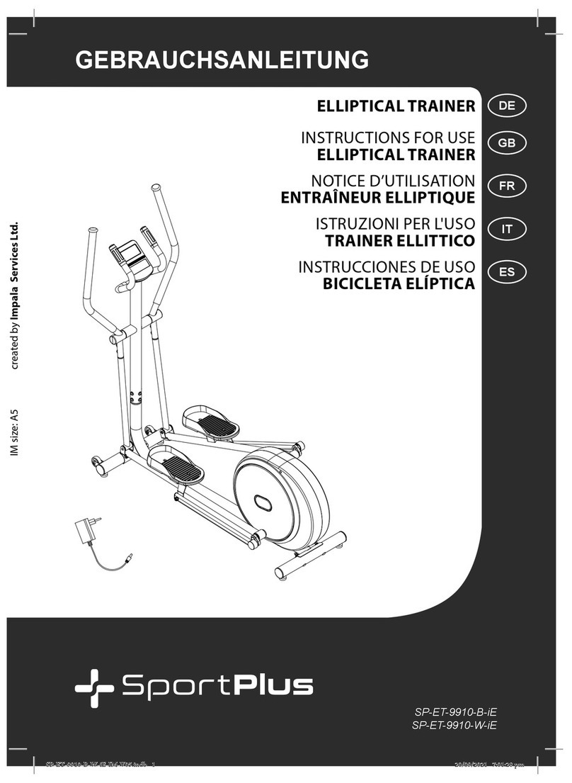
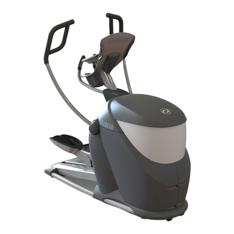
Sportplus SP-ET-7000-iE User manual

!"#$"%&%'()%*"$+&%'
!"#$%#&'''#($
!"#$%$&$'(#)*
,-.((+-)$%"-
+,-.#")/+)0
,-.((+-)$%"-
"12-#23-"401!
,-.((/+-)$%"-012*./"**$3+$4&"
")/+)0-#+5-/5-
,-.((+-)$%"-
")/+)0#2-#!/,5.+66!1/-,
,-.((+-)$%"-
GB
FR
IT
ES
DE
SP-ET-7000-iE-INT-V04.indb 1 25/1/2018 6:35 PM

29
!"#$%&'
Dear Customer,
Congratulations for choosing a SportPlus product. We have every expectation that you
will be fully satisfied with your new purchase.
To guarantee optimal function of this product, please adhere to the following instructions:
• Before using this product for the first time, please read the manual carefully!
•
The product has been designed with safety features. Nevertheless, please read the safety
instructions carefully and use the equipment only as described in the manual to avoid
hazards and personal injury.
• Please retain this manual for future reference.
• Should you pass on this product, ensure to include the corresponding instruction manual.
CONTENTS
1. TECHNICAL DATA ......................................................................................................................................... 29
2. SAFETY INSTRUCTIONS....................................................................................................................... 30
3. PART LIST ......................................................................................................................................................... 33
4. EXPLOSION VIEW.......................................................................................................................................... 36
5. ASSEMBLY INSTRUCTIONS ...................................................................................................................... 37
6. USING THE COMPUTER.............................................................................................................................. 44
7. TROUBLESHOOTING ................................................................................................................................... 53
8. MAINTENANCE, CLEANING AND CARE ............................................................................................... 53
9. NOTES ON DISPOSAL.................................................................................................................................. 53
10. SERVICE AND REPLACEMENT PARTS.................................................................................................... 54
11. WARRANTY ..................................................................................................................................................... 55
1. TECHNICAL DATA
PRODUCT INFORMATION
Dimensions (W x H x D): 165 x 63 x 178 cm
Total weight: approx. 130 kg
Class: H.A. (Domestic use), EN 957-1, EN 957-5
Maximum user weight: 130 kg
Computer information
Model: TZ-2175
Computer functions: Time, speed, distance, approx. calorie consumption,
odometer, pulse recovery
Technical data for power adapter
Input voltage: 100 V-240 V~ 50/60 Hz
Output voltage: 9V , 1000 mA, 9W
SP-ET-7000-iE-INT-V04.indb 29 25/1/2018 6:36 PM

30
2. SAFETY INSTRUCTIONS
INTENDED USE
•
This product is intended for private use and is not suitable for medicinal, therapeutic or
commercial purposes.
• The maximum permissible weight of a person using this product is 130 kg.
•
Before connecting the device to the mains, make sure the current and mains voltage match
the specifications on the rating label.
• Never use the device if damaged! Disconnect the device from the mains and contact your
customer service, if the device has been damaged in any way.
•
Avoid damaging the cable by jamming, bending or rubbing it on sharp edges. Keep it away
from hot surfaces and open flames.
• Guide the cable in such a way that it cannot be pulled down or tripped over accidentally.
• When using an extension cable, it must be suitable for the respective power used.
•
Warning! Never immerse electric parts of the device in water or other liquids during cleaning
or use. Do not hold the device under running water.
•
Never operate the device with wet hands or when standing on a wet floor. Never touch the
mains plug with wet or moist hands.
•
The use of accessories not explicitly recommended by the manufacturer could cause injuries
and damage. Only use original accessories.
• Keep the device away from hot surfaces and open flames. Always use the device on a flat,
stable, clean and dry surface. Protect the device against extreme heat, dust, direct sunlight,
moisture, and dripping and splashing water.
• Do not place any heavy objects on the device. Do not place any objects with open flames
(e.g. candles) on or next to the device. Do not place any objects filled with water (e.g. vases)
on the device.
•
This device is not intended to be used by persons (including children) with reduced physical,
sensory or mental abilities or lack of experience and / or lack of knowledge unless they are
supervised by a person responsible for their safety or have received instructions on how
to use the device.
•
Do not pull the cord when disconnecting the adapter from the wall socket and do not wind
the mains cable around the device.
•
Connect the adapter to a readily accessible wall socket in order to be able to disconnect the
device from the mains immediately in case of emergency. Disconnect the adapter from the
wall socket to fully switch offthe device. Use the adapter as disconnecting device.
•
Disconnect the adapter before each cleaning and if not using the device for a longer period
of time.
• Only use the adapter included in the delivery scope.
SP-ET-7000-iE-INT-V04.indb 30 25/1/2018 6:36 PM
31
!"#$%&'
DANGER FOR CHILDREN
•
Batteries could be fatal if swallowed. For this reason, store batteries out of the reach of
children. If a battery has been swallowed, seek medical attention immediately.
•
Children cannot recognize the hazards that this product may pose. For this reason, keep
this product out of the reach of children. The product is not a toy. Store the product at a
location out of the reach of children and pets.
•
Parents and supervisors should be aware of their responsibility, since, due to children's
natural playfulness and love of experimentation, situations and conduct will likely arise for
which the training unit is not intended.
•
If you allow a child to use the product, do not leave it unattended during use. Make all
necessary adjustments to the product yourself and supervise the child during exercise.
• Keep packaging materials out of the reach of children. They pose a suffocation hazard!
CAUTION RISK OF INJURY
•
Do not use the product if it is damaged or defective. In this case, contact a professional
workshop or our customer service.
•
Always verify that the product is in impeccable condition before use. Defective components
must be replaced immediately as failure to do so may impair the functioning and safety
of the unit.
• Make sure that no more than one person uses the product at a time.
•
Always use the product on a horizontal, level, nonslip and solid surface. Never use the
product near water and make sure there is a safety clearance of at least one meter on both
sides and two meters behind the product.
• Prevent your arms and legs from coming near the product's moving components.
• Do not put any objects into any openings on the product.
CAUTION PRODUCT DAMAGE
•
Do not alter the product in any way and use only original replacement parts. Have all repairs
carried out in a professional workshop or from similarly qualified persons - improper repairs
can lead to serious risks for the user. Use the product for the intended purposes as described
in the operating instructions only.
• Shield the product from spraying water, moisture, high temperatures and direct sunlight.
SP-ET-7000-iE-INT-V04.indb 31 25/1/2018 6:36 PM

32
INFORMATION ON ASSEMBLY
•
The product should be carefully assembled by a responsible adult. Ask for the assistance of
another, technically-skilled person in case of doubt.
•
Before beginning assembly of the product, read all assembly steps carefully and review
the diagram.
•
Remove all packaging materials and lay out all the parts.This will give you a good overview
and simplify assembly. Shield the assembly surface from filth and scratching by laying down
suitable padding.
•
Check the components against the components list to make sure all are present. Do not
dispose of all packaging materials until assembly is completed.
• Please note that there is always a risk of injury when using tools to carry out manual tasks.
Therefore, please exercise caution when assembling this product.
• Make sure your work environment is hazard-free. For example, do not leave any tools lying
around. Place the packaging materials somewhere where they will not pose any hazards
during assembly. Packaging foil or plastic bags pose a suffocation hazard for children!
•
After assembling the product according to the instructions, make sure that all screws, bolts
and nuts are installed correctly and tightened.
•
If necessary, lay out protective padding (not included) beneath the product to protect your
floor as there is no guarantee that, for instance, the rubber feet will not leave marks behind.
SP-ET-7000-iE-INT-V04.indb 32 25/1/2018 6:36 PM

33
!"#$%&'
3. PART LIST
No. Description
Quantity
1LUpper pedal tube, left 1
1RUpper pedal tube, right 1
2Screw 4
3Upper computer cable 1
4Computer 1
5Handlebar foam grip 2
6Self-tapping screw 2
7Cover cap (handle) 2
8Hand pulse cable 1
9Self-tapping hex screw M8x20 6
10 End cover 2
11 Foam cover 2
12 Hand pulse sensors 1
13 Fixed handlebar 1
14 Cross bar 1
15 Flat Washer 2
16 Curved washer 28
17 Hexagon socket screw 32
18 Connector 10
19 Flat Washer 4
20 Spring washer 38
21 Nut M10 2
22 Nut 2
23 Washer (C-shaped) 1
24 Wave washer 2
25 Ball bearings 1
26 Flywheel 1
27 Flywheel axle 1
28 Ball bearings 1
29 Belt adjustment 2sets
30RChain cover, right 1
31LCover cap, front 1
31RCover cap, rear 1
No. Description
Quantity
32 Plastic cover 1
33 Hexagon socket screw M8x55
mm 2
34 Flat Washer 10
35 Front Stabilizer 1
36 Round head screw M5x15 6
37 Screw M5x15 6
38 Washer (C-shaped) 1
39 Flat Washer 2
40 Spring 1
41 Round head screw M4x15 4
42 Lever holder 1
43 DC line 1
44LLower swivel rod, right 1
44RLower swivel rod, left 1
45 Screw M5x12 4
46 Motor 1
47 Frame 1
48 Lower computer cable 1
49 Support frame 1
50 Sensor 1
51 Flat Washer 1
52 Flat Washer 1
53 Flat Washer 3
54LPlastic cover (lower swivel
rod, left) 2
54RPlastic cover (lower swivel rod,
right) 2
55 Belt wheel 1
56 Belt 1
57 Pedal Axle 1
58 Self-tapping hex screw M8x15 4
59 crank 2
60 Round cover 2
SP-ET-7000-iE-INT-V04.indb 33 25/1/2018 6:36 PM

34
No. Description
Quantity
61 Screw M5x15 4
62 Screw M5x12 4
63 Connection lever (50 mm)
chain cover 1
64 Self-tapping screw M4.5x25 4
65 Connection lever (90 mm)
chain cover 2
66 Hexagon socket screw M8x20 8
67LPedal, left 1
67RPedal, right 1
68 Hex screws M10x78 2
69LPedal tube, left 1
69RPedal tube, right 1
70 Tube spacer 2
71LPedal tube, left 1
71RPedal tube, right 1
72 M element 2
73 End cover 2
74 Rear Stabilizer 1
75 Nut M10 3
76 Idle axle 1
77 Idle 1
78 Screw M6x12 1
79 Washer (C-shaped) 2
80 Magnetized axle 1
81 Magnet mount 1
82 Spring washer 2
83 Screw M62
84 Ball bearings 2
85 Wave washer 1
86 Flat Washer 2
87 Connector 4
88 Nut M10 2
89 Connector 4
No. Description
Quantity
90 Tube spacer 2
91 Flat Washer 2
92 Cover 2
93 Hex screws M8x70 2
94 Adjustable wheel 4
95 Cover cap, rear 2
96 Connection tube 1
97 Hex screws M8x75 2
98 Wave washer 4
99 Wheel 2
100 Ball bearings 4
101 Nut 4
102 Mounting plate 2
103 Cable 1
104 Sliding rail 2
105 Hex key 2
106 Multi-function tool 1
107 Adaptor 1
108 Hexagon socket screw M8x50 2
109 Connector 4
110 Cover cap (rear cable hole) 1
111 Nut (M10)4
112 Flat Washer
Φ16.5×Φ25×2mm 2
3. PART LIST
SP-ET-7000-iE-INT-V04.indb 34 25/1/2018 6:36 PM

35
!"#$%&'
3. PART LIST
FIXTURES
The following parts are required for assembling the device. Check
the fixtures set for completeness before assembly. Additional fixtures are premounted to the
product’s screw holes and must be loosened for the appropriate assembly step.
Hexagon socket screw M8x20 (17)
Spring washer (20)
Flat washer (34)
6pcs. each
Hexagon socket screw M8x20 (9)
Curved washer (16)
6pcs. each
Hexagon socket screw M8x20 (9)
Flat washer (19)
Spring washer (20)
2pcs. each
Hexagon socket screw M8x20 (9)
Curved washer (16)
Spring washer (20)
4pcs. each
Hexagon socket screw M8x20 (66)
8pcs.
Hexagon socket screw M8x55 (33)
Flat washer (34)
2pcs. each
Hexagon socket screw M10x78 (68)
Flat washer (53)
Nut M10 (75)
2pcs. each
!!!!
!!!!
!!!!
!!!!
!!!!
!!!
!!!
!!!!
!!!!
!!!!
!!!!
!!!!
!!!!
!!!!
!!!!
!!!!
!!!!
!!!
!!!
!!!!
!!!!
!!!!
!!!!
!!!!
Hex key
1pcs.
Hex key
1pcs.
Multifunctional tool (106)
1pcs.
SP-ET-7000-iE-INT-V04.indb 35 25/1/2018 6:36 PM

36
4. EXPLOSION VIEW
SP-ET-7000-iE-INT-V04.indb 36 25/1/2018 6:36 PM

37
!"#$%&'
5. ASSEMBLY INSTRUCTIONS
Take all parts out of the packaging carefully and place them on a flat surface. When doing this,
use suitable padding to protect the working surface. Assembly of the individual parts should
be carried out by 2people!
Before assembly, check the parts list to verify that all parts are present.
STEP 1:
48
35
47
33
34
74
34
20
17
104
93 20 16
94
96
1.
Fasten the lower tubes (104) to the rear stabilizer (74). Fasten with 12 sets of hex screws (17),
spring washers (20) and washers (34).
2.
Connect the lower tubes (104) with a cross tube (96). Fasten with 2sets of hex screws (93),
spring washers (20) and bent washers (16).
3. Fasten the rear stabilizer (74) to the main frame (47). Fasten with 4sets of hex screws (17),
spring washers (20) and bent washers (16).
4.
Fasten the front stabilizer (35) to the main frame (47). Fasten with 2sets of hex screws (33)
and washers (34).
SP-ET-7000-iE-INT-V04.indb 37 25/1/2018 6:36 PM

38
5. ASSEMBLY INSTRUCTIONS
STEP 2:
17 16
3
20
49
3
48
32
17
16
20
47
48
49
47
1. Attach the cover cap (32) to the support tube (49).
2.
Connect the computer cables (3, 48). Insert excess cable into the interior of the front
support tube (49).
Note: We recommend 2persons assembling the product. One person can hold the support
tube (49) while the other connects the cables (3, 48).
3. Place the support tube (49) to the main frame (47). Fasten with 6sets of hex screws (17),
spring washers (20) and bent washers (16).
SP-ET-7000-iE-INT-V04.indb 38 25/1/2018 6:36 PM

39
!"#$%&'
5. ASSEMBLY INSTRUCTIONS
STEP 3:
3
20
19
15
14
49
44L
44R
9
1. Insert the swivel uptake (14) into the support tube (49).
2.
Fasten the lower swivel rods (44 R/L) to the left axle of the front rod (22). Fasten with 2sets
of hex screws (9), bent washers (16) and spring washers (20). Now tighten the hex screws (9).
Caution! Please note the following when assembling the swivel rods (44 R/L):
• The swivel rods are marked with L for left and R for right.
• Fasten the hex screws so the pedal tubes are not blocked.
SP-ET-7000-iE-INT-V04.indb 39 25/1/2018 6:36 PM

40
5. ASSEMBLY INSTRUCTIONS
STEP 4:
3
44L
49
44R
59
919
71L
20
36
94
104
36
92
20
19
71R
9
1.
Fasten the pedal tubes (71 L/R) to the left and right crank (59). Fasten with 2sets of hex
screws (9), bent washers (16) and spring washers (20).
2. Place on the cover caps (92). Secure with 2round-head screws (36).
3. Place the pedal tubes (71 L/R) next to the lower tubes (104).
SP-ET-7000-iE-INT-V04.indb 40 25/1/2018 6:36 PM
41
!"#$%&'
5. ASSEMBLY INSTRUCTIONS
STEP 5:
13
69L
71L
69R
53 54R
36
69R 68
54L
44R
9
16
49
102 20 34 17
71L
44R
20
17
16
49
44L 13
71R
69L 69L
1L
1R
!
"
#
$
%
112
112
1.+2. Connect the pedal rods (69 L/R) to the lower pedal tubes (44 L/R). 1mounting plate (102) is
needed each for the left and right side. Secure with 2sets of hex screws (68), washers (53,112)
and nuts (75) [see Illustration 1/2].
3. Place on the cover caps (54 L/R). Secure with 4round-head screws (36) [see Illustration 3].
4. Mount the fixed handle (13) to the front rod (49). Secure with 2sets of hex screws (9) and
bent washers (16) [see Illustration 4].
5. Connect the upper pedal tubes (1R/L) to the lower pedal tubes (44 R/L). Secure with 4sets
of hex screws (17), bent washers (16) and spring washers (20) [see Illustration 5].
SP-ET-7000-iE-INT-V04.indb 41 25/1/2018 6:36 PM
42
5. ASSEMBLY INSTRUCTIONS
STEP 6:
69L
67L
66
1. Mount the pedals (67 L/R) to the pedal rods (69 L/R). Secure with 8hex screws (66).
SP-ET-7000-iE-INT-V04.indb 42 25/1/2018 6:36 PM
43
!"#$%&'
5. ASSEMBLY INSTRUCTIONS
STEP 7:
3
4
8
2
1. Loosen the 4screws (2) on the back of the computer (4).
2.
Connect the computer cables (3, 4). Insert excess cable into the interior of the support
tube (49).
3. Fasten the computer with the previously loosened screws (2) to the computer bracket on
the support tube (49).
The device is then fully assembled.
SP-ET-7000-iE-INT-V04.indb 43 25/1/2018 6:36 PM

44
6. USING THE COMPUTER
BODY
FAT
START
STOP
ENTER
DOWN
UP
PULSE
RECOVERY
CONTROLS/
CONNECTIONS
FUNCTION
START/STOP button •
Quick start function for starting the computer without
selecting a program in manual mode.
• Stop the workout mode.
• Start the workout.
UP button • Increase the resistance level during workout.
•
In setting mode: Increase the values for time, distance,
calories and age, or select a program and gender.
DOWN button • Reduce the resistance level during workout.
•
In setting mode: Decrease the values for time, distance,
calories and age, or select a program and gender.
ENTER button • In setting mode: Confirm currently entered data.
•
In stop mode: Press and hold for 2seconds to reset all
values to“0”or to default respectively.
BODY FAT button • Calculate the body fat ratio based on data to be entered.
PULSE RECOVERY button • Start the recovery pulse measurement.
SP-ET-7000-iE-INT-V04.indb 44 25/1/2018 6:36 PM

45
!"#$%&'
6. USING THE COMPUTER
CONTROL VIA CARIOFIT APP
•
You can connect the computer via Bluetooth® 4.0with your smartphone/tablet. Please
download the “Cardiofit” app from the Google Play Store for Android or the Apple App
Store for iOS.
IMPORTANT DISPLAY INDICATIONS
TIME
Shows workout time in minutes and seconds.The computer automatically
counts the minutes from 0:00 to 99:59.
DISTANCE Shows the distance covered during workout (range 0-99.9km).
RPM Shows the current pedaling frequency (rounds/minute).
WATT Shows the value of mechanical energy generated during workout.
SPEED Speed (km/h)
CAL Shows the calories consumed during training. This is an estimated value.
PULSE
Automatically registers and shows the corresponding heart rate during
training. In order to measure your pulse, place your palms on both contact
surfaces (18); the computer will display your current pulse per minute.
IMPORTANT NOTES PRIOR TO WORKOUT
MAINS INLET
•
Connect the adapter (109)to a wall socket and to the inlet located on the rear main housing
of the cross trainer(66). A signal sounds.
AUTO ON / OFF:
•
The computer will automatically turn on once you press a button on the device. If not
exercising for several minutes, the computer will automatically turn off.
QUICK START
• Press the START/STOP button.
• Start exercising.
• You can adjust the pedaling resistance using the UP/DOWN buttons.
SHORT INTRODUCTION OF THE COMPUTER PROGRAMS
PROGRAM 1MANUAL PROGRAM
• Select the manual program (P1) using the UP/DOWN buttons; confirm with ENTER.
• Enter the time, distance, calorie and pulse values using the UP/DOWN buttons.
• Confirm each entered value with ENTER.
• Press the START/STOP button to start exercising.
• Adjust the resistance level during workout as desired using the UP/DOWN buttons.
SP-ET-7000-iE-INT-V04.indb 45 25/1/2018 6:36 PM

46
6. USING THE COMPUTER
PROGRAMS P2TO P13 PRESET PROGRAMS
Programs P2toP13 are preset programs.
•
You can exercise with different resistance levels and different intervals as shown in the
picture on the next page.
PROGRAMS P2TO P13 PRESET PROGRAMS
Programs P2toP13 are preset programs.
•
You can exercise with different resistance levels and different intervals as shown in the
picture on the next page.
PROGRAM SELECTION AND SETTINGS
• Select the desired program with the UP/DOWN buttons and confirm with ENTER.
•
Use the UP/DOWN buttons to set the values for time, distance, calories and pulse one by one.
• Confirm each entered value with ENTER.
• Press the START/STOP button to start exercising.
P1– MANUAL P2– STEPS P4– HILL P4– ROLLING
P5– VALLEY P6– FAT BURN P7– RAMP P8– MOUNTAIN
P9– INTERVALS P10 – RANDOM P11 – PLATEAU P12 – FARTLEK
!
P13 – PRECIPICE P14 – User“U1”P14 – Standard setting
!
!
!
!
! !
!
"#$%#&'!()!!!! ! ! ! ! ! ! ! ! ! ! !!! ! ! ! ! ! ! ! ! ! ! ! ! ! ! ! ! ! ! ! ! !
"#$%!&!!!!!
!
!
!
"#$%#&'!(*! ! !
!!!! ! ! !!! "#$%!'!
!
!
!
!"#$%#&'!(+! ! ! ! ! !
! ! "#$%!(!
!
!
!
"#$%#&'!(,! !
! ! ! ! ! ! ! "#$%!)!
!
!
!
SP-ET-7000-iE-INT-V04.indb 46 25/1/2018 6:36 PM

47
!"#$%&'
6. USING THE COMPUTER
PROGRAMS P14 TO P17 USER PROGRAMS
Programs P14 toP17 are programs the user can set.
•
You can adjust the time, distance and calorie values as well as select one of 10 different
resistance levels. The system will save all entered values and profiles for you to recall later.
• Use the UP/DOWN buttons to select the desired program and confirm with ENTER.
•
Use the UP/DOWN button to select one of the 10 resistance levels (“1”is the default resistance
setting; see above) and to adjust the values for time, distance, calories and pulse.
• Press the START/STOP button to start exercising.
•
Once you have reached the target entered by you, a signal will sound and the workout
will stop.
•
Note: The heart rate monitor is intended as a training aid and not as a medical device. If you
feel unwell, please cease training immediately and contact your physician.
RECOVERY PULSE:
• When in START mode, grab the handles with both hands and press the PULSE RECOVERY
button.The timer starts running from 00:60 to 00:00. After the timer has elapsed, the computer
will display the recovery pulse with a value from F1.0to F6.0:
1.0= Outstanding
1.0< F <2.0= Excellent
2.0≤F ≤2.9= Good
3.0≤F ≤3.9= Alright
4.0≤F ≤5.9= Below average
6.0= Bad
SP-ET-7000-iE-INT-V04.indb 47 25/1/2018 6:36 PM
Table of contents
Other Sportplus Elliptical Trainer manuals
Popular Elliptical Trainer manuals by other brands

Christopeit Sport
Christopeit Sport WP1000 Assembly and exercise instructions

NordicTrack
NordicTrack Commercial S22i Studio Cycle user manual

BH FITNESS
BH FITNESS XS5 - parts list

NordicTrack
NordicTrack NTEL05011.4 user manual

NordicTrack
NordicTrack Xlt 1200 Elliptcal Gebruiksaanwijzing

ProGear
ProGear 1310 owner's manual

PSX
PSX Elliptical owner's manual

Body Sculpture
Body Sculpture BE-3111G manual

NordicTrack
NordicTrack E 11.5 Elliptical Gebruikershandleiding

ICON Health & Fitness
ICON Health & Fitness Pro-Form Endurance 720E user manual

Rossler
Rossler 21104 user manual

Bowflex
Bowflex Gym Style Ab Crunch Station Owner's/assembly manual