Sports Radar DT100 User manual

Page 1 of 6
FEATURES of the DT100 Speed Detector.
1. Speeds range from 25 to 175 MPH (40 to 240 Km/h)
2. Selectable Display units in MPH or Km/h
3. Range 8 feet typical
4. Programmable noise filter
5. Programmable MIN and MAX speed limit settings
6. Serial communications, 1200 baud
7. On board speed storage (EEPROM)
8. Power and Data to the display in one cable
9. Weather resistant
INSTRUCTIONS FOR DT100
Pitching booth speed measuring detector
GENERAL
The DT100 is a Doppler radar unit that registers speeds and communicates this speed to a speed display or other
connected device. Power is supplied via the permanently connected DATA/POWER cable, and requires a display option,
or other device to provide power and display the communicated speed.
The DT100 is designed for mounting BEHIND, a receiving net to record the speed of the target moving into the net.
Specifically designed for pitching or kicking booths: The advantage of the DT100 is that adjacent pitching booths (at least
8 feet away) will not give false readings. In addition, the DT100 is highly immune to noise sources such as motors and
fans that are typically used for inflatable booths.
NOTE: The DT100 does not “DISPLAY SPEEDS”, it acquires speeds and sends the speed data to devices such as our
LED or LCD displays, or a PC using our optional software.
INSTALLATION:
The DT100 should be positioned behind the receiving net from 1 to 6 feet away. It is important to keep the DT100 in-line
with the target line of travel to reduce the COSINE* error and assure optimum accuracy. Figure 1 and 2 show the typical
mounting positions for pitching booths.
*See section 3 a technical discussion about the COSINE error.
DT100
Mounting and
alignment
bracket
1 to 6 feet Center “target”
of receiving net
Line of ball flight
FIGURE 1: For a solid or chain link back
wall, mount the DT100 on the net side of
the wall
1 to 6 feet Center “target”
of receiving net
Line of ball flight
FIGURE 2 For an inflatable, or vinyl back
wall, the DT100 can be mounted on the
outside.
DT100

Page 2 of 6
DL834, 8” tall ultra
bright LED displays:
These displays offer visibility upto 350 feet
away, and have an unsurpassed viewing
angle. The DL834 will display
the speed registered from 4 DT100s.
An indicator bar lights indicating which
DT100 recorded the highest speed.
The DL834is great for head-to-head
fast pitch competition in adjacent pitching
booths.
DL431
Three 4” tall high bright LED display
The DL431 is visible over 150 feet
away and has a great viewing angle.
The DL431 connects directly to the
DT100 and displays speeds and units
(MPH or Km/h).
MOUNTING THE DT100:
DISPLAY and POWER OPTIONS
The DT100 gets power through the single POWER/DATA cable. Therefore the connected display (or device) must be
capable of supplying the proper power requirements through this cable. DO NOT CONNECT THIS CABLE directly to a
PC or other terminal equipment, damage to the Detector and/or the connected equipment can occur.
Sports Radar’s line of displays provide this power requirement. Visit www.sportsradargun.com for details on displays and
products outlined below for the DT100.
For a PC connected application Sports Radar offers a special adapter to provide power to the DT100 and a Windows
based PC program that can display speeds from DT100 and offers various other options for recording and displaying
speeds.
Three digit LED displays:
1. Mount the bracket base at the desired locations(s) using the
appropriate hardware:
a. For mounting to a masonry or wooden structure drill
two 5/32 holes and secure bracket base with the
screws provided.
b. For mounting to a metal fence, post or bar, use tie
wraps. Secure 2 tie wraps per hole and attach as
required based on the installation.
2. Mount the DT100 to the mounting bracket as shown. Note
the DT100 has a standard tripod mounting nut, and can be
directly mounted to a standard camera tripod.
12VDC
power
supply
DL 834 display
Adapterfor DL73X series.
DL83X series connects
directly using the RJ45 plug.
DT100
Loosen this nut, and screw in
the post to the DT100, align the
face, and tighten the nut.
9VDC power
supply DT100
DL431
Page 3 of 6
DS400BL: 4” tall Low power LCD
displays.
These displays are visible over 100 feet
away, include MPH or Km/H indicators and
directly connect to a DT100.
The DS400BL includes backlighting and
provides good visibility in any lighting, day or
night.
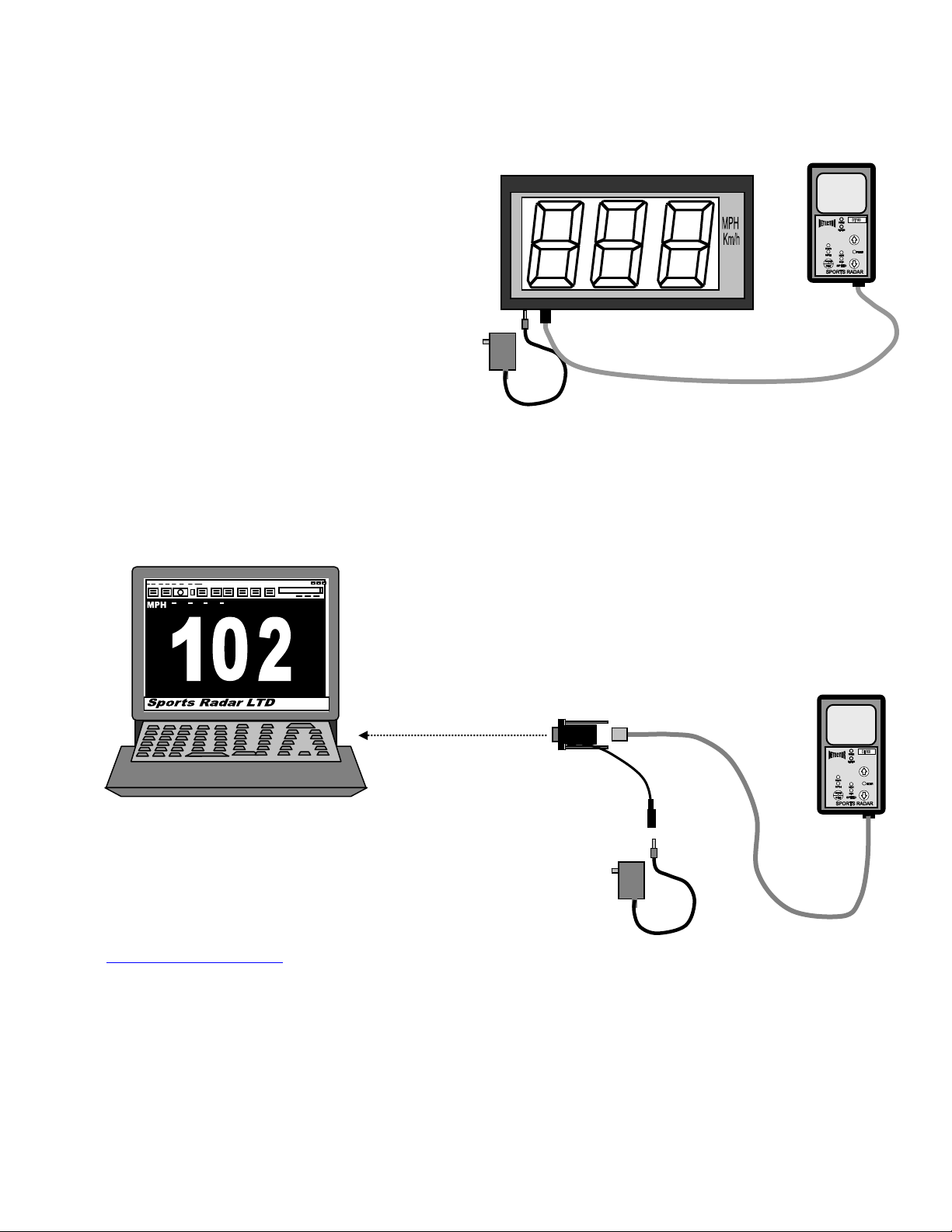
Connect the DT100 to a PC using a special adapter with power pigtail
and 9VDC power supply.
The adapter comes with a software CD that can display the speeds in
large screen digits, record and store speeds for individual players, date
and time stamp speeds, alarm on set speeds, and more.
Sports Radar’s WINDOWS based speed
acquisition and display program provides a large
readout of the speed, alarm on a user selectable
speed, individual player speed storage and
statistics and other features that can be tailored
to your specific application. Visit
www.sportsradargun.com for additional details.
Three digit LCD Displays
PC applications
9VDC power
supply DT100
DS400BL
PC serial port Adapter
with power plug
9VDC
Power
supply
Connects to an open
serial port (DB9) on a
WINDOWS based PC. DT100

Page 4 of 6
Power / Data cable for the DT100.
The DT100 has a permanently attached Power / Data cable with an RJ45 plug. This is a dedicated plug and should only
be connected to equipment using the proper adapter. DO NOT CONNECT THIS DIRECTLY TO A PC,other equipment or
network connection, damage to the Radar unit and / or the connected equipment can occur. The Data / Power cable
should be routed and secured at each 5 foot length so as to avoid stress on the cable.
Extender cables, in 25 and 50 foot lengths are available from Sports Radar.
Operating instructions
Once the installation is complete and the DT100 is connected to a display or PC and a power supply is attached, the
following will occur:
1. The display will count down from 999 to 000. Verify all digits are operating properly.
2. The POWER (Green) LED on the DT100 unit turns on, then after about 3 seconds all LED indicators blink on and
off and the READING (red) LED will turn on. The DT100 is now ready to take readings
Test the installation by striking the tuning fork, and holding it in front of the DT100. The connected display should blank
then show 65MPH.
There is a delay between readings of about 3 seconds and the RED LED will turn off during this delay when a reading is
recorded and then turn back on after this 3 second delay. When the READING LED is on, the DT100 is ready to take a
reading.
The DT100 is factory set for optimal performance in most applications, however there are features that allow the DT100 to
be customized for the specific application being used.
FILTER:
The FILTER is a method to increase the immunity to unwanted readings, and is useful to reduce unwanted readings from
adjacent court play, or troublesome noise sources near the radar unit. Increasing the FILTER (the up button) filters out
these unwanted readings. Decreasing the FILTER (the down button) gives the radar unit more range, or the ability to
register the speed of a target farther away, but also makes the radar unit more susceptible to undesired readings.
To increase or decrease the filter, press the UP or DOWN button (without first pressing the MODE/SET button), the red
FILTER indicator light turns on, and the filter can be adjusted up or down as required. When the desired filter number is
displayed, press the MODE/SET button.
The FILTER is factory set for typical installations; however, the specific installation may require some adjustments to the
FILTER number. The filter number should not be set less than 8 or more than 50.
SPEED storage: The DT100 stores up to 1000 speeds recorded in memory. These speeds can be downloaded to a PC
using the Sports radar acquisition and display program.
DT100
On the front of the radar unit there are three buttons MODE/SET,
UP arrow, and DOWN arrow.
MODE Function of the MODE/SET button:
1. MPH or Km/h selection: Pressing the MODE/SET button
changes the speed units, either MPH or Km/h. The speed
units are indicated by the indicator light above the units.
2. Minimum and Maximum speed limits: Press and hold
the MODE/SET button for about 3 seconds until the MIN
(red light) turns on. Then the minimum speed limit can be
adjusted up or down using the up and down buttons.
When the desired minimum speed is set, press
MODE/SET again, and the SET MAX (red light) turns on,
and you can set the maximum speed using the up and
down buttons. When the desired maximum speed limit is
set, press MODE/SET and the radar is ready to read, and
will only register speeds that are within the MIN and MAX
speed limits set.
Power on
indicator
Reading
indicator
Km/h indicator
MPH indicator
MODE/SET
button DOWN button
Set filter
indicator
UP button
Set maximum
speed indicator Set minimum
speed indicator
Radar face

Page 5 of 6
Resetting to FACTORY settings:
The Radar unit can be reset to initial factory settings by holding the MODE/SET button down when power is applied.
The factory settings are:
Minimum speed = 25MPH (40Km/h)
Maximum speed = 175MPH (282Km/h)
Filter = 8
MPH on
All stored speeds are cleared on factory set.
SECTION 3,
COSINE ERROR
The COSINE error affects all Doppler radar speed measuring devices. When the COSINE of the angle is zero, the
Doppler “sees” the target at 100% of its real speed. When the angle between two lines (defined below) is greater than
zero, the Doppler radar device “sees” the speed LESS than the actual target speed. Two lines make up the COSINE
angle (reference figure 3-1) and are defined as:
1. The line of the radar unit to target when it registers a speed
2. The line of target travel
For purposes of the effect on Doppler radar units this is called the COSINE angle. The COSINE factor, is a percentage of
the actual target speed and is based on the COSINE angle. The COSINE angle and the COSINE factor are not linear, that
is to say that if the angle changes by 10%, the factor will NOT change by 10%. Table 3-1 gives examples of COSINE
angles and factors.
In real applications, such as measuring the speed a baseball pitch into a net, there are an infinite number of angles during
the time the radar unit is measuring the speed (time taken when the ball is released and stops in the net). This is inherent
because the ball flight is never straight, it always has some “arc” to it. For practical purposes, this arc is minimal during the
time the speed is being calculated, and is beyond the scope of discussion. Another, somewhat insignificant fact is that
once the ball leaves the hand it is decelerating due to the friction of air, which is also ignored for this discussion.
For optimum accuracy to eliminate the COSINE error, if a line were drawn extending the line of flight of the ball and the
DT100 was positioned on this line (a collision course) the speed measurement would be accurate to the accuracy of the
processing device. Any position of the radar unit off this “collision course” makes a COSINE angle, and results in a
registered speed that is less than the actual target speed. The actual reduction in calculated speed based on the COSINE
angle is called the COSINE factor, examples of which are given in table 3-1.
TABLE 3-1, Cosine angles and factors
ANGLE COSINE Factor ANGLE COSINE Factor
0 deg 1.000 8 deg 0.990
2 deg 0.999 10 deg 0.985
4 deg 0.997 12 deg 0.978
6 deg 0.994 14 deg 0.970
In this case, the COSINE angle is about 10
degrees: The resulting COSINE error is 0.985
The registered speed would be 0.98 x actual ball
speed. So an actual ball speed of 100MPH would
register at 98MPH.
In a pitching booth, the COSINE factor can be a
useful tool to “maximize” a registered speed value
when the pitch is in the center of the receiving net
target, and if the pitch is off center, it will be
registered at a slower speed. This would make
“accuracy of the pitch” (hit the center of the net) an
important factor to realize the maximum displayed
speed.
8 feet
typical
Line of ball flight
Line between DT100
and point where
reading is registered
COSINE angle,
about 10 degrees

Page 6 of 6
TROUBLE SHOOTING:
1. Radar unit will not register a speed: First, reset the system by removing power from the display for 10 seconds,
then re-applying power.
a. On the radar unit, the POWER indicator (green LED) should be lit. If not, verify power is connected to the
display (the radar units get power from the Power/Data cable from the display) If the display is active
(counts down upon power up) then power is connected properly, at least to the display. If not, check the
outlet where the power supply is connected for proper 110VAC (standard household power). If the display
operates (counts down) then check that the cable connections and adapter (if used) are securely
connected. If the Green POWER LED is not lit, then there is most likely a connection problem with the
power data cable. If connecting to a PC, make sure the power supply is connected to the adapter, and is
plugged into to an operating outlet.
b. Verify the READING (Red LED) is on. If not on, make sure the MIN, MAX and FILTER indicator LED’s are
off. If any of these are on, press the MODE/SET button, until all these indicators are off and the MPH and
Km/H indicators toggle each time the MODE/SET is pressed. If the reading indicator does not turn on
after a few seconds, the Radar unit may be defective.
c. Verify the MIN and MAX speed limits are set within the speed you are reading. To check this, press and
hold the MODE/SET button until the MIN speed light comes on, the current minimum speed limit is shown
in the display. Press the MODE/SET button again, and the MAX speed limit is displayed. Press the
MODE/SET button again to exit the set speed limits mode.
d. Verify the operation with a tuning fork. If the POWER indicator, and the READING indicator are both on
(MIN and MAX and FILTER indicators are off) strike the tuning fork to make it ring, and hold it a few
inches in front of the unit. If the Reading indicator goes off, but the display still does not register a speed,
this indicates the radar unit is operating properly, and the problem may be in the cable, cable connection,
adapter, or possibly in the display. Check the connection pins on the cables for corrosion, clean or
replace as necessary. If no input configuration operates with multiple radar units, then the Display input(s)
may be defective, and will need factory service.
2. Radar works with a tuning fork, but will not read a pitch speed. If all items in 1 above are OK check the following:
a. Verify the FILTER setting is not too high. With the POWER and READING indicators on (and MIN and
MAX and FILTER indicators are off) Press the DOWN button, the FILTER indicator turns on, and the
display shows the filter number. Adjust this to 8 using the UP and DOWN buttons, then press MODE/SET
button. This low of a filter setting may give false readings, but it provides for maximum range. The
maximum range of the radar unit is typically 8 feet, so make sure the distance from the radar unit to the
net line is less than 6 feet.
b. If step a above allows the radar unit to read the ball speed, it is recommended that the filter number be
increased to the point where it will not read the speed (MAX number, then adjusted back down, ½ way
between 8 and the MAX number.
c. If step a above makes the radar unit continuously false read, press the UP button, then the MODE/SET
button, repeating this until the false readings stop. Verify the radar unit reads the intended target (pitch a
ball). If the speed cannot be registered, then there is a noise source too close to the radar unit. The noise
source must be shielded or moved, or the radar unit must be positioned CLOSER to the net.
CALIBRATION: The radar units are factory calibrated when shipped, and are assured within specifications for 1 year
of ship date. If the facility requires radar units to be calibrated at specific intervals for competitive events, Sports Radar
offers a calibration service: The DT100 can be returned for calibration for $75 each plus shipping costs.
One Year Warranty
This product is warranted to be free of manufacturing defects for a 1-year period from the original consumer date of purchase. The
warranty does not include damage to the product resulting from accident, misuse, improper installation, operation, or unauthorized repair
or alteration. Opening the product case will void this warranty. If the product should become defective within the warranty period, Sports
Radar Ltd., will repair or replace it at our option, free of charge. You must fill out and return the enclosed registration form to ensure
warranty coverage failure to fill out registration form may void warranty. To obtain warranty service, first contact Sports Radar’s warranty
repair department 352-563-5298, then upon approval, send the unit at purchaser's cost to:
Sports Radar, Ltd., 9119 W. Veterans Dr., Homosassa, FL 34448
Return shipping to purchaser will be at Sports Radar Ltd.’s cost inside the 48 continental United States, international shipping is the sole
responsibility of the purchaser.
The consumer's sole remedy shall be such repair or replacement as is expressly provided above, and we shall in no event be liable for
any incidental or consequential damages arising out of the use or inability to use this product for any purpose whatsoever. Some states
do not allow the exclusion or limitation of incidental or consequential damages, so the above limitation or exclusion may not apply to
you. This warranty gives you specific rights. You may also have other rights, which vary, from state to state. Manufactured by Sports
Radar, Ltd. in the U.S.A.
Table of contents
Popular Security Sensor manuals by other brands

C.P. Electronics
C.P. Electronics MWS1A-IP installation guide

LEGRAND
LEGRAND 675 29 quick start guide

Air Specialties Express
Air Specialties Express LU-BELT Installation, operating and maintenance instructions

SECUMAR
SECUMAR SECULUX CFX-II FITTING INSTRUCTION

Bosch
Bosch Blue Line D1-P quick start guide

LEGRAND
LEGRAND 695 93 manual

Argus Security
Argus Security Taurus TW-DM-01 manual

Honeywell
Honeywell FS19X Series Installation guide and operating manual

Lena Lighting
Lena Lighting WSED414 HIM14 manual

Danatronics
Danatronics ECHO FD quick start guide

BEA
BEA WIZARD II SMR user guide

Carrier
Carrier Graviner Mk6 Installation, operation and maintenance manual


