4
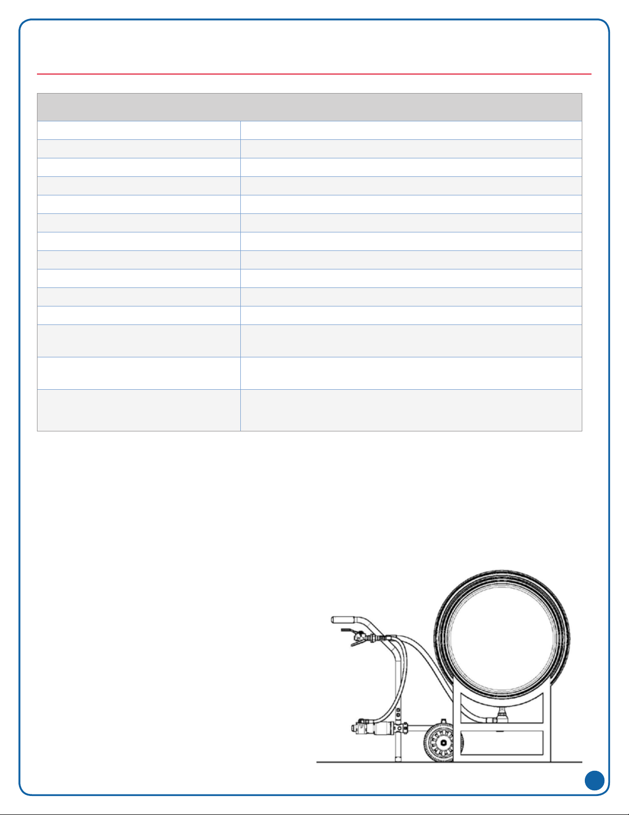
TJM60AGTankCleanerǀ08/07/2017
READ AND FOLLOW INSTRUCTIONS:
WARNING: All safety related and operating instructions
should be read before the nozzle is operated. Follow all
operating instructions. Failure to do so could result in
serious injury.
• WARNING: It is important to recognize proper
safety precautions when using a pressurized spray
system. Fluids under pressure can penetrate skin
and cause severe injury.
• WARNING: When dealing with pressure
applications, the system pressure should never
exceed the lowest rated component. Always
know your system and all component capabilities,
maximum pressures and ow rates.
• WARNING: Before performing any maintenance,
make sure all liquid supply lines to the machine
are shut off and/or disconnected and chemical/
uid are drained.
• WARNING: The use of any chemicals requires
careful control of all worker hygiene.
• WARNING: Spraying Systems Co. does not
manufacture or supply any of the chemical
components used in this equipment and is not
responsible for their effects. Because of the large
number of chemicals that could be used and their
different chemical reactions, the buyer and user
of this equipment should determine compatibility
of the materials used and any of the potential
hazards involved.
• WARNING: Before use be sure appropriate
connections are secure.
• WARNING: Spraying Systems Co. strongly
recommends the use of appropriate safety
equipment when working with potentially
hazardous chemicals.
This equipment includes but is not limited to:
• Safety shoes
• Safety glasses or face shield
• Chemical and heat-resistant gloves
• Long sleeve shirt and long pants
NOTE: Always remember to carefully read the chemical
manufacturer’s label and follow all directions.
• WARNING: DO NOT USE TO SPRAY FLAMMABLE
LIQUIDS--SUCH USE COULD RESULT IN FIRE
OR EXPLOSION CAUSING BODILY INJURY OR
DEATH.
• WARNING: Never operate tank cleaning machine
in the open due to the potential of bodily injury.
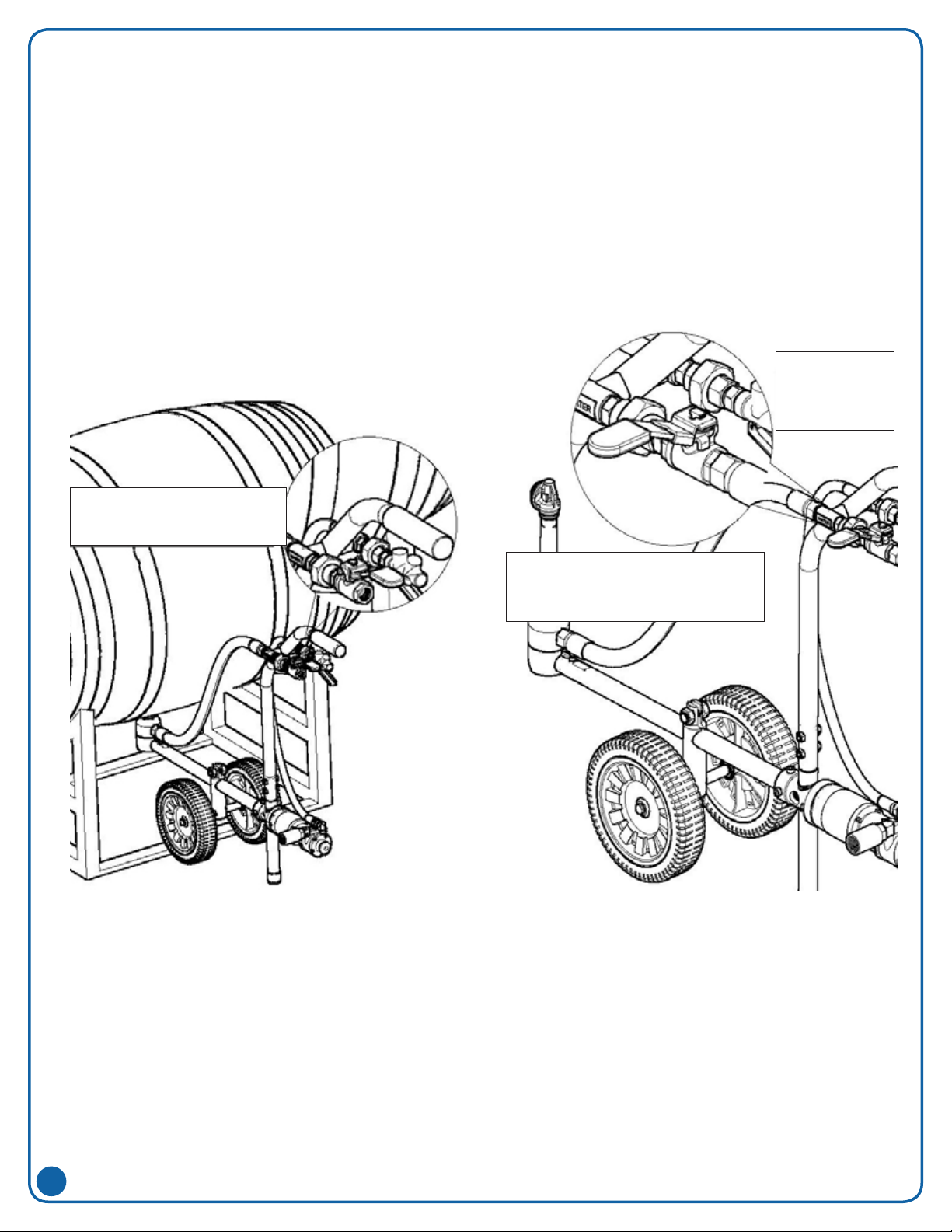
• WARNING! Never operate barrel washer with
nozzle head outside of tank. Make sure ball valve
is in off position for water line whenever nozzle
head of tank washer is outside of tank.
• WARNING: It is important to operate equipment
within the temperature range of all components.
Also insure that appropriate time lapses or
proper safety equipment is used when handling
components after they’re exposed to high
temperatures.
• WARNING: Removed equipment from the tank
before attempting any repairs.
• WARNING: Do not put any part of your body in the
tank during operation of the tank cleaner. This is
NOT a safe procedure for verication of operation.
• WARNING: To insure the safety of the equipment
as well the individuals using them, only use
Spraying Systems Co. components.
• WARNING: When packaging and transporting use
structurally sound boxes or crates that can handle
the weight of the equipment.
• WARNING: Tank cleaners should be ushed out
with clean water before they’re stored or shipped
to minimize health hazards or cross contamination.
• WARNING: Do not use any equipment outside
the intended purposes of the product. Misuse can
result in personal injury or product damage.
GENERAL SAFETY INSTRUCTIONS
-