4spray.com | 1.800.95.SPRAY | Intl. Tel: 1.630.665.5000
INTRODUCTION
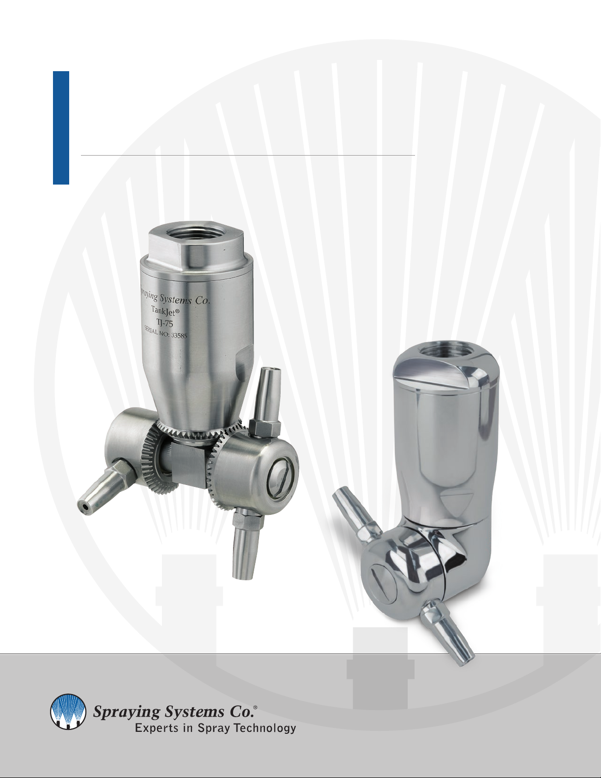
The TankJet®75 and 75H models are hydraulically driven rotating
heads with nozzles ejecting streams of liquid for spanning internal
tank surfaces to be cleaned, sanitized, treated, or rinsed. The
TankJet 75H-2 or 75H-4 models feature an enclosed gear housing
for hygienic option. Either model will provide a complete 360°
indexing path in both planes, the index pattern will repeat every
45 revolutions. The TankJet 75-2 and the 75H-2 are specifically
designed for 3" dia. openings, care must be exercised during
insertion and retraction of this unit because of the nozzle swing
span. The TankJet 75-4 and 75H-4 incorporates 2 nozzle hubs
thus 4 nozzles, and is designed for 4.2" dia. openings. The units
may be installed on a permanent basis (C.I.P.). Many types of
fluids, sanitizers, detergents and caustics may be used through
this unit to assist it’s cleaning effectiveness. (Please note caution
below.) The cleaning effectiveness of any unit is proportional to
all the applicable variables, such as volume, pressure, chemicals,
impingement, drainage, soils, etc. The unit will only operate
properly when mounted in the vertical position (suspended or
inverted) and can clean almost any type of contained area within
its range.
Caution: If chemicals, hazardous materials, operations, and
equipment are used in conjunction with this cleaning equipment,
it is the responsibility of the user to establish appropriate
associated safety and health practices. Prior to application, the
user must consult and determine the applicability of regulatory
(federal, state, local and facility) safety and environmental
agency limitations.
SPECIFICATIONS
TANKJET 75-2 OR -4 HUB MODELS:
SSCO. PART # DESCRIPTION
TJ75*-2-234 Standard Nozzle: 0.234
PSI: 150-300 | GPM: 17-24 | NPT
TJ75*-2-234LP Low Pressure Nozzle: 0.234
PSI: 75-150 | GPM: 12-17 | NPT
TJ75*-4-125 Standard Nozzle: 0.125
PSI: 150-300 | GPM: 15-21 | NPT
TJ75*-4-172 Standard Nozzle: 0.172
PSI: 150-300 | GPM: 23-33 | NPT
TJ75*-4-172LP Low Pressure Nozzle: 0.172
PSI: 75-150 | GPM: 15-23 | NPT
* Add B for BSPT connections after the model no.
Add SF for sanitary tri-clover flange after the model no.
See Tank Cleaning Catalog 75TJ for further flow and performance information.
TANKJET 75H-2 OR -4 HUB MODELS:
SSCO. PART # DESCRIPTION
TJ75H*-2-234 Standard Nozzle: 0.234
PSI: 150-300 | GPM: 17-24 | NPT
TJ75H*-2-234LP Low Pressure Nozzle: 0.234
PSI: 75-150 | GPM: 12-17 | NPT
TJ75H*-4-125 Standard Nozzle: 0.125
PSI: 150-300 | GPM: 15-21 | NPT
TJ75H*-4-172 Standard Nozzle: 0.172
PSI: 150-300 | GPM: 23-33 | NPT
TJ75H*-4-172LP Standard Nozzle: 0.172
PSI: 75 -150 | GPM: 15-23 | NPT
* Add B for BSPT connections after the model no.
Add SF for sanitary tri-clover flange after the model no.
See Tank Cleaning Catalog 75TJ for further flow and performance information.
MATERIALS
• 316 Stainless Steel (UNS S31600)
• PTFE
• UHMW-PE
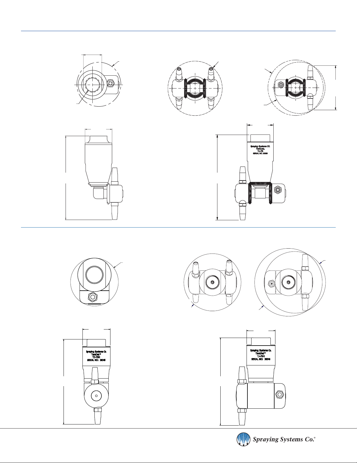
CONSTRUCTION
Referring to the Parts List on page 7 and 8, the unit comprises two
basic components; the drive, consisting of the body, motor, rotor,
and shaft; and the nozzle head, consisting of the nozzle body,
bushings, nozzles, and elbow shaft.
PRINCIPLE OF ROTATION
The liquid enters the inlet cap (1) and then flows through the
oblique and bypass holes in the motor (2) causing a swirling
motion in the liquid. This swirling liquid goes down the outside of
the vertical shaft (5) past the 6 tooth rotor (3) imparting rotation
to the rotor and thus the vertical shaft. The liquid flows through
the elbow shaft into the nozzle body (7), to be distributed out
each off-set nozzle (12). The rotational speed of these units can
be regulated through the use of various motor bypass plugs,
which influences the fluid diversion to provide additional speed.
Reference the Troubleshooting section and the Drawing Parts
List for additional information and location.
CLEANING DIAMETER
The cleaning and wetting distances are a function of rotational
speed and liquid pressure applied. The TankJet 75 has an
effective cleaning diameter of 30 ft. (9.1 m).