SprayTECH 1150 User manual

Diaphragm Pumps
1150
Piston Pumps
EP2105
EP2205
EP2300
EP2300se
EP2400
EP2510
GP2605
GP2905
HVLP
CS5100
CS8100
CS9100
Maxum II Gun
Diaphragm Pumps
1150
Piston Pumps
EP2105
EP2205
EP2300
EP2300se
EP2400
EP2510
GP2605
GP2905
HVLP
CS5100
CS8100
CS9100
Maxum II Gun


1
Owner's Manual
ED1150 Airless Sprayer
Model no. 0294059
Form no. 0294968C
© 1996 Wagner SprayTech. All rights reserved.
Plus

2
THIS UNIT IS PROVIDED WITH A THERMALLY PROTECTED AUTOMATIC RESET. IF AN OVERLOAD
OCCURSTHETHERMALLY PROTECTED AUTOMATICRESETDISCONNECTS THE MOTOR FROMTHE
POWER SUPPLY.
• Motor will restart without warning when protector automatically resets.
• Always disconnect motor from power supply before working on equipment.
• Whenthermally protected automatic reset disconnects the motor from thepowersupply,relieve pressure by
turning priming valve to “prime” .
• Turn ON-OFF switch to OFF.
CAUTION: THE CAUSE OF THE OVERLOAD SHOULD BE CORRECTED BEFORE RESTARTING.
CAUTION
CAUTION
Be sure to read, understand and observe all safety
precautions and warnings. See pages 3 thru 6.
Read product labels—follow manufacturer’s recommendations
All procedures and recommendations presented in this manual are based on information which SprayTECH believes
to be reliable. However, such procedures and recommendations are to be implemented and used by persons reading this
manual at their own discretion and risk.
Label directions, procedures and precautions set forth by the manufacturers of finishing products are to be considered
the best source of information on those products. No attempt has been made in this manual to provide complete data on
all the various materials which may be used in your airless sprayer.
Application procedures are presented here as suggestions only, and are not to be construed as representations or
warranties as to safety, performance, results or fitness for any intended use ot the various types of products mentioned.
© 1995 WAGNER SPRAY TECH CORPORATION. ALL RIGHTS RESERVED.
BEFOREYOU CALL
Have the following information available:
Model #____________
Serial #____________
Purchase Date________________________

3
SAFETY PRECAUTIONS
This manual contains information which must be read and understood before using the equipment. When you come to an
area which has one of the following symbols, pay particular attention and make certain to heed the safeguard.
WARNING
Important safety information indicates a hazard which may cause serious injury or loss of life.
CAUTION
Important information that tells how to prevent damage to equipment or how to avoid causes of minor injuries.
Note: Gives important information which should be given special attention.
IMPORTANT
EXTENSION CORD SELECTION
If an extension cord is used, make sure it is of the three-conductor type with NEMA connectors so a continuous grounding circuit is
provided from tool to power circuit receptacle. Also, be sure that the conductor size is large enough to prevent excessive voltage drop
which will cause loss of power. A table of recommended extension cord sizes will be found below.
For nameplate ampere ratings which are between those given, use the extension cord recommended for the NEXT HIGHER ampere
rating.
If an extension cord is to be used outdoors it must be marked with the suffix W-A following the cord type designation. For example —
SJTW-A to indicate it is acceptable for outdoor use.
RECOMMENDED EXTENSION CORD SIZES FROM SERVICE ENTRANCE TO PUMP MOTOR.
NAMEPLATE AMPERE RATING
Cord
Lgth. 0 to 5 6 7 8 9 10 11 12 13 14 15 16 17 18 19 20
25Ft. 18 18 18 18 18 18 16 16 16 14 14 14 14 14 12 12
50Ft. 18 18 18 18 18 18 16 16 16 14 14 14 14 14 12 12I
25Ft. 18 18 18 18 18 18 16 16 16 14 14 14 14 14 12 12
100Ft. 18 18 18 16 16 16 16 16 14 14 14 14 14 14 12 12
125Ft. 18 18 16 16 16 14 14 14 14 14 14 12 12 12 12 12
150Ft. 18 16 16 16 14 14 14 14 14 12 12 12 12 12 12 12

4
WARNING
PREVENTION
HAZARD
•
• Painthosecandevelopleaksfromwear,kinking,abuse,
etc. A leak is capable of injecting material into the skin.
The paint hose should be inspected before each use.
• NEVER use a spray gun which does not have a trigger
lock or trigger guard in place and in working order.
• All accessories must be rated at or above 3000 P.S.I.
(Includes spray tips, guns, extensions, and hose).
• In case of skin injection see physician immediately.
Injection Injury - A high pressure stream of paint pro-
duced by this equipment can pierce the skin and
underlying tissues, leading to serious injury and pos-
sible amputation.
DONOTTREATASASIMPLECUT! Injection-
can lead to amputation. See a physician im-
mediately.
NOTE TO PHYSICIAN: Injection into the skin
isatraumaticinjury.Itisimportanttotreatthe
injury surgically as soon as possible. DO
NOT delay treatment to research toxicity.
Toxicity is a concern with some coatings
injected directly into the blood stream. Con-
sultation with a plastic surgeon or recon-
structive hand surgeon may be advisable.
• Maximum operating range of the gun - 3000 PSI fluid
pressure.
•NEVER aim the gun at any part of the body.
•NEVER allow any part of the body to come in contact
with the fluid stream. DO NOT come in contact with a
fluid stream created by a leak in the fluid hose.
•NEVER put hand in front of the gun. Gloves will not
provide protection against an injection injury.
• ALWAYS lock the gun trigger, shut fluid pump off and
releaseallpressurebefore servicing,cleaningtipguard,
changing tips, or leaving unattended. Simply turning off
the electrical power will not release pressure in the
system. The Prime Spray Valve must be turned to the
position to relieve the pressure.
•ALWAYShavethetipguardinplacewhilespraying.The
tip guard provides some protection against injection
injuries but is mainly a warning device.
ALWAYS remove spray tip before flushing or cleaning
the system.

5
WARNING
HAZARD PREVENTION
Explosionorfire-Solventandpaintfumescanexplodeor
ignite causing property damage and/or severe injury. • Exhaust and fresh air introduction must be provided to
keeptheairwithinthesprayareafreefromaccumulation
of flammable vapors.
• Avoidallignitionsourcessuchasstaticelectricitysparks
open flames such as pilot lights, hot objects such as
cigarettes,and sparksfromconnecting anddisconnect-
ing power cords and working light switches.
• Fire extinguishing equipment must be present and in
working order.
• Keep the pump away from spray area to avoid solvent
andpaintfumes. The pumpcontains arcingparts which
emit sparks.
• High velocity flow of material through equipment may
develop static electricity. The equipment being used,
and objects in and around the spray area, must be
properlygroundedtopreventstaticdischargeandsparks.
• Use only conductive or grounded high pressure fluid
hoses for airless applications. Be sure that gun is
grounded through hose connections.
• Power cord must be connected to a grounded circuit.
• Follow the material and solvent manufacturer's safety
precautions and warnings.
• WHEN FLUSHING EQUIPMENT use lowest possible
pressure.

6
WARNING
PREVENTION
HAZARD
Explosion hazard incompatible materials - May cause
property damage or severe injury.
General - May cause property damage or severe injury.
Hazardous vapors - Paints, solvents, insecticides, and
other materials may be harmful if inhaled causing se-
vere nausea, fainting, or poisoning.
• Read all instructions and safety precautions before
operating.
• Comply with all appropriate local, state and national
codes governing ventilation, fire prevention and
operation.
• The United States Government Safety Standards have
been adopted under Occupational Safety and Health
Act. These standards, particularly the General Stan-
dards, Part 1910 and construction Standard, Part 1926,
should be consulted.
• This high pressure airless pump is designed to be used
with authorized SprayTECH parts only. When using this
pump with parts that do not comply with the minimum
specifications and safety devices of the pump manufac-
turer, the user assumes all risks and liabilities.
• Before each use, check all hoses for cuts, leaks, abra-
sion or bulging of cover or damage or movement of
couplings. If any of these conditions exist, replace the
hose immediately. Never repair a paint hose. Replace it
with another grounded hose.
• Allhoses,swivels,guns,andaccessories used withthis
unit must be pressure rated at or above 3000 PSI.
• Usearespiratorormaskwheneverthereisachancethat
vapors may be inhaled. Read all instructions with the
masktoinsurethatitwillprovidethenecessaryprotection
against the inhalation of harmful vapors.
• Halogenated hydrocarbon solvents such as methylene
chloride and 1,1,1 - Trichlorethane are not compatible
withaluminumandmaycauseanexplosion.Ifunsure of
a material’s compatibility with aluminum, contact your
coatings supplier.
• Some spray guns and accessories cannot be used with
halogenated hydrocarbon solvents. Be certain of com-
patibility before use with halogenated hydrocarbon sol-
vents.
• The SprayTECH ED1150 pump is not compatible for
use with halogenated hydrocarbon solvents. The
SprayTECH G-05, G-09, and G-10 guns must NOT be
used with halogenated hydrocarbon solvents.

7
GENERAL DESCRIPTION
Be sure to read the IMPORTANT SAFETY INFORMA-
TION on pages 3 thru 6 before using this sprayer.
Your SprayTECH sprayer is a powerful, easy to operate
and easy to service machine. Since it operates on the
airless principle, no air compressor is needed.
Power is supplied by a 3/4 horsepower, TEFC electric
motor. The flow rate is 0 to .50 gallons a minute. The
pressure is adjustable from 0 to 3000 pounds per square
inch.
COMPONENT FUNCTIONS
See Figure 1 for component locations.
Power for the sprayer is supplied by a 3/4 horsepower,
TEFC electric motor (see Figure 1). It is located at the rear
ofthesprayerandisconnectedtothehydraulicpump.The
motorisfurnishedwitha3-wireelectriccord.Thethirdwire
(ground)shouldneverbecutoff.Anyextensioncordsused
Figure 1.-Sprayer Component Locations
must also be 3-wire and 3-wire plug that will plug into a 3-
wiregroundedelectricaloutlet.Donotuse2-wireextension
cords. Shorter extension cords will assure maximum
electricalpowerforproperoperation,usemorepaint hose,
not more extension cords. Refer to page 3 for extension
cord selection.
Cords and extension cords should be protected from
vehicletrafficandsharpcuttingedgesorobjects.Anyworn
or damaged cords should be replaced promptly.
The motor has an automatic overload protective switch.
This switch disconnects the motor from electrical supply if
overload occurs. The motor can be started again after 5
minutes. The cause of the overload should be corrected
before restarting.
Themotor should always be kept clean anddry. Paint acts
asaninsulator.Therefore,toomuchpainton themotor will
cause it to overheat.
ON-OFF SWITCH
The ON-OFF switch is located on the side of the electric
motor (see Figure 1).
©1995 WAGNER SPRAY TECH CORPORATION. ALL RIGHTS RESERVED.
Hook
Suction Set
Hydraulic Pump
Pressure
Control
Knob
Paint
Pump
Inlet
Valve
Priming
Knob
On/Off Switch
Motor
Outlet
Valve

8
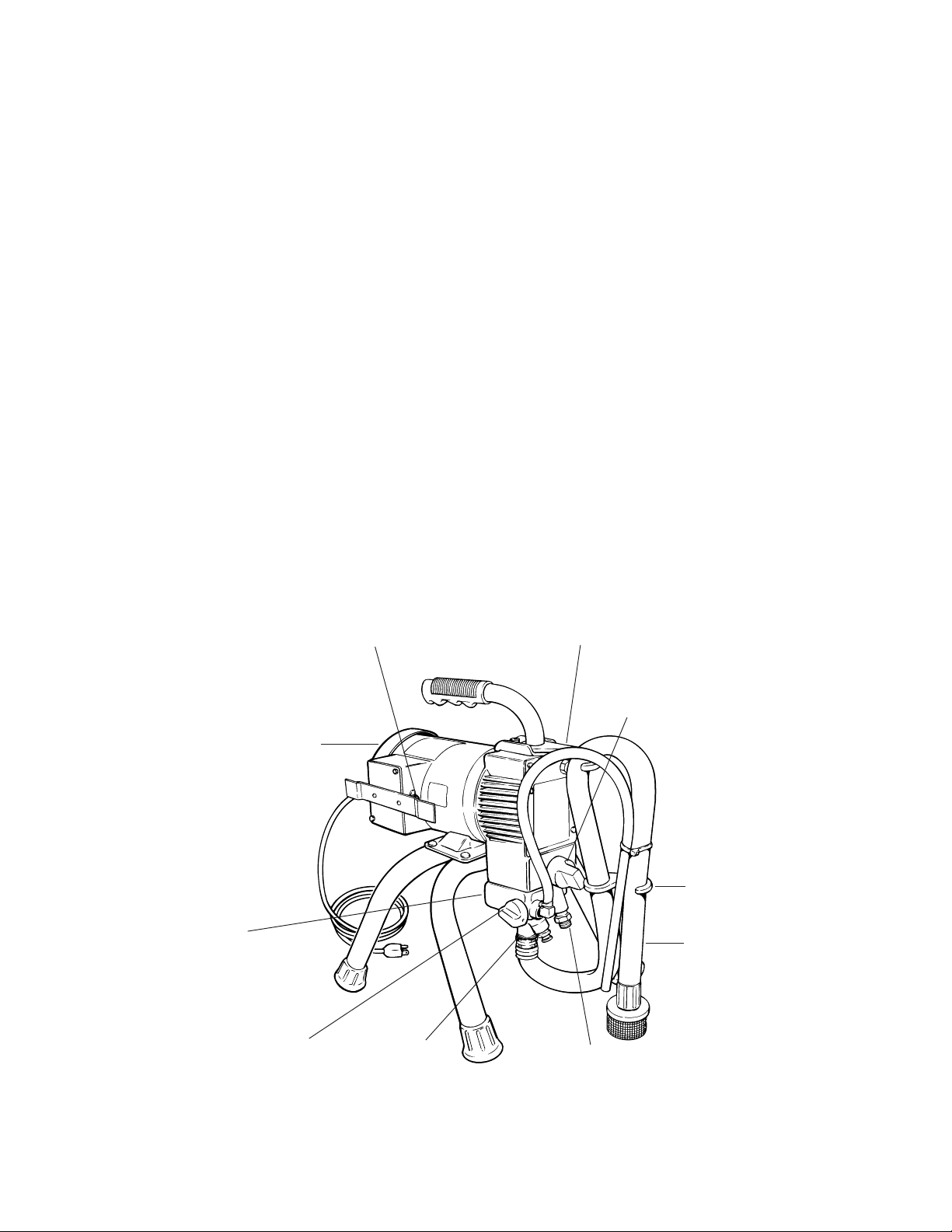
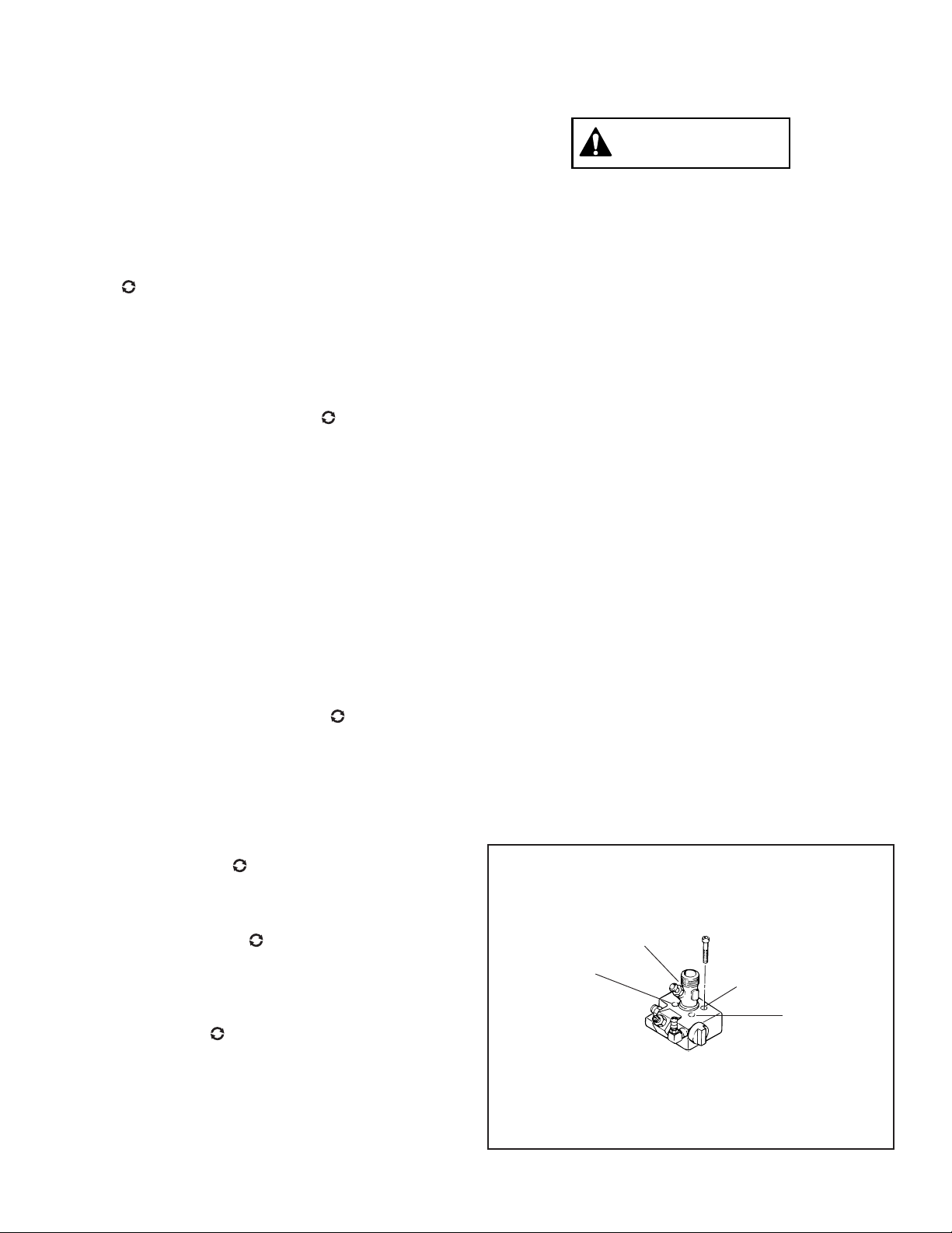
The paint pump is located below the hydraulic pump (see
Figure 1). The two pumps are bolted together by four
socket head capscrews. The diaphragm separates the
pumps. The paint pump operates as follows: The piston in
the hydraulic pump forces hydraulic oil toward and away
from the diaphragm. This action moves the diaphragm up
and down. Diaphragm movement forces paint through the
spray gun at high pressure.
DIAPHRAGM
The diaphragm is the heart of the sprayer. In addition to
pumping paint, it also serves as a gasket between the
hydraulic pump and paint pump. As such, it prevents the
paint and oil from mixing. The sprayer operates at 1725
strokes per minute. This means that the diaphragm forces
a “gulp” of paint out of the spray gun 1725 times every
minute.
An insert fits in the inlet hole on the underside of the paint
pump. This insert reduces wear by protecting the dia-
phragm from the metal edges of the inlet hole.
The diaphragm is made of flexible, tough plastic. It is not
harmed by common solvents.
NOTE
The diaphragm should be replaced whenever the paint
pumpis removed. Using the old diaphragm willresult in
limited diaphragm life and fluid leaks.
For the hydraulic pump location, see Figure 1. It operates
asfollows: The electric motor is connectedtotheeccentric
bearing, which is inside the hydraulic pump. The piston
restson the bearing. The movement ofthebearingcauses
the piston to move up and down. When the trigger on the
gunispulled back,thisactionmovesthe pumpdiaphragm.
Diaphragm movement forces the paint through the outlet
valveandoutthepainthoseandspraygun.Thepaintgoes
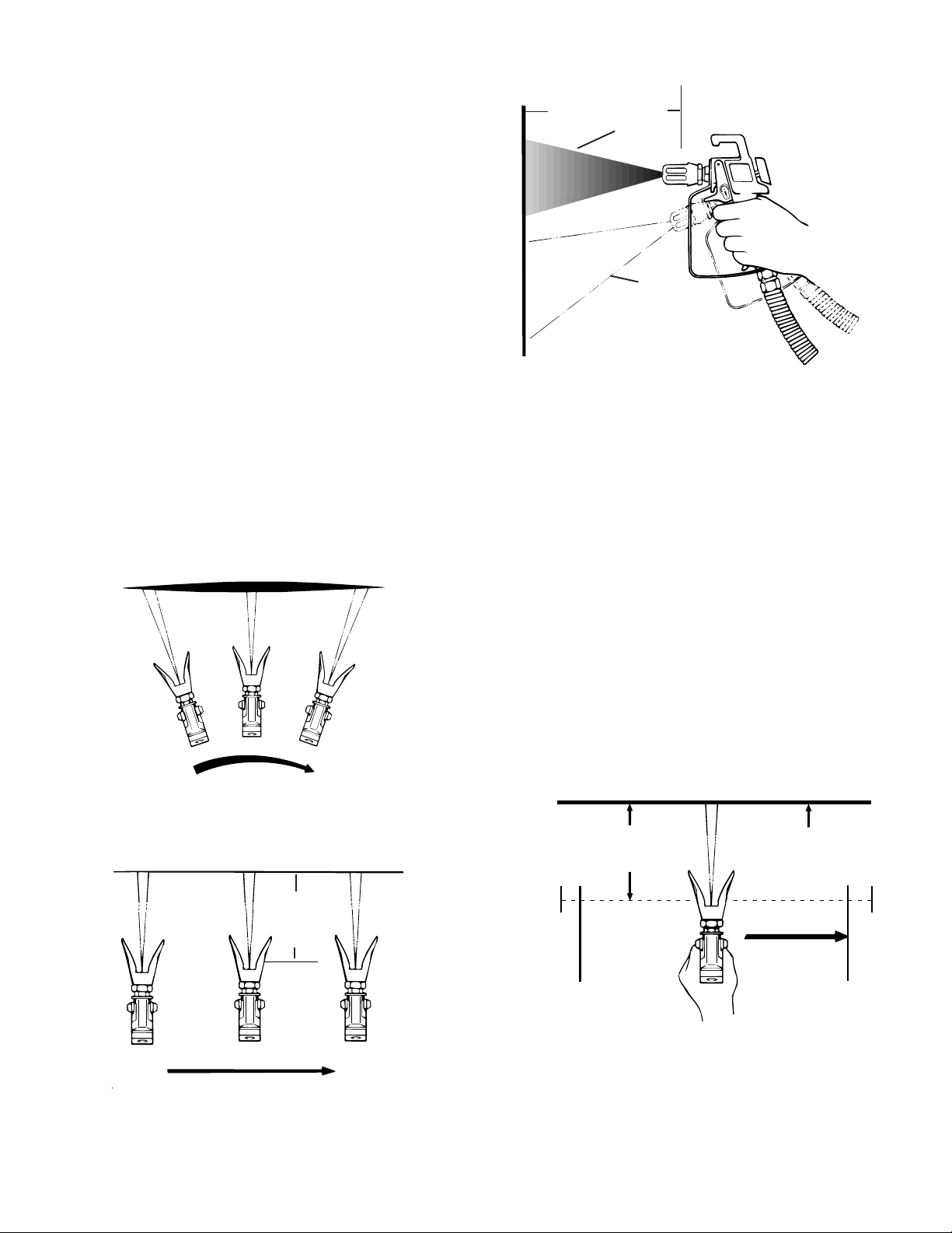
throughthespraygunathighpressure,causingittobreak-
up (atomize) into fine particles. This gives a smooth and
even paint coating. Pressure and delivery rate are regu-
lated by the pressure control knob and spray tip size.
PRESSURE CONTROL KNOB
The pressure control knob controls the pressure control
valve.Itismanuallyoperated.Itislocatedonthefrontofthe
hydraulic pump near the bottom of the sprayer (see Figure
1). When the knob is turned cIockwise, more hydraulic
pressureisdirectedtowardthediaphragm.Whentheknob
is turned counterclockwise, less hydraulic pressure is
directed toward the diaphragm. The pressure control knob
regulates the pressure on the diaphragm from 0 PSI when
turned fully counterclockwise to 3000 PSI when turned
fully clockwise.
HYDRAULIC PUMP PAINT PUMP
INLET VALVE
Theinletvalveislocatedonbottomofthepaintpumpatthe
front of the sprayer (see Figure 1). The suction nut end of
thesuctiontubescrewsontothisvalve.Thevalveoperates
automatically. It controls the flow of paint from the paint
container into the paint pump. It does this by opening up
when the piston and diaphragm are on the downstroke,
allowing a “gulp” of paint to enter the paint pump. The inlet
valve then closes when the piston and diaphragm are on
the upstroke. This closing prevents paint from going back
through the inlet valve into the paint container (inlet valve
actsasacheckvalve).Instead,thepaintisdirectedoutthe
spray hose and spray gun by the outlet valve.
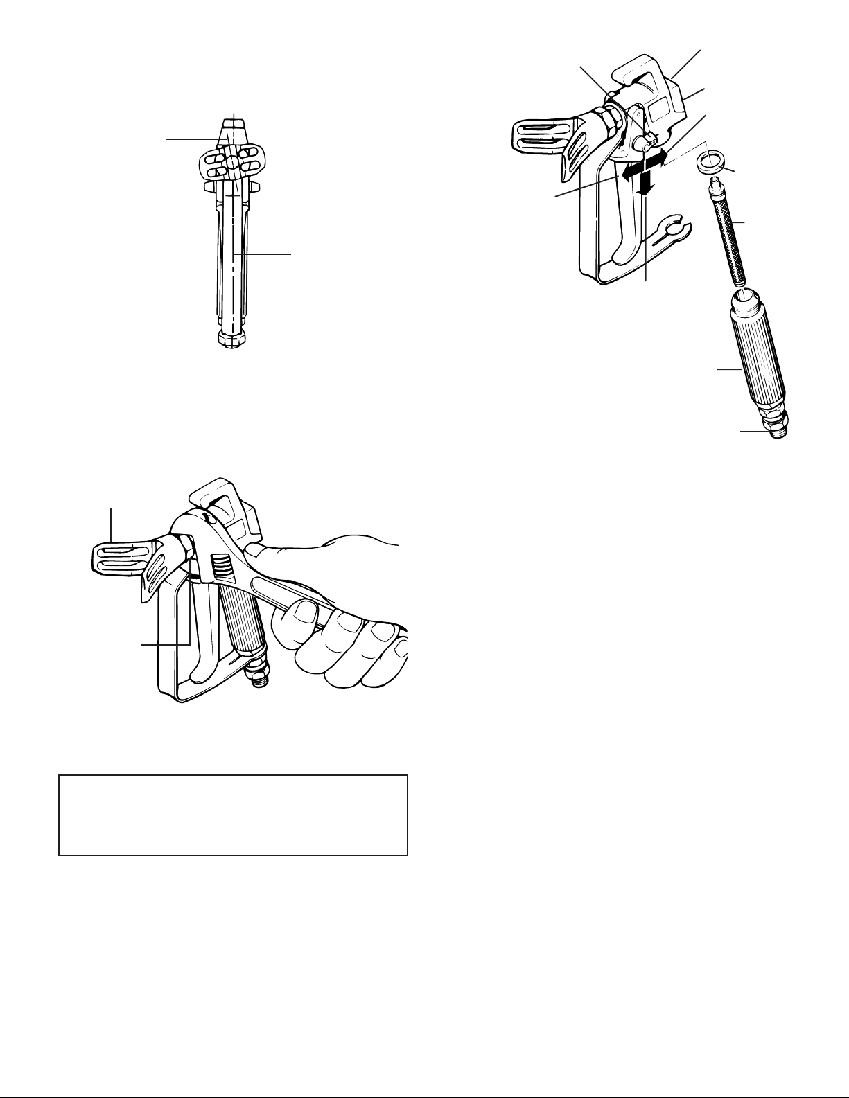
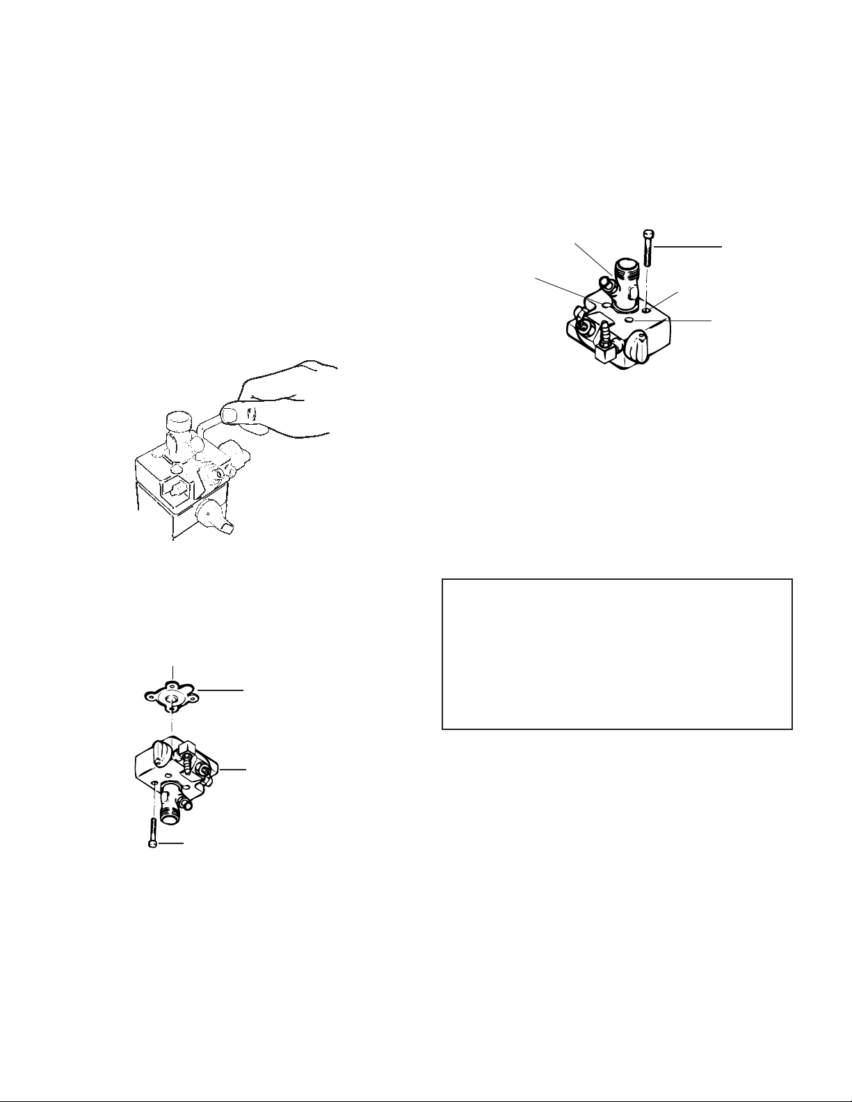
The inlet valve is a one-piece configuration. It contains a
device to dislodge a stuck valve by simply pushing the
plunger button on the side of the valve body.
NOTE
DO NOT START PUMP UNDER PRESSURE. RE-
DUCEPRESSURE TO ZERO BY TURNINGPRIMING
KNOBTOPRIMEPOSITION . FAILURETODOSO
WILL DECREASE MOTOR LIFE.
CAUTION
The plunger button should never be pushed during
operation as this may cause premature failure of the
inlet valve.
OUTLET VALVE
Theoutletvalveisalsolocatedonbottomofthepaintpump
at the front of the sprayer (see Figure 1). It operates
automatically, serving as a check valve. When the priming
valveison (spray)position,theoutletvalvedirectsthe
flowof paintoutinto thesprayhose andintothe spraygun.
When the diaphragm and piston act to “gulp” more paint,
theoutletvalvecloses.Theclosedvalveprevents(checks)
paint in the spray hose and spray gun from returning to the
paint pump.

9
tainer.Whentheprimingknobisturnedto (prime),paint
is drawn up the suction tube into the paint pump. The paint
pump then routes the paint through the return tube back to
thepaintcontainer.Thisprimesthepaintingsystem.When
the priming knob is turned to (spray), flow is shut off
through the return tube and the sprayer can spray.
Theoutletvalvealso contains a device to dislodge a stuck
valve. Simply push the plunger button located on the side
of the paint block before starting the pump.
You can see that the inlet valve and outlet valve work in
harmony with the diaphragm and piston. As a" team" they
pump paint.
CAUTION
The plunger button should never be pushed during
operation as this may cause premature failure of the
outlet valve.
PRIMING KNOB
Theprimingknobcontrolstheprimingvalve.Itislocatedon
the right front of the paint pump at the front of the sprayer
(see Figure 1). It can be manually turned to the or
position. When on (prime) it serves to rid the sprayer of
air by directing the initial air volume of the inlet valve back
into the paint container. It will continue to do this until paint
comes through and it is manually switched to the
(spray)position.Itthendirectsthepaintouttheoutletfitting
to the spray hose and on to the spray gun.
The priming valve also serves to relieve pressure on the
system during shutdown and cleanup. The pressure is
relieved by turning the priming knob to .
CAUTION
CHANGE THE POSTION OF THE PRIMING KNOB
SLOWLY. THISWILLPREVENTBREAKINGANYVALVE
PARTS. ALWAYS REDUCE THE PRESSURE WITH
THE PRESSURE CONTROL KNOB BEFORE TURNING
THE PRIMING KNOB.
SUCTION SET
The complete suction set consists of (1) the suction tube
with a suction filter on one end and (2) the return tube (see
Figure1).Bothsuctionandreturntubearechemicalandoil
resistant. One end of the suction tube and one end of the
return tube screw onto the paint pump (see Figure 1).
These two fittings need to be tight enough to keep air from
being drawn in. The other two ends go in the paint con-
WARNING
DO NOT IMMERSE THE PAINT HOSE IN ANY
SOLVENTS.
The paint hose and the electric cord should always be
protected from vehicle traffic and sharp cutting edges
or objects. If the paint hose is cut, worn, or damaged it
mustbereplacedwithanotherhighpressuregrounded
hose.
The paint hose can develop leaks from wear, kinking,
abuse,etc.Aleakiscapableofinjectingspraymaterial
into the skin. Therefore, the paint hose should be
inspected periodically. Never repair a paint hose —
replace it with another high pressure grounded hose.
NOTE:
DO NOT USE THE SPRAYER UNLESS
THE SUCTION FILTER IS IN PLACE!
HIGH PRESSURE OUTLET FITTING
The high pressure outlet fitting is located on the front side
of the paint pump (see Figure 1). The paint hose is con-
nectedtoit.Theoutletfittingconnectionsmustbeverytight.
Otherwise, fluid will leak out the connections when pres-
sure builds up in the system.
PAINT HOSE
The high pressure paint hose (see Figure 1) has perma-
nently swaged fittings. It is grounded with a static conduc-
tor. This conductor serves to “drain off” any static charge,
preventing shock. The conductor is sandwiched between
twoinsulating sheathswhichresist breakingandabrasion.

10
ASSEMBLY OF A NEW
SPRAYER
1. Screw the return fitting into the elbow on the front side
ofthepaintpump.Bothfittingsshouldbehandtightonly,
but tight enough to prevent air from being drawn in.
2. Screwthepainthose,wrenchtight,ontotheoutletfitting
on the front side of the paint pump.
SPRAY GUNTIP SELECTION
Select a spray gun tip as follows:
LACQUERS &
STAINS ENAMELS LATEX
0153315 0153317 0153319
0153415 0153417 0153419
Example 0153 3 19
0153 3 19
Prefix Spray Pattern Size of Spray Tip
Width In Degrees Holes In Inches
(In this case, 30°) (In this case,.019")
Figure 3.-Spray Tip Assembly Sequence.
Spray Pattern
Width = 2 x Spray Pattern Width Number
e.g. 0153319 = 2 X 3 = 6” Spray Pattern 1 Foot
from Work
0153419= 2 x 4 = 8” Spray Pattern 1 Foot
from Work
See Figure 2 for example of a spray pattern.
WIDTH OF SPRAY
PATTERN IN INCHES
1'
ASSEMBLY OF SPRAY GUN
After you have selected the proper spray tip, assemble it
onto the spray gun as explained in Steps 1 through 4.
1. lnsertthespraytipandsealingwasherintothetipguard
so that the flats of the spray tip are seated perfectly into
the tip guard. See Figure 3.
2. Hand tighten the tip nut onto the diffuser.
NOTE
Follow the Assembly Instructions that came with
your gun if it is a brand other than Wagner.
SEALING WASHER
SPRAY TIP
DIFFUSER
SPRAY GUN
The spray gun is connected to the sprayer by the paint
hose. The gun will spray when the unit is running, the
suction and return tubes are in the spray material, the
priming knob is turned to the pressure control valve
is adjusted, and the spray gun trigger is pulled back.
WARNING
THESPRAYTECHED1150PUMPISNOTCOMPATIBLE
FOR USEWITHHALOGENATEDHYDROCARBONSOL-
VENTS. THE WAGNER G-05, G-09 AND G-10 GUNS
MUST NOT BE USED WITH HALOGENATED HYDRO-
CARBON SOLVENTS.
Figure 2.-Example of Spray Pattern
SPRAY GUN
TIP NUT
TIP GUARD

11
4. Tightentipnut.The tipguardshouldnowbeintheproper
position. See Figure 5.
Figure 4.- Spray Gun Tip Guard Postion Before
Tightening.
3. Loosen the tip nut slightly. Turn the tip guard about
1/16 turn counterclockwise from desired spray angle.
See Figure 4.
Figure6.-SprayGunFilterAssemblyandTriggerSafety
Lever position.
6. Test the trigger tension by unlocking the trigger safety
lever and pulling back trigger. To increase tension, turn
tension nut (see Figure 6) clockwise. To decrease
triggertension, turn tension nutcounterclockwise.After
adjusting trigger tension, lock trigger safety lock in
locked off position as shown in Figure 6.
7. Connect the paint hose to the spray gun. This connec-
tion should be tight.
PAINT STRAINING AND
THINNING
When a container of paint is exposed to the air for a period
of time, “skin” may form on top. This “skin” should be
removed. If necessary, the paint should be strained
through a strainer.
Under normal conditions, paints used with this airless
sprayer do not have to be thinned. However, it is possible
thatyoumayusepaintthatistoothicktobesprayed.Inthis
case you will have to thin the paint.
When thinning paint to spraying consistency (viscosity),
usetherightthinner—waterforlatexpaints,mineralspirits
for oil base paints (or, see the instructions on the paint
container for proper thinner).
TENSION NUT
SEALING
WASHER
FILTER
HANDLE
UNLOCKED
(SPRAY AS DESIRED)
TRIGGER SAFETY
LEVER SPRAY GUN
HOUSING
CONNECT SPRAY GUN HOSE
LOCKED OFF
(WILL NOT
SPRAY)
LOCKED ON
(CLEANING ONLY)
Figure 5.-Tightening Spray Gun Tip.
TIP NUT
TIP GUARD
TIGHTEN WITH
WRENCH FROM
THIS POINT
DESIRED SPRAY
ANGLE
NOTE
Do not try to change the angle of the tip guard
unless the tip nut has been loosened.
5. Putthe spray gun filteronthegun as shown in Figure6.
First remove the handle from the spray gun housing.
Stick the small end of the filter firmly in the spray gun
housing.Thenscrew the handle back on. See Page 26
for Optional Filters.

12
OPERATION
START UP PROCEDURE
SPRAY PAINTING
You can learn to spray paint as easy as you can learn to
paint with a brush or roller. You can get a professional
lookingjobinasafemannerbyfollowingthespraypainting
tips below.
1. Heedall WARNINGSandCAUTIONS that arelistedon
pages 2 thru 6 at the front of this manual. Take time out
now to reread them.
11. MAKE SURE PRESSURE IS REDUCED BY TURN-
ING THE PRESSURE CONTROL KNOB COUNTER
CLOCKWlSE.
12. TURN PRIMING KNOB TO (SPRAY) POSITION
— will appear in the knob window.
13. UNLOCKSPRAYGUNTRIGGER—Whenthetrigger
is unlocked, the trigger safety lever will point in the
same direction as the trigger (see Figure 6).
14. ADJUST PRESSURE — Adjust the pressure control
knobonthesprayertolowestpressureneededforgood
operation. Pull spray gun trigger back and spray a test
area to check spray pattern.
15. YOU ARE NOW READY TO SPRAY — See “SPRAY
PAINTING” for tips on how to spray.
You will also have to follow the above bleeding proce-
dure when you change hydraulic oil, if you remove the
paint pump or work on the hydraulic housing, or if the
sprayer loses prime due to rough handling.
1. CHECK TO BE SURE THE MOTOR SWITCH IS
OFF— play it safe.
2. LOCK SPRAY GUN—The spray gun will not spray
when the trigger lock is locked.
3. CHECK THE HYDRAULIC OIL— The sprayerer was
shipped with the proper amount of hydraulic oil in the
hydraulic pump. However, the oil should be checked
beforestarting. Lookatoillevelinoilfillport. Whenthe
unitislevel,oillevelshouldbeatbottomoffillport. Use
only hydraulaic oil part number 0088009 - 1 quart or
part number 0088010 - 1 gallon. Oil capacity is 19
ounces.
4. CHECK FITTINGS—Check to see that these fittings
are tight: inlet valve, return tube, outlet valve, outlet
fitting, high pressure airless hose, spray gun and allen
head paint pump screws.
NOTE
DONOT TIGHTEN PAINTPUMP SCREWS TOMORE
THAN 15 FOOT-POUNDS TORQUE (180 INCH-
POUNDS)
5. TURNPRIMINGKNOBTO (PRIME)POSITION—A
will appear in the priming knob window. The sprayer
must be primed before it will spray.
6. Make sure the suction tube is immersed in paint.
7. PLUG ELECTRIC CORD INTO OUTLET— Electric
service must be 115 VAC, 60 Hz. REMEMBER: More
than 100 feet of extension cord is not recommended.
Use additional airless paint hose, not more electric
cord.
8. TURN THE MOTOR SWITCH ON.
9. PRIMETHE PUMP—Let the paint circulate until no air
bubbles show in the paint (aboutt 2-3 minutes). Turn
the pressure control valve at least 1/2 turn clockwise
from fully decreased postion to prime the pump with
paint.
10. BLEEDTHEAIR—Ifunitfailstoprimewhenstartedup,
it may be necessary to bleed (vent) the air out of the
hydraulic system. Bleed the air as follows:
A. Turn pressure control knob all the way counter-
clockwise, turnpriming knob to ,and let sprayer run
afew minutes. It is sometimes helpful to turn ON-OFF
switch ON and OFF to assit in bleeding.
B. Nowturn pressure control knobclockwise to prime
thepump. Whensprayerisprimed,paintwillcomeout
of the return tube. This may take 2-3 minutes. If
sprayer does prime, turn pressure control knob
counterclockwise and repeat procedure.
PRESSURE CONTROL
VALVE KNOB
Figure 7.-Bleeding Air Out of the Sprayer.
© 1995 WAGNER SPRAY TECH CORPORATION. ALL RIGHTS RESERVED.

13
2. Avoid sharp bending and kinking of the paint hose. The
painthoseandelectriccordshouldbekeptclearoftraffic
and sharp cutting edges or objects.
3. Use the lowest pressure possible when spraying. Too
much pressure shortens equipment life. It also causes
faster than normal wear on the spray tip.
4. Determine the best spraying distance (distance from
spray tip on the spray gun to the work). If the spray gun
is held too close to the work, you will have paint buildup
thatwillcausesagsandruns.Ifthespraygunisheldtoo
far from the work, “fogging” will result.
The correct distance should be about 10 to 12 inches.
Keep this distance for the entire length of the stroke. Of
course, the shape of some work surfaces will not permit
this. However, the same spraying distance should be
kept whenever possible.
5. Do not move the spray gun by flexing your wrist. The
result of this is shown in Figure 8. Rather, move the
spray gun with a smooth stroke of the entire arm and
shoulder. Maintain the same arm speed all the way
through the stroke. The result of this is shown in Figure
9. LIGHT
COAT
HERE
HEAVY
COAT
HERE
LIGHT
COAT
HERE
WRONG
WAY TO SPRAY
Figure 8.-Result of Flexing Wrist While Spraying.
EVEN COAT ON WORK THROUGH
STROKE MOVEMENT OF ENTIRE ARM
STEADY
ARM
SPEED
RIGHT
WAY TO SPRAY
APPROXIMATELY
10 TO 12 INCHES
WORKING
DISTANCE
Figure 9.-Result of Smooth Arm Stroke and Steady,
Even Speed While Spraying
APPROXIMATELY
10 TO 12 INCHES WORK
PULL
TRIGGER
EVEN
STEADY
STROKE RELEASE
TRIGGER
Figure11 -Proper Way to Trigger Spray Gun.
9. Overlapeachstrokebyabout40%to50%. Theoverlap
willinsureapaintcoatingthatisuniformacrossthework.
One way to get good overlap is to point the spray
gun at the edge of the last stroke.
Figure 10.-Right and Wrong ways to Hold Spray Gun
Toward Work.
7. Thespraygunshouldbetriggered(turnedoffandon)on
eachstroke.Thiswillsavepaintand avoidpaintbuildup
at the end of the stroke. However, do not trigger during
themiddleofastroke.Thiswillresultinanunevenspray
and splotchy work. See Figure 11 for proper triggering
onaleft-to-rightstroke.Reverseforaright-to-leftstroke.
8. Movethespraygunatarateofspeedthatiscomfortable
for you. If you have to move your arm too fast in order
to prevent excessive paint buildup, either (1) lower the
pressure by turning the pressure control knob counter-
clockwise, or (2) use a spray tip with a smaller hole. If
you have to move your arm too slow in order to get a
goodcoating,either(1)raisethepressurebyturningthe
pressure control knob clockwise, or (2) use a spray tip
with a larger hole. You should always keep the spray
gunmovingwhenmakingastroke.Slowingdowninone
place will cause sags or runs.
6. Keepthe spray gun perpendiculartothe work asshown
in Figure 10.
APPROXIMATELY
10 TO 12 INCHES
RIGHT
WAY
WRONG
WAY

14
SPRAY TIP PLUGGING
The spray tip can be plugged by foreign matter and “skin”
inthepaint.Excessivelylargepaintpigmentscanalsoplug
the tip. If the tip becomes plugged while spraying, proceed
as follows:
1. Lock spray gun trigger OFF so that the spray gun can't
spray.
2. Turn sprayer ON/OFF switch OFF.
3. Reduce pressure by turning the pressure control knob
counterclockwise. Turn priming valve knob to to
bleed pressurized paint in paint hose and spray gun
back into paint container.
4. Remove tip guard assembly with spray tip and sealing
washer from spray gun as shown in Figure 3, page 10.
5. Remove spray tip and sealing washer from tip guard
assembly.
6. Soaktipguardassembly, spray tip, and sealing washer
in solvent. Then clean them with a stiff brush. A tooth-
pick, wood chip, or sharpened matchstick can be used
to clean the spray tip hole.
Figure 13.-Spray Gun Filter Removal and
Replacement.
Figure 12.-Example of Pinhole in Spray Gun Filter.
HANDLE
FILTER
HANDLE WASHER
PAINT HOSE
SPRAY GUN HOUSING
PIN HOLE
TOP OF FILTER
SPRAY GUN FILTER CLEANING AND
CHANGING
Clean or change the spray gun filter at least once per
painting day, some types of latex paint may require filter
cleaning or changing more often.
Thefilterisbestcleanedwithabrushdippedinappropriate
solvent. Never poke the filter with a sharp instrument.
If the filter is not cleaned or changed at the proper time, it
will plug from the top down. When there is about 1 inch or
so of the filter left that isn’t plugged, the heavy flow of paint
will blow pinholes in the filter. An example of this is shown
in Figure 12.
Never clean the spray tip hole with a wire or metal
object as these items will cause damage.
CAUTION
7. Reassemblethespraytip,sealingwasher,andtipguard
assembly onto the spray gun the same way you did
when you assembled the unit. See “ASSEMBLY OF
SPRAY GUN”, page 10.
To remove and replace the filter, proceed as follows:
1. Lock spray gun trigger OFF.
2. Turn sprayer ON-OFF switch OFF.
3. Reduce pressure by turning the pressure control knob
counterclockwise. Turn priming knob to . This will
drain the pressurized paint in the paint hose and spray
gun back into the paint container.
4. Remove the paint hose from the spray gun as shown in
Figure 13.
5. Remove the handle from the spray gun.
6. Remove the old filter. Use a new filter, or clean the old
filter.
7. Stick small end of new or cleaned filter into spray gun
housing.
8. Screw handle back on spray gun.
9. Connect paint hose to spray gun.
Extra spray gun filters should be kept on hand.

15
IMPORTANT!
Tightenthe(4)PumpBlockBoltsafterthefirst20hours
of use.
To tighten, use the 6mm allen wrench supplied in the
literature kit. Use a criss cross pattern when tightening.
FirstA,thenC,thenB,thenD. Ifyouhaveatorquewrench
use 13-15 Ft./Lbs.
SHUTDOWN AND CLEANUP
MAINTENANCE
11.Turn ON-OFF Switch OFF.
10. Remove suction hose from inlet valve and let valve
suckinasmallamountoflightoil.Thiswilloilpumpparts
and keep them from corroding.
CAUTION
It is very important that you oil the inlet valve as stated
in step 10 above. Oil inlet valve after EVERY job.
Check the hydraulic oil level before each use and after
every 20 run hours. To check hydraulic oil level, see
number 3, 'CHECK THE OIL", Page 12.
Change the hydraulic oil after the first 20 run hours and
every 200 hours thereafter. To change hydraulic oil, pro-
ceed as follows:
1. Removetheoilfillerplugfromthehydraulichousingface
plate.
2. Drain out the old hydraulic oil.
3. Fill hydraulic housing with approximately 19 ounces of
hydraulicoil. Useonlyhydraulicoilpartnumber0088009
(1quart)orpartnumber0088010(1gallon).Replaceoil
fill plug.
4. Sinceairmay enterthe systemwhentheoilischanged,
thesprayer may have to be vented (bled). Tobleed out
the air, see number 10, 'BLEED THE AIR", Page 12.
Youshouldcleanandoilyoursprayerassoonasyoufinish
a job. Do not store the sprayer unless it has been
cleaned and oiled.
Whenyoushutdown,cleanupwithwaterifyouwereusing
latex paint and clean up with solvent if you were using oil
base paint.
If you are going to stop spraying for an hour or two just
relieve the pressure in the sprayer by turningthepriming
knob to , cover your paint container to keep dirt out and
placetapeoverthespraytipto keepairfrom dryingpaintin
the tip.
Shut down and clean up as follows:
1. Reducepressurebyturningpressurecontrolknobcoun-
terclockwise.Turnprimingknobto . Removesuction
hose only from paint container, hold it above container
andallowsprayertopumpitselfdry. Removetipguard,
spray tip and washer and let soak clean.
2. Have container of hot soapy water for cleaning after
spraying with latex paint or suitable solvent for oil base
paints. Do not clean with mineral spirits if using latex
paint because it makes jelly.
3. Place suction and return tubes in the solvent or warm
soapy water. Increase pressure and let circulate for
2-3 minutes.
4. Tosave remaining paint insprayhose,carefully trigger
gun into and against side of paint container. Be careful
of splashing. Turn priming knob to . Turn pressure
up andwatch inside of container for cleaningsolventto
come through, then shut off gun and place in cleaning
container.
5. Trigger gun and let cleaning solvent circulate for ap-
proximately 2-3 minutes.
6. Turnprimingknob to andshutunitoff. Unscrewgun
handle. Remove and clean filter. Install filter in gun and
reassemble spray tip, washer and guard.
7. With priming knob on , remove suction tube from
cleaning container to allow sprayer to pump dry.
8. Takeacleancontainerofwaterorsolventandusinglow
pressure pump through system until clear. If cleaning
withwater,turn to and pump lacquerthinnerthrough
pump. This will clean any paint particles still in the
system and remove water.
9. Take suction tube out of container and let sprayer run
itself dry.
D
C
B
A
©1995 WAGNER SPRAY TECH CORPORATION. ALL RIGHTS RESERVED.
You will also have to bleed the air out of the system if
you remove the paint pump or go into the hydraulic
housing, or if the sprayer loses prime due to rough
handling.

16
CHECKING OPERATION OF INLET VALVE
See Figure 14 for location of inlet valve. The inlet valve
shouldbecheckedifthesprayerdrawsup littleor nopaint.
It is a good practice to check inlet valve operation before
spraying.If the sprayer has been in storage,the inlet valve
may be sticky.
To check inlet valve operation, proceed as follows:
1. Turn priming knob to .
2. Turn ON-OFF switch ON.
3. Letinletvalvesuckagainstthepalmofyourhand.Iflittle
or no suction is felt repeatedly move the plunger in and
out to lift inlet valve stem, as shown in Figure 14. Put in
a few drops of light oil or cleaner.
SUCTION FILTER CLEANING
The suction filter is located on the end of the suction tube.
A clean suction filter gives full delivery capacity and a
constantlevelofsprayingpressure.Cleanthesuction filter
as needed with a brush dipped in solvent.
THE PLUNGER DEVICE MUST BE LOOSENED PRIOR
TO ANY SERVICE OF THE OUTLET VALVE.
CAUTION
CHECKING OPERATION OF OUTLET
VALVE
Theoutletvalveshouldbecheckedifthe sprayerdraws up
little or no paint, or draws up paint, but doesn’t build
pressure. It is a good practice to check outlet valve opera-
tionbeforespraying.Ifthesprayerhasbeeninstorage,the
outlet valve may be sticky.
To check outlet valve operation, proceed as follows:
1. Turn priming knob to .
2. Turn ON-OFF switch to ON.
3. If above symptoms occur during priming of pump sim-
ply:
• Reduce pressure to 0.
• Push the plunger in and out to lift the ball off the seat.
See Figure 14.
NOTE
Your sprayer was shipped with two extra outlet valve
springs. Periodic replacement is necessary to maintain
topperformance. Suggestedreplacementisevery35to
50 hours of operation for best performance. Perodic
replacementoftheoutletvalvespringalsoincreasesthe
life of the inlet valve.
OUTLET VALVE
PLUNGER
INLET VALVE PLUNGER
Figure 14.-Inlet & Outlet Valve Plungers

17
When the diaphragm or diaphragm parts have to be re-
placed, proceed as follows:
1. Remove the 4 paint pump screws with a 6 millimeter
alIenwrench.Asyouremovethe4screws,also remove
the 4 washers that may remain in the holes.
Figure 15. - Remove paint pump screws
2. Take the paint pump housing off the hydraulic pump
housing.
3. Remove the old diaphragm and the old insert ring.
Figure 16.-Diaphragm Parts and Their Relationship to
Other Parts of the Sprayer.
4. When a new diaphragm is installed, a new insert ring
(see Figure 16) should also be installed. Install the new
Insert.Besuretoputtheflatsurfaceoftheinsertringinto
the flat surface of the paint pump.
REPLACING DIAPHRAGM OR
DIAPHRAGM PARTS
The diaphragm is the only separation between the paint
pump and the hydraulic pump. It pumps paint, but it also
serves as a gasket between the hydraulic pump and paint
pump. If the diaphragm membrane ruptures, paint will
probably get into the hydraulic housing. If adequately
cleaned up soon enough, the parts (bearing, piston, etc.)
can be saved. If the hydraulic housing is not cleaned up
soon enough, you may have internal freeze-up.
5. Installthenew diaphragm. Putthemembranestemand
nutsideofthediaphragminthehydraulicpumphousing
hole.
6. Putthepaintpumpbackon. Beforeinstallingthe4paint
pump screws, put Anti-Seize Lubricant on the screw
threads. (This prevents the steel screws from galling
and seizing in the aluminum hydraulic pump). Now
installthe4newpaintpumpwashersand4screwsusing
a 6 millimeter allen wrench (see Figure 17).
8. After replacing or repairing the diaphragm, the sprayer
willhavetobebled.SeeNumber9,“BLEEDTHEAIR,”
page 12.
USE OF ANTI-SEIZE LUBRICANT
YoushoulduseAnti-SeizeLubricant(partnumber0093930)
any time you are screwing dissimilar metal thread connec-
tions together. On your sprayer these connections are; (1)
steel outlet valve into paint pump, (2) steel inlet valve into
paintpump, (3) steelprimingvalve into paint pump,(4)steel
paint pump screws into aluminum hydraulic pump, and (6)
steelpressurecontrolvalveintoironpressurevessel/hydrau-
lic pump.
PAINT PUMP SCREW
DIAPHRAGM
PAINT PUMP
NOTE:
Improper torquining sequence of the paint pump screws may
causedamagetodiaphragmandinefficientpumpperformance.
Proper torque also prevents hydraulic oil from leaking out
between the paint pump and the hydraulic housing. It is
recommendedthatanewunitbere-torquedafterthefirst20
hoursof operation. Thereafter,tightenthepaintpumpscrews
afterevery3or4operations. Onelockwashershouldalwaysbe
used with each of the four paint pump screws.
7. Tighten opposite screws in turn as shown. (A-B, C-D).
Tighten screws evenly to 13-15 ft lbs. (156-180 inch-
pounds)torque.BeginatscrewA tightening to10ft lbs.
continue to screw D. Repeat this step until all screws
have attained a torque of 10 ft. lbs. Repeat sequence
tighteningto14ftlbs.andrepeatonemoretimetighten-
ing to 14 ft lbs. Following this tightening sequence will
assure proper seating of the diaphgram.
Figure 17-Tightening Paint Pump Screws.
D
C
B
PAINT
PUMP
SCREW
A
©1995 WAGNER SPRAY TECH CORPORATION. ALL RIGHTS RESERVED.

18
Problom
Sprayer does not startup
Sprayer starts up but
does not draw up paint
Sprayer draws up paint
but pressure does not
build up
Cause
TROUBLESHOOTING
Provided you have followed the instructions, the sprayer will operate efficiently and give trouble-free service. Should any
unexpected problem arise you can, in most cases, remedy the problem by following the chart below.
Remedy
1. Plug in
2. Replace fuse
3. Test power supply voltage
4. Replace switch
5. Replace with 3-prong cord. Any extension cord
used must be 3-wire, 12 gauge minimum, with a 3-
wire plug that will plug into a 3-wire electrical outlet.
6. Repair or replace. Take to SprayTECH Authorized
Service Center.
1. Add more paint or immerse suction tube in paint
2. Clean or replace filter
3. Clean connection and tighten firmly
4. Replace tube
5. Take valve off and clean it
6. Fill only with hydraulic oil part number 0088009
(quart) or 0088010 (gallon). Caution: do not
overfill
7. Push Inlet Valve Plunger to free stuck valve
8. Replace inlet valve
9. Push Outlet Valve Plunger to free stuck valve
10. Clean hydraulic housing if needed (blown dia-
phragm may cause internal freezeup). Replace
defective diaphragm parts or tighten nut if loose
11. Replace tube
12. Replace piston. If cylinder is scored, replace
hydraulic housing
13. Use only hydraulic oil part number 0088009
(quart) or 0088010 (gallon). Change initial fill after
first 20 hours of operation. Change every 200
hours there after. Bleed after changing
14. Remove fan cover and straighten
1. Replace valve
2. Fill to appropriate level using only hydraulic oil part
number 0088009 (quart) or 0088010 (gallon)
3. Clean hydraulic housing if needed. Replace
defective diaphragm parts or tighten nut if loose
4. Dismantle valve. Clean or replace valve spring first.
If this does not work, replace ball
5. Replace tube
6. If piston is scored, replace piston. If cylinder is
scored, replace hydraulic housing
7. Replace housing
1. Sprayer not plugged in
2. Blown fuse in circuit
3. No voltage or low voltage at
wall plug
4. Bad sprayer ON-OFF switch
5. Damaged cord or extension
cord, or cord capacity too low
6. Defective motor
1. No paint or suction tube not
totally immersed in paint
2. Suction filter clogged
3. Suction tube loose at inlet
valve
4. Suction tube damaged or de-
fective
5. Priming valve plugged
6. Hydraulic oil level very low or
empty
7. Inlet valve stuck
8. Inlet valve damaged (paint is
drawn up and leaks through
inlet valve)
9. Outlet valve stuck
10. Diaphragm membrane
ruptured, broken diaphragm
spring, cracked diaphragm
disk, or loose diaphragm nut
11. Loose oil suction tube in hy-
draulic housing
12. Scored piston or cylinder
13. Wrong grade of hydraulic oil, or
using fluid other than hydraulic
oil
14. Rear motor fan cover bent
1. Priming valve defective (paint
runs back via return hose)
2. Hydraulic oil level low
3. Diaphragm membrane
ruptured, cracked diaphragm
disk, broken diaphragm spring,
or loose diaphragm nut
4. Outlet valve stuck, dirty, or has
worn parts
5. Defective suction tube
6. Scored piston or cylinder
7. Cracked hydraulic housing or
paint pump housing
Other manuals for 1150
1
This manual suits for next models
12
Table of contents
Other SprayTECH Paint Sprayer manuals

SprayTECH
SprayTECH CAPspray CS10000 User manual

SprayTECH
SprayTECH CAPspray CS5100 User manual

SprayTECH
SprayTECH CAPspray CS9960 User manual

SprayTECH
SprayTECH 1620 User manual

SprayTECH
SprayTECH CAPspray CS8100 User manual

SprayTECH
SprayTECH CAPspray Maxum II 0277034 User manual

SprayTECH
SprayTECH Advantage EPX2555 User manual

SprayTECH
SprayTECH EPX2355 User manual

SprayTECH
SprayTECH 1420 User manual

SprayTECH
SprayTECH CAPspray AirCoat 0508074 User manual