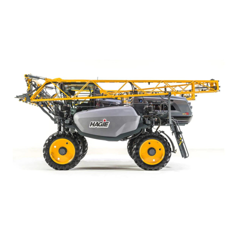
Hagie UpFront STS 16 User manual

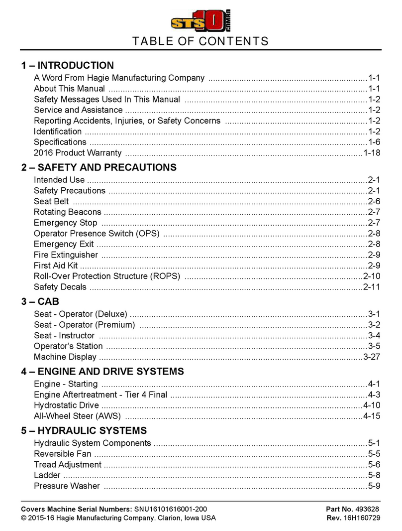
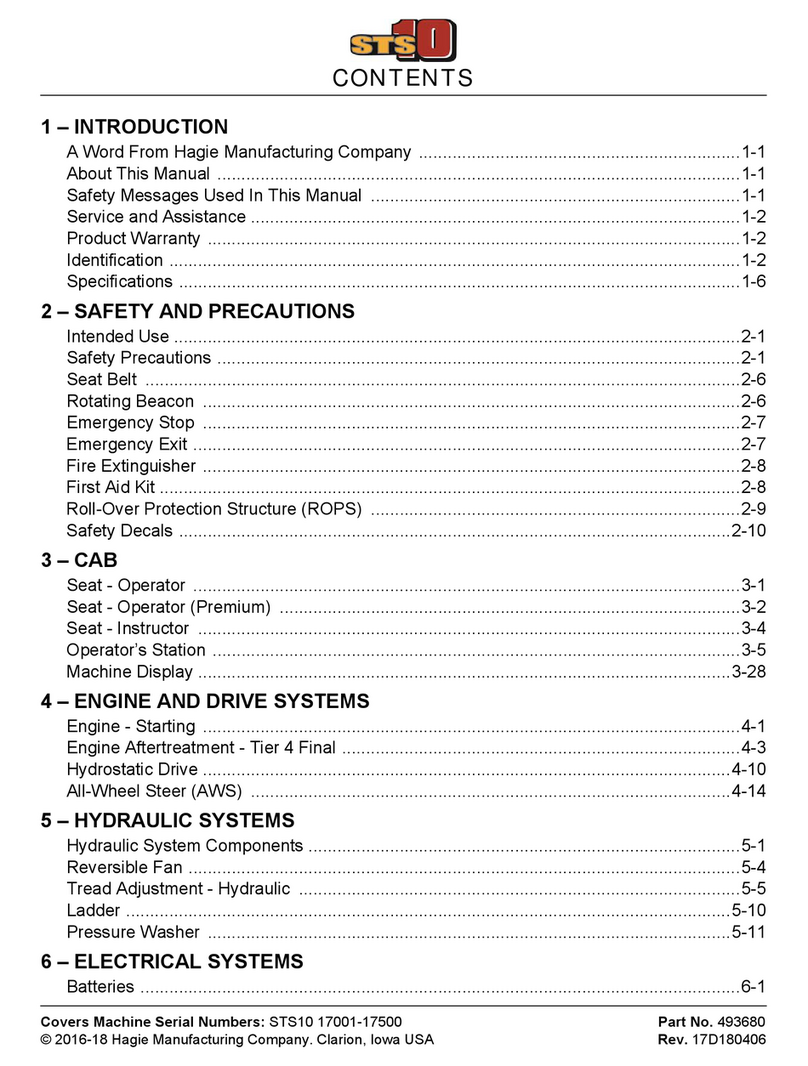
CONTENTS
5 - DASH / AUTO
Covers Machine Serial Numbers: STS16 17001-17500 Part No. 493692
© 2017-18 Hagie Manufacturing Company. Clarion, Iowa USA Rev. 17G180406
1 – INTRODUCTION
A Word From Hagie Manufacturing Company ...................................................................1-1
About This Manual .............................................................................................................1-1
Safety Messages Used In This Manual .............................................................................1-1
Service and Assistance ......................................................................................................1-2
Product Warranty ...............................................................................................................1-2
Identification .......................................................................................................................1-2
Specifications .....................................................................................................................1-6
2 – SAFETY AND PRECAUTIONS
Intended Use ......................................................................................................................2-1
Safety Precautions .............................................................................................................2-1
Seat Belt ............................................................................................................................2-6
Rotating Beacon ................................................................................................................2-6
Emergency Stop ................................................................................................................2-7
Emergency Exit ..................................................................................................................2-7
Fire Extinguisher ................................................................................................................2-8
First Aid Kit .........................................................................................................................2-8
Roll-Over Protection Structure (ROPS) .............................................................................2-9
Safety Decals ...................................................................................................................2-10
3 – CAB
Seat - Operator ..................................................................................................................3-1
Seat - Operator (Premium) ................................................................................................3-2
Seat - Instructor .................................................................................................................3-4
Operator’s Station ..............................................................................................................3-5
Machine Display ...............................................................................................................3-28
4 – ENGINE AND DRIVE SYSTEMS
Engine - Starting ................................................................................................................4-1
Engine Aftertreatment - Final Tier 4 ...................................................................................4-3
Hydrostatic Drive ..............................................................................................................4-10
All-Wheel Steer (AWS) ....................................................................................................4-15
5 – HYDRAULIC SYSTEMS
Hydraulic System Components ..........................................................................................5-1
Reversible Fan ...................................................................................................................5-5
Tread Adjustment - Hydraulic ............................................................................................5-6
Ladder ..............................................................................................................................5-10
Pressure Washer .............................................................................................................5-11
6 – ELECTRICAL SYSTEMS
Batteries .............................................................................................................................6-1

Battery Disconnect Switch .................................................................................................6-3
Battery Tender ...................................................................................................................6-4
Fuses and Relays ..............................................................................................................6-5
Fuse and Relay Ratings ...................................................................................................6-10
Video Camera Input Connections ....................................................................................6-13
7 – SPRAY SYSTEMS
Spray Boom Hose Ring Installation ...................................................................................7-1
Spray Booms - 90/100’ ......................................................................................................7-2
Spray Booms - 120/132’ ..................................................................................................7-13
Spray Boom - Rear ..........................................................................................................7-26
Solution System Components ..........................................................................................7-28
Solution System - Operation ............................................................................................7-37
Fence Row Applicator ......................................................................................................7-40
Filling Your Solution Tank ................................................................................................7-41
Draining Your Solution Tank ............................................................................................7-47
Rinse System ...................................................................................................................7-48
Foam Marker System .......................................................................................................7-52
Modular Injection System .................................................................................................7-55
Application .......................................................................................................................7-64
8 – DUAL PRODUCT SPRAY SYSTEMS
Solution System Components - Dual Product ....................................................................8-1
Solution System Operation - Dual Product ......................................................................8-12
Rinse System - Dual Product ...........................................................................................8-17
Filling Your Solution Tank - Dual Product ........................................................................8-30
Draining Your Solution Tank - Dual Product ....................................................................8-34
Application - Dual Product ...............................................................................................8-35
9 – MAINTENANCE AND STORAGE
Service - Fluids ..................................................................................................................9-1
Service - Filters ................................................................................................................9-10
Service - Lubrication ........................................................................................................9-22
Service - Engine Drive Belt ..............................................................................................9-27
Service - Bolt Torque .......................................................................................................9-28
Service - Toe-In ...............................................................................................................9-30
Service - Miscellaneous ...................................................................................................9-32
Service Intervals ..............................................................................................................9-36
Storage ............................................................................................................................9-40
10 – MISCELLANEOUS
Transporting .....................................................................................................................10-1
Lifting Your Machine ........................................................................................................10-4
Quick-Tach System - Spray Booms .................................................................................10-6
Air Suspension Exhaust .................................................................................................10-17
Hand Wash System .......................................................................................................10-18
Hood Operation ..............................................................................................................10-20

Ladder - Fuel Fill ............................................................................................................10-21
Tall Crop Package - Installation .....................................................................................10-24
Troubleshooting .............................................................................................................10-37

1-1
5 - DASH / AUTO
SECTION 1 – INTRODUCTION
A WORD FROM HAGIE
MANUFACTURING COMPANY
Congratulations on the purchase of your STS
Sprayer! Read this operator’s manual and
become familiar with operating procedures and
safety precautions before attempting to operate
your sprayer.
As with any piece of equipment, certain
operating procedures, service, and maintenance
are required to keep your machine in top running
condition. We have attempted herein to cover all
of the adjustments required to fit varying
conditions. However, there may be times when
special care must be considered.
NOTE: The operator is responsible for
inspecting the machine and its
attachments, as well as having parts
repaired or replaced when continued use
of the product causes damage or
excessive wear to other parts.
Hagie Manufacturing Company reserves the
right to make changes in the design and material
of any subsequent sprayer without obligation to
existing units.
Thank you for choosing a Hagie sprayer and
we ensure you of our continued interest and
support in its optimal performance for you. We
are proud to have you as a customer!
ABOUT THIS MANUAL
This manual will aid you in the proper
operation and service of your machine. It is the
responsibility of the user to read the operator’s
manual and comply with the correct and safe
operating procedures, as well as maintain the
product according to the service information
provided in the Maintenance and Storage
Section elsewhere in this manual.
Photographs and illustrations used in this
manual are of general nature only. Some of the
equipment and features shown may not be
available on your machine.
Information described in this manual was
correct at the time of printing. Because of Hagie
Manufacturing Company’s continuous product
improvement, certain information may not be
included in this manual. To obtain the most
current operator’s manual for your machine,
please visit www.hagiehelp.com.
Keep this manual in a convenient place for
easy reference. This manual is considered a
permanent fixture of the product. In the event of
resale, this manual must accompany the
machine.
If you do not understand any part of this
manual or require additional information or
service, contact your local John Deere dealer for
assistance.
SAFETY MESSAGES USED IN
THIS MANUAL
The following safety messages found
throughout this manual alert you of situations
that could become potentially dangerous to the
operator, service personnel, or equipment.
NOTICE
Any pictures or illustrations contained
within this manual that depict situations
with shields, guards, rails, or lids
removed are for demonstration only.
Keep all shields and safety devices in
place at all times.
DANGER
This symbol indicates a hazardous
situation which, if not avoided, will result
in serious injury or death.
1-2
SECTION 1 –
INTRODUCTION
NOTE: A “Note” is intended to make special
mention of, or remark on.
SERVICE AND ASSISTANCE
Please contact your local John Deere
dealer for service and assistance.
PRODUCT WARRANTY
Please contact your local John Deere
dealer for further information.
IDENTIFICATION
Each machine is identified by means of a
frame serial number. This serial number
denotes the model, year in which it was built,
and the number of the sprayer.
For further identification, the engine,
solution pump, hydraulic pumps, and
attachments each have serial numbers, and
the planetary wheel hubs have identification
plates that describe the type of mount and
gear ratio.
To ensure prompt, efficient service when
ordering parts or requesting service repairs,
record the serial numbers and identification
numbers in the following spaces provided.
Machine
The machine serial number is stamped on
the front right-hand side of frame (behind the
front leg).
WARNING
This symbol indicates a potentially
hazardous situation which, if not
avoided, could result in moderate/
serious injury or death.
CAUTION
This symbol indicates a potentially
hazardous situation which, if not
avoided, may result in minor or
moderate injury. It may also be used to
alert against unsafe practices.
NOTICE
This symbol indicates operator
awareness which, if not avoided, may
result in personal or property damage.
NOTICE
Reference to right and left-hand used
throughout this manual refers to the
position when seated in the operator’s
seat facing forward.
Machine Serial Number
-Typical View
Serial No. _______________________

SECTION 1 –
INTRODUCTION
1-3
Engine
The engine has an identification plate
located on the right-hand side (above
batteries) that provides engine serial
number, as well as other manufacturer
information. Refer to your Parts Manual for
specific part number.
Solution Pump
The solution pump has an identification
plate mounted on the side of pump that
provides pump serial number, as well as
other manufacturer information. Refer to your
Parts Manual for specific part number.
Hydraulic Pumps
The PC, LS, Fan, and Drive Pumps each
have an identification plate mounted on the
side of pump that provides pump serial
number, as well as other manufacturer
information. Refer to your Parts Manual for
specific part number.
Engine Identification Plate
-Typical View
Serial No. _______________________
Solution Pump Identification Plate
* View shown from beneath machine
-Typical View
Serial No. _______________________

1-4
SECTION 1 –
INTRODUCTION
Wheel Motors
The wheel motors each have an
identification plate mounted on the side of
motor that provides motor serial number, as
well as other manufacturer information. Refer
to your Parts Manual for specific part
number.
Wheel Hubs
The wheel hubs each have an
identification plate mounted on the front of
hub that provides hub serial number, as well
as other manufacturer information, including
gear ratio. Refer to your Parts Manual for
specific part number.
• Drive
Pump
•PC
Pump
• Fan
Pump
•LS
Pump
Hydraulic Pumps
* Top view shown
-Typical View
_______________________ PC Pump
_______________________ Fan Pump
_______________________ LS Pump
_______________________ Drive Pump
Wheel Motor Identification Plates
-Typical View
_______________________ Right Front
_______________________ Right Rear
_______________________ Left Front
_______________________ Left Rear

SECTION 1 –
INTRODUCTION
1-5
Spray Boom
Steel Spray Booms (90/100’)
The steel spray boom serial number is
stamped on the bottom right-hand side of
transom.
Aluminum Spray Booms (120/132’)
The aluminum spray boom serial number
is stamped on the lower right-hand side of
fixed transom.
Wheel Hub Identification Plate
-Typical View
_______________________ Right Front
_______________________ Right Rear
_______________________ Left Front
_______________________ Left Rear
Steel Spray Boom Serial Number
-Typical View
Serial No. _______________________
Aluminum Spray Boom Serial Number
-Typical View
Serial No. _______________________

1-6
SECTION 1 –
INTRODUCTION
SPECIFICATIONS
NOTE: Dimensions on your machine may vary, depending on tire size.
Detail Description Specification
90-ft.
Boom
100- ft.
Boom
120-ft.
Boom
132-ft.
Boom
AOverall Sprayer Height (from top of cab)
NOTE: Overallmachine height dimension does not
include the cab-mounted rotating
beacons or the optional GPS unit.
151.5” **
(384.8 cm) **
151.5” **
(384.8 cm) **
151.5” **
(384.8 cm) **
151.5” **
(384.8 cm) **
B Raised Transom Height 152.5” **
(387.4 cm) **
(from top of lights)
152.5” **
(387.4 cm) **
(from top of lights)
152.5” **
(387.4 cm) **
(from top of fixed
transom)
152.5” **
(387.4 cm) **
(from top of fixed
transom)
C3 Transom Lift Range (C1 minus C2) 86”
(104” - 18”)
218.4 cm
(264.2-45.7 cm)
86”
(104” - 18”)
218.4 cm
(264.2-45.7 cm)
86”
(104” - 18”)
218.4 cm
(264.2-45.7 cm)
86”
(104” - 18”)
218.4 cm
(264.2-45.7 cm)
D Static Loaded Hub Height 38 3/8” **
(97.5 cm) **
38 3/8” **
(97.5 cm) **
38 3/8” **
(97.5 cm) **
38 3/8” **
(97.5 cm) **
EWheel Base 166” (421.6 cm) 166” (421.6 cm) 166” (421.6 cm) 166” (421.6 cm)
F Sprayer Length
NOTE: Overall machine length will vary, depending
on boom size. Dimensions do not
include the optional rear boom.
336” (853.4 cm) 336” (853.4 cm) 370” (939.8 cm) 410” (1041.4 cm)
GWidth
(booms folded, 120”/304.8 cm tread)
144” (365.8 cm) 144” (365.8 cm) 169” (429.3 cm) 169” (429.3 cm)
H Frame Clearance (to tread adjust bolts) 73” (185.4 cm) ** 73” (185.4 cm) ** 73” (185.4 cm) ** 73” (185.4 cm) **
ILower Leg Clearance (from shield) 29.5” (74.9 cm) ** 29.5” (74.9 cm) ** 29.5” (74.9 cm) ** 29.5” (74.9 cm) **
J Tread Width* 120” - In **
(304.8 cm - In) **
160” - Out **
(406.4cm - Out) **
120” - In **
(304.8 cm - In) **
160” - Out **
(406.4cm - Out) **
120” - In **
(304.8 cm - In) **
160” - Out **
(406.4cm - Out) **
120” - In **
(304.8 cm - In) **
160” - Out **
(406.4cm - Out) **
Illustration shown with 120-ft. boom

SECTION 1 –
INTRODUCTION
1-7
* Tread width is measured from center of tire at
ground.
** Refer to “Tire Specifications” provided else-
where in this section for a complete listing of tire
options when configuring machine specifications
on your model.
General Information
•Frame Type: 4 x 8” (10.2 x 20.3 cm)
modular platform frame
•Suspension: 4-wheel, individual, auto
air-ride
•Shipping Width:
- 144”/365.8 cm (with 90/100’ boom)
- 169”/429.3 cm (with 120/132’ boom)
•Approximate Dry Weight:
- 24,249 lbs./10,999 kg (machine only)
- 28,589 lbs./12,967 kg (with 90’ boom)
- 30,109 lbs./13,657 kg (with 120’ boom)
NOTICE
Because Hagie Manufacturing
Company offers a variety of options, the
illustrations in this manual may show a
machine equipped other than standard.
Height and weight values may vary,
depending on available equipment.

1-8
SECTION 1 –
INTRODUCTION
Spray System GPS Specifications
-If Equipped
NOTE: Dimensions on your machine may vary, depending on tire size.
Detail Description Specification
AWheel Base 166” (421.6 cm)
B Static Loaded Hub Height 38 3/8” (97.5 cm)
COverall Sprayer Height (from middle of GPS unit) 155” (393.7 cm)
D Length
(from front of boom spray tips to center of GPS unit)
129.8” (329.7 cm)
ELength (from center of GPS unit to center of rear hub) 138.8” (352.6 cm)

SECTION 1 –
INTRODUCTION
1-9
Settings and Calibration
Record settings and calibration values
used in the following spaces provided when
programming your spray system console.
Refer to this information for future reference.
Circle the selected setting on the spray system console for the following options:
Record calculated calibration values in the spaces provided below.
Units • US (Acres) • SI (Hectares) • Turf
(1,000 sq. ft./
92 sq. m)
Speed
Sensor
• SP1 (Wheel Speed) • SP2 (Radar/GPS)
Control Type • Liquid Spray • Gran 1
(Single Belt
Bed)
• Gran 2
(Split Belt
Bed/Single
Encoder)
• Gran 3
(Split Belt
Bed/Dual
Encoders)
• Spinner RPM
Control
Valve Type • Standard
Valve
•Fast Valve • Fast Close
Valve
• Pulse Width
Modulated
Valve
• Pulse Width
Modulated
Close Valve
Speed Cal Section
Widths
Meter Cal Rate Cal Valve Cal Tank Volume
1. 1. 1. 1. 1. 1.
2. 2. 2. 2. 2.
3. 3. 3. 3. 3.
4. 4. 4. 4. 4.
5. 5. 5. 5. 5.
6.
7.
8.
9.
10.

1-10
SECTION 1 –
INTRODUCTION
Description Specification
Engine
Manufacturer John Deere
Model Final Tier 4 PSS 9.0L
Type • Electronic w/Air-to-Air Cooler and Dual Turbo
Charger
• Diesel Oxidation Catalyst/Diesel Particulate
Filter (DOC/DPF)
• Cooled Exhaust Gas Recirculation (EGR)
• Selective Catalytic Reduction (SCR)
Number of Cylinders 6
Displacement 9.0L (549 c.i.)
Horse Power • 375 hp (279 kW) @2200 rpm
• 413 hp (308 kW) @2000 rpm (peak power)
Fuel Type Ultra-Low Sulfur Diesel (ULSD)
Fuel System Filtered, Direct-Injected
Air Cleaner Dry-Type, Dual Element
Engine Air Filter Restriction Monitors Engine Control Unit (ECU)
Slow Idle 850 RPM
Fast Idle (no load) 2200 RPM
Hydrostatic Drive
Hydrostatic Pump Danfoss H1-Series
Drive Train All-Wheel 4-Wheel Drive
Speed Ranges Speed Ranges 1-20 (operator selected)
• Solution Tank Transport Limit
(Transportation Tank Level Switch)
600 gallons (2271L)
Hydrostatic Wheel Motors Danfoss H1-Series
Final Drives Planetary Gear Reduction Hubs (Fairfield C017)
• Lubrication Oil Bath
Brakes (Parking) Multiple Disk, Spring Applied, Hydraulically
Released
Brakes (Friction) Hydraulically Applied (Front Wheels), Internal to
Hubs
Auxiliary Hydraulic System
Steering System Hydraulic, Priority Circuit, PC Pump

SECTION 1 –
INTRODUCTION
1-11
• Control Full-Time Power
• Steering Cylinders Double Acting (w/dynamic alignment system*)
* Under normal field conditions
• Turning Radius^
NOTE: May vary, depending on tire size. • 27 ft./8 m (No AWS/AWS “Off”)
• 20 ft./6 m (AWS “On”, if equipped)
All Wheel Steer (AWS) - if equipped^ Coordinated Steering
Solution System Hydraulic Pump Load Sense (LS) Pump
Cooling Fan Hydraulic Pump Hydrostatic Closed-Loop Pump
Spray System
Booms 90/100/120/132-ft. (9 sections)
• Type 1” (2.5 cm) Schedule 5 Stainless Wet Boom
Plumbing
• Controls Electro-Hydraulic (fold/lift/level)
• Level Shock Absorber Gas-Charged Accumulator
• 90/100-ft. Outer Boom Hydraulic Breakaway Self-Actuated, Auto Reset
• 120/132-ft. Inner Boom Breakaway Hydraulic, Manual Reset
• 120/132-ft. Outer Boom Breakaway Mechanical w/Spring, Auto Reset
Solution Fill Connection
• Quick-fill Connection 3” (7.6 cm) Inner Diameter
Solution Tank Stainless Steel
Agitation Jet-Type w/Electric Valve Variable Control
General Spray System
• Pump • Centrifugal-Hydraulically Driven w/Proportional
Control Valve
• Hypro® 9306-HM1C-BU w/Silicon Carbide
Seals
• 3” (7.6 cm) Inlet/2” (5.1 cm) Outlet Plumbing
• Flow Meter Electromagnetic: 3-190 GPM (11.4-719.2 l/min)
• Boom Solution Valves Ball Valves, Electric Actuation, Stainless Ball/
Stem, PTFE Seats
• Pressure Gauge 100 PSI (6.9 bar), Glycerin Filled
• Console • Raven (optional)
• Ag Leader® (optional)
• John Deere (optional)
• Fence Row Nozzle Remote Activated (left and right)
• Rear Nozzle Remote Activated
Solution Circuit Pressure (Maximum) 100 PSI (6.9 bar)

1-12
SECTION 1 –
INTRODUCTION
Modular Injection System (if equipped)
Chemical Tank(s) 55 gallons (208L)/each
Injection Pump(s) Raven Sidekick Pro™ (5-200 oz./min.)
Mixer 3” (7.6 cm) Poly
Foam Marker System (if equipped)
Make Hagie Concentrate Foamer
Type Boom Mix
Rinse System
Spray System Rinse
(solution tank, pump, and booms)
2 Rotating Rinse Balls (inside tank)
Air Purge - if equipped Remote Activated (purges pump suction line,
pump, and boom plumbing)
Dual Product Spray System (if equipped)
Boom Plumbing •Single Product System (9-section 1”/2.5 cm
schedule 5 stainless wet boom plumbing)
•Dual Product System (5-section 1”/2.5 cm
schedule 5 stainless wet boom plumbing)
Solution Tank • Stainless Steel
• 1600-gal./6056L (split)
(Tank 1 = 1000-gal./3785L, Tank 2 = 600-gal./
2271L)
Agitation Jet-Type w/Electric Valve Variable Control
Solution Quick-Fill Connection 3” (7.6 cm) Inner Diameter
General Spray System
• Solution Pump (2) • Centrifugal-Hydraulically Driven w/Proportional
Control Valve
• Hypro® 9306-HM1C-BU w/Silicon Carbide
Seals
• 3” (7.6 cm) Inlet; 2” (5.1 cm) Outlet Plumbing
• Flow Meter (2) Electromagnetic: 3-190 GPM (11.4-719.2 l/min)
• Boom Solution Valves (2) Ball Valves, Electric Actuation, Stainless Ball/
Stem, PTFE Seats
• Pressure Gauge (2) 100 PSI (6.9 bar), Glycerin Filled
•Console •Raven
• Ag Leader®
Solution Circuit Pressure (Maximum) 100 PSI (6.9 bar)
Rinse System
• Spray System Rinse
(solution tank, pumps, and booms)
Rotating Rinse Ball (inside each side of tank)

SECTION 1 –
INTRODUCTION
1-13
• Air Purge - if equipped Remote Activated (purges pump suction line,
pump, and boom plumbing)
• Rinse Tank • Polyethylene
• 100-gal. (378L)
Electrical System
General Electrical System
• Battery Dual 12V, Negative Ground (CCA)
• Alternator 240 AMP, Voltage Regulated
• Starter 12V w/Solenoid
Lights (Exterior)
• Front of Cab 2 Trapezoidal Headlights, 2 Floodlights, 2
Rotating Amber Beacon Lights
• Transom 2 Trapezoidal Headlights
• Quick-Tach Mount 2 Trapezoidal Headlights (high/low beam), 2
Oval Amber Lights (combined)
• Boom Cradle 2 Trapezoidal Floodlights (1 on each cradle), 2
Oval Amber Lights (1 on each cradle)
• Rear Engine Hood 2 Round Red Lights, 2 Round Amber Lights
• Spray Boom Indicators
(located on boom, if equipped)
1 Oval White Light, 2 Oval Amber Lights, 9 Oval
Red Lights
• Night Spray - if equipped 2 Trapezoidal Lights (1 on each main boom fold
section)
Cab and Instruments
Sound Level (cab interior) 86 dBA (maximum)
Cab (General) Tilt Steering, Wipers/Washers, Dual Side
Mirrors, Dome Light, Tinted Glass, Instructor
Seat
Temperature Control Full Range
A/C Charge Type R-134A
Fresh Air Filtration • RESPA® Cab Filter
• Charcoal Filter
Seat Air-Ride
Instruments Tachometer (rpm), Fuel Level, Engine Coolant
Temperature, Aftertreatment Level

1-14
SECTION 1 –
INTRODUCTION
^ Operators with machines equipped with All-Wheel Steer (AWS) pay special attention.
Machine Display Hour Meter, Battery Voltage, Engine Oil
Pressure, Ground Speed, Engine Diagnostics,
Tread Adjustment, Parking Brake, Machine/
Engine Malfunction Warnings, Engine Exhaust
Filtration Warning, High Exhaust Temperature
Warning, Low Hydraulic Oil Level, Low Coolant
Level, Low Fuel Level, Cab Air Pressure
Stereo AM/FM Radio w/CD, MP3, and Bluetooth
Fluid Capacities
Solution Tank 1600 gallons (6056L)
Fuel Tank 150 gallons (567L)
Engine Oil Pan
(including filter, remote lines, and cooler)
34.4 quarts (32.6L), John Deere Plus-50™ II
NOTE: John Deere Break-In™Plus special-purpose
engine oil is to be used during the initial break-in
period (first 500 hours of operation). Thereafter, John
Deere Plus-50 II premium engine oil is to be used.
Engine Oil Dipstick (L-H mark) 2.3 quarts (2.2L)
Engine Cooling System
(including block, lines, and radiator)
11 gallons (41L), John Deere Cool -Gard™ II
Diesel Exhaust Fluid (DEF) Tank
(Final Tier 4 Engines)
7.8 gallons (29.5L), John Deere Diesel Exhaust
Fluid (DEF)
Hydraulic Oil
(including lines, filter, cooler, etc.)
50 gallons (189L), John Deere Hy-Gard™
Hydraulic Oil Reservoir 34 gallons (128L)
Wheel Hubs (4) • 56 oz./1.7 L (w/o service brake)
• 50 oz./1.5 L (w/ service brake)
NOTE: The above fluid capacities apply when filling a
wheel hub for the first time. Refilling after
draining during an oil change would require
fewer ounces.
Oil Type: Mobiltrans™ AST oil (CAT T0-4 rated)
Rinse System Tank 100 gallons (378.5L)
Hand Wash Tank 4 gallons (15L)
Foam Marker Tank 1 gallon (3.8L), Foam Concentrate
Air Conditioning System (Charge) 4.00 lbs. (1.81 kg), R-134A

SECTION 1 –
INTRODUCTION
1-15
* Static load radius is suggested and will vary with load.
TIRE SPECIFICATIONS (STANDARD)
Size Make Model Load
Rating
(Weight/
Speed)
Air
Pressure
(Max PSI)
Tread
Width
(in.)
Load
Capacity
(lbs.)
Overall
Diameter
(in.)
Static
Load
Radius*
(in.)
Rolling
Circum.
(in.)
Gross
Flat
Plate
(in2)
650/65R38 Alliance 550 166D 46 25.4 13,220 71.4 32.4 214.6 - - -
IF380/90R46 Alliance 363 168D 64 15.3 12,330 72.5 33.6 220.8 - - -
IF480/80R50 Alliance 363 166D 44 18.9 14,010 80.2 37.0 242.2 - - -
650/65R38 Firestone® 9000 166D 46 26.0 9,100 72.4 32.4 218.0 480
VF380/105R50 Firestone Radial All
Trac RC
179D 64 16.2 17,100 80.7 37.3 244.0 327
380/90R46 Goodyear Ultra
Sprayer
168A8 78 15.0 12,300 72.7 32.8 219.0 - - -
IF320/105R54 Goodyear Ultra
Sprayer
167D 64 12.9 12,000 80.1 35.4 236.0 215
IF380/105R50 Goodyear Ultra
Sprayer
177D 70 14.9 16,100 80.7 36.1 241.0 305
IF520/85R42 Goodyear Ultra Torq 170A8 52 20.3 13,200 76.5 34.3 230.0 - - -
480/80R42 Goodyear Dyna Torq 166A8 58 18.7 11,700 73.3 33.3 221.0 - - -
VF380/90R46 Michelin® Spraybib 173D 64 15.1 14,330 72.5 33.4 217.7 267
VF420/95R50 Michelin Spraybib 177D 52 16.3 16,094 80.8 36.9 240.9 - - -
VF480/80R50 Michelin Yieldbib 166B 23 18.4 11,680 80.3 35.5 237.6 450

1-16
SECTION 1 –
INTRODUCTION
* Static load radius is suggested and will vary with load.
TIRE SPECIFICATIONS (METRIC)
Size Make Model Load
Rating
(Weight/
Speed)
Air
Pressure
(Max
Bar)
Tread
Width
(cm)
Load
Capacity
(kg)
Overall
Diameter
(cm)
Static
Load
Radius*
(cm)
Rolling
Circum.
(cm)
Gross
Flat
Plate
(cm2)
650/65R38 Alliance 550 166D 3.2 64.5 5,996 181.4 82.3 545.1 - - -
IF380/90R46 Alliance 363 168D 4.4 38.9 5,592 184.2 85.3 560.8 - - -
IF480/80R50 Alliance 363 166D 3.0 48.0 6,354 203.7 94.0 615.2 - - -
650/65R38 Firestone 9000 166D 3.2 66.0 4,127 183.9 82.3 553.7 3096.8
VF380/105R50 Firestone Radial All
Trac RC
179D 4.4 41.1 7,756 205.0 94.7 619.8 2109.7
380/90R46 Goodyear Ultra
Sprayer
168A8 5.4 38.1 5,579 184.7 83.3 556.3 - - -
IF320/105R54 Goodyear Ultra
Sprayer
167D 4.4 32.8 5,443 203.5 89.9 599.4 1387.1
IF380/105R50 Goodyear Ultra
Sprayer
177D 4.8 37.8 7,302 205.0 91.7 612.1 1967.7
IF520/85R42 Goodyear Ultra Torq 170A8 3.6 51.6 5,987 194.3 87.1 584.2 - - -
480/80R42 Goodyear Dyna Torq 166A8 4.0 47.5 5,307 186.2 84.6 561.3 - - -
VF380/90R46 Michelin Spraybib 173D 4.4 38.4 6,500 184.2 84.8 553.0 1722.6
VF420/95R50 Michelin Spraybib 177D 3.6 41.4 7,300 205.2 93.7 611.9 - - -
VF480/80R50 Michelin Yieldbib 166B 1.6 46.7 5,298 204.0 90.2 603.5 2903.2

SECTION 1 –
INTRODUCTION
1-17
NOTE: There are no adjustments to the loads and pressures in the above table for lower speeds
or stationary service.
NOTE: Minimum inflation pressures for IF agricultural tires used as singles = 12 psi.
TIRE LOAD LIMITS (LBS) AT VARIOUS COLD INFLATION PRESSURES (PSI)
Inflation
(psi)
6 9 12 15 17 20 23 26 29
650/65R38 Alliance N/A N/A 5,880 N/A 7,440 N/A 8,810 N/A 10,040
IF380/90R46 Alliance N/A N/A 4,270 N/A 5,460 6,170 6,720 N/A 7,310
IF480/80R50 Alliance N/A N/A 5,810 6,520 7,310 8,260 9,030 9,520 9,780
650/65R38 Firestone 4,180 5,080 5,840 6,800 7,600 8,250 9,100 9,650 9,900
VF380/105R50 Firestone 4,680 5,520 6,400 7,400 8,250 9,350 10,200 10,700 11,400
380/90R46 Goodyear N/A 3,300 3,860 4,400 5,080 5,520 6,150 6,400 6,800
IF320/105R54 Goodyear N/A N/A 4,540 5,080 5,840 6,400 7,150 7,400 7,850
IF380/105R50 Goodyear N/A N/A 5,520 6,400 7,150 8,050 8,800 9,100 9,650
IF520/85R42 Goodyear N/A N/A 6,950 7,850 8,800 9,900 10,700 11,400 11,700
480/80R42 Goodyear N/A 4,080 4,800 5,520 6,150 6,950 7,600 8,050 8,250
VF380/90R46 Michelin N/A N/A N/A N/A N/A N/A N/A N/A N/A
VF420/95R50 Michelin N/A N/A N/A N/A N/A N/A N/A 11,350 11,830
VF480/80R50 Michelin 5,200 6,240 7,290 7,330 9,370 10,530 11,680 N/A N/A
TIRE LOAD LIMITS (LBS) AT VARIOUS COLD INFLATION PRESSURES (PSI) - CONTINUED
Inflation
(psi)
35 41 46 52 58 64 70 75
650/65R38 Alliance 11,170 12,220 13,220 N/A N/A N/A N/A N/A
IF380/90R46 Alliance 7,780 8,520 9,270 9,780 10,330 11,230 N/A N/A
IF480/80R50 Alliance 10,620 N/A N/A N/A N/A N/A N/A N/A
650/65R38 Firestone 10,700 11,700 N/A N/A N/A N/A N/A N/A
VF380/105R50 Firestone 12,000 13,200 13,900 15,200 15,700 17,100 N/A N/A
380/90R46 Goodyear 7,150 7,850 8,550 9,100 9,650 10,500 11,400 12,000
IF320/105R54 Goodyear 8,250 9,100 9,650 N/A 11,000 12,000 N/A N/A
IF380/105R50 Goodyear 10,200 11,400 12,000 N/A 13,600 14,800 16,100 N/A
IF520/85R42 Goodyear 12,800 N/A N/A N/A N/A N/A N/A N/A
480/80R42 Goodyear 8,800 9,650 10,500 11,000 11,700 N/A N/A N/A
VF380/90R46 Michelin 9,650 11,020 12,020 12,790 13,230 14,330 N/A N/A
VF420/95R50 Michelin 12,790 14,000 15,210 16,090 N/A N/A N/A N/A
VF480/80R50 Michelin N/A N/A N/A N/A N/A N/A N/A N/A
Other manuals for UpFront STS 16
1
Table of contents
Other Hagie Paint Sprayer manuals

Hagie
Hagie STS12i Combo User manual

Hagie
Hagie SmarTrax 2100 Series User manual

Hagie
Hagie STS 10 Combo User manual

Hagie
Hagie UpFront STS 14 Combo User manual

Hagie
Hagie DTS 10 User manual

Hagie
Hagie STS 10 User manual

Hagie
Hagie DTS 10 User manual

Hagie
Hagie STS 10 Combo User manual

Hagie
Hagie STS/DPS Series User manual

Hagie
Hagie STS12i Combo User manual