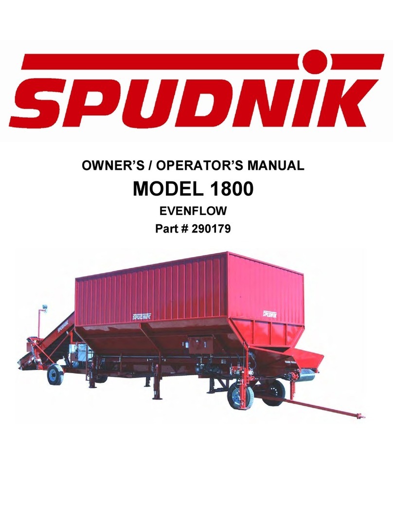
Spudnik 991 Owner's manual

Owner/Operator Manual
Ser # 991-55-5
MODEL 991
Custom Eliminator

Operating Manual Overview
The purpose of this Spudnik Operating Manual is to make the
user familiar with this machine and to assure the machine is used
for what it has been designed to do.
This Operating Manual contains important information on how to
operate this machine properly and efficiently while maintaining all
safety regulations. Observing and practicing the information
within this Manual can effectively prevent danger, reduce repair
costs and downtimes, while increasing reliability and service life
of the machine.
The Operating Manual must always be available to users
wherever the machine is in use.
The Operating Manual must be read and applied by all persons
working on/with the machine, e.g.
Operation - including set-up, troubleshooting, care, etc.
Maintenance – servicing, inspection, repair.
Transport
Operator's Manual Model 991
Page 1

Operator's Manual Model 991
Page 2
Operator's Manual Model 991
Page 2

Warranty Policy .........................................................................................4
Safety ...........................................................................................................5
General Safety Practices ............................................................................6
Hydraulics Safety Practices .......................................................................7
Transporting Safety Practices ...................................................................8
Operation Safety Practices ........................................................................9
Safety Labels .............................................................................................10
Maintenance ..............................................................................................12
Machine Parts Breakdown ……….……………....……………………..14
Schematics ………......................................................................................52
Table of Contents
Operator's Manual Model 991
Page 3

Limited Warranty Policy for New Spudnik Machinery
Spudnik Equipment Company LLC (“Spudnik”) warrants to the original purchaser eachnew Spudnik machine to be free from defects in
material and workmanship. Spudnik will repair or replace, at its option, any part coveredby this warrantythat is found to be defective
during the warranty period outlined below. Warranty service must be performed by an authorized dealer or representative of Spudnik. This
warranty is applicableonly for the normal service life expectancyof the product or components, as noted in the following table. Once the
warranty period has begun, it cannot be stopped or interrupted.
What is included in the Spudnik Warranty:
Product Warranty Term
180 Days from 1st day of operationor 720 Hours of machine
Rollers, Sprockets,Roller Chain, Belt Lacing, and Bearings operation, whichever comes first
All paint to include: Insufficient coverage, failure of paint adherence, and excessive runs. 12 Months from date of delivery of new Spudnik product to
NOTE: Excessive runs not to exceedmore than 15% of the painted surfaceon the the original retail customer
machine. 12 Months from date of delivery of new Spudnik product to
All other materials and workmanship (except asnoted below)the original retail customer
30 days from date of purchase, or the remainder of the
Genuine Spudnik replacement partsand components original equipment warranty period, whichever is longer
Those items that are excluded from this warranty are as follows:
(1) any merchandise or components thereof, which, in the opinion of the company have been subject to: (a) Rock chip damage and other
abuse to painted surfaces, (b) damage caused by weather (to include UV damage), accident, or acts of God, (c) any product that has been
altered or modified in ways not approved by Spudnik Equipment Company LLC., (d) depreciation or damage caused by normal wear, lack
of reasonable and proper maintenance, misuse, failureto follow the product’s Operator Manual recommendations, (e) Using machine for
other than normal moving of agricultural products during planting, harvest, and processing seasons. Agricultural products to include:
Potatoes, beets, onions, carrots, grains, etc., (2) Used products, (3) Repairs made by unauthorized dealers.
To Obtain Warranty Service
To be eligible for the Spudnik warranty, purchaser must: (a) Havealready remitted payment in full (b) have filled out and submitted the
Spudnik Delivery Declaration form to a Spudnik representative (c) report the product defect to an authorized dealer or Spudnik sales
representative and request repair within 30 days of noticing the defect and (d) make the product available to the dealer or service center
within a reasonable period of time, transportation charges prepaid.
The selling dealer has no authority to make any representation or promise on behalf of Spudnik, or to modify the terms or limitations of
this warranty in any way.
Limited Warranty Statement
To the extent permitted by law, Spudnik does not make any warranty, representation, or promisesexpressor implied asto the quality,
performance, or freedom from defect of any Spudnik New Machinery. NO IMPLIED WARRANTY OF MERCHANTABILITY OR FITNESS IS
MADE. IN NO EVENT WILL SPUDNIK, AN AUTHORIZED SPUDNIK DEALER, OR ANY COMPANY AFFILIATED WITH SPUDNIK BE LIABLE
FOR INCIDENTAL OR CONSEQUENTIAL DAMAGES. This warranty is subject to any existing conditions of supply which may directly affect
our ability to obtain materials or manufacture replacement parts. Spudnik reserves the right to make improvements in design or changes in
specifications at any time, without incurring any obligation to owners of units previously sold. No one is authorized to alter, modify or
enlarge this warrantynor the exclusion,limitations and reservations.
To obtain more information, please contact your dealer or Spudnik at 1-208-785-0480.
Operator's Manual Model 991
Page 4
Operator's Manual Model 991
Page 4

SAFETY
This Safety Alert Symbol Means:
Attention!
Become Alert!
Your Safety is Involved!
This Symbol identifies important safety
information on the safety decals and in this
manual. When you see this symbol, be alert to
the possibility of injury or death.
You are responsible for the safe operation and maintenance of your Spudnik Eliminator. All operators
and anyone doing work or maintenance on the Eliminator must be trained in the operation, maintenance
procedures, and related SAFETY information contained in this manual. All operator’s and
maintenance personnel must receive this training at least annually to be in compliance with OSHA
regulation 1928.57. This manual is a guide to good safety practices that should be followed during
operation.
This Operator’s Manual is the most important safety device on the Eliminator. It is the operator’s
responsibility to read and understand ALL operating and safety instructions in this manual.
ANY UNAUTHORIZED MODIFICATIONS TO MACHINE IS CONSIDERED A BREACH OF
CONTRACT AND REMOVES ALL LIABLITY FROM THE MANUFACTURER. Unauthorized
modifications may impair the function of the machine and/or safety and could affect the life and
warranty of the Eliminator.
Think Safety! Work Safely!
The life you save could be your own!
Danger, Warning, and Caution are signal words with messages:
Danger: An immediate and specific hazard, which will result in severe injury or death if
proper precautions are not taken.
Warning: A specific hazard or unsafe practice, which could result in severe injury or death.
Caution: Unsafe practices, which could result in personal injury if proper precautions are
not taken.
Operator's Manual Model 991
Page 5

SAFETY
General Safety and Accident Prevention Regulations
The primary responsibility for safe operation of the Spudnik Eliminator is with the
owner/operator.
OSHA (Occupational Safety and Health Administration) requires that all operator’s be
trained at the time of initial assignment, and annually thereafter by the employer, in the
safe operation of the machine.
Read and understand the operator manual before operating, maintaining, or adjusting
the Eliminator.
Untrained individuals and/or children should not be allowed on or around the
Eliminator at any time.
Keep hands, feet, long hair, and clothing away from moving/rotating parts while it is
running.
Do not attempt to service, lubricate, clean, or adjust Eliminator while it is running.
Inspect all mechanisms before starting the Eliminator and replace all worn or
damaged parts.
Make sure all guards and shields are properly installed and secured before operating
the Eliminator.
Replace all worn or missing bolts with SAE Grade 5 or better unless specifically
stated otherwise.
Do not ride or mount the Eliminator while it is moving.
Do not perform maintenance on machine unless:
- Tractor is switched OFF and key is removed from ignition
- A warning sign is attached to the main switch of the machine
- Maintenance sight is secured
- Work is being done by trained individuals and someone had been appointed to
supervise
- Machine is on dry, level, and stable ground
- Proper lifting devices are used for lifting heavy loads (including hoists with adequate
load capacity and in proper working condition)
Operator's Manual Model 991
Page 6
Operator's Manual Model 991
Page 6

SAFETY
Specific Safety Instructions
Risk of injury when hitching up or unhitching machines to and from the tractor.
Never allow persons to stand between the tractor and the machine unless the towing vehicle is
secured against rolling away by means of the parking brake and/or chocks.
Secure all moving parts before transport.
Warning symbols indicate dangerous areas of the machine. Observation of the warning symbols
serves to ensure the safety of all persons working with the machine.
Hydraulic Safety Practices
When working on machine parts that are supported by hydraulic cylinders,ALWAYS support the
structure by some other means than the cylinders.
Before applying pressure to the system, make sure that all components, fittings, steel lines, and
hoses are tight and undamaged.
Wear proper eye and hand protection, and use wood or cardboard as a backstop when looking
for leaks.
A high-pressure hydraulic leak can ignite if exposed to an open flame or spark.
Seek immediate medical attention if hydraulic fluid pierces the skin. Serious toxic reactions
and/or infections may result.
Operator's Manual Model 991
Page 7

SAFETY
Transporting Safety Practices
Check to see if all bolts on tow tongue are in good condition, in place, and
secure.
Remove the pin from the towable gearbox wheel drive.
Release hydraulic pressure to the elevator lift cylinder.
It is recommended that all pups be removed from the Eliminator before
transport.
If leveling jacks are on the Eliminator, be sure that they are lifted all the way
up and are secured with 1” Bolts.
Towing speed should not exceed 20 mph due to farm rated tires and
wheels.
The slow moving vehicle sign required by the local highway and transport
authorities must be in place.
Sign must be clean and visible by overtaking and oncoming traffic.
Do not allow riders on Eliminator during transport.
Operator's Manual Model 991
Page 8
Operator's Manual Model 991
Page 8

SAFETY
Operating Safety Practices
Eliminator should be operated on a flat secure surface.
When using leveling jacks, make sure that the jacks are on secure
ground. Do not lift the wheels off of the ground.
Do not allow anyone to climb on or under the Eliminator while in
operation.
Do not put feet or hands between the picking table and dirt return
conveyor while machine is in operation.
Disconnect electrical power supply to machine when cleaning clogged
rollers or chain, removing obstructions, or removing dirt build up from
components.
Keep personnel from getting between the machine and other
machinery when placing equipment that delivers or removes product
from the Eliminator.
Do not allow anyone to pick dirt or potatoes off of the transition table
or roller table during operation. This action could result in physical
injury or death.
Properly ground all electrically operated equipment.
This machine is designated to have on operator standing on the same
side as the control panel and hydraulic drives.
Operator's Manual Model 991
Page 9

SAFETY
Safety Labels
Keep Safety labels and signs clean and legible at all times,
Replace Safety labels and signs that are missing or have become illegible.
When replacing parts that display a safety label, make sure that the new parts also
displays the safety label.
Safety labels and signs are available from your dealer’s parts department.
How to install Safety Labels
1. Be sure the installation area is clean and dry
2. Decide on the exact position before you remove the backing paper.
3. Remove the smallest portion of the split backing paper.
4. Align the label over the specified area and carefully position the small portion with the
exposed sticky backing in place.
5. Slowly peel back the remaining paper and carefully smooth the remaining portion of the
label in place.
6. Small air pockets can be pierced with a pin and smoothed using a piece of the label
backing paper.
Operator's Manual Model 991
Page 10
Operator's Manual Model 991
Page 10

MAINTENANCE
The hydraulic system used to power auxiliary functions uses AW 32 Hydraulic oil for
prime mover. Hydraulic reservoir fill level should be checked at start of each season,
and filled as needed. Hydraulic oil reservoir has a 5-gallon capacity.
Oil in hydraulic system should be drained and changed when it becomes dirty and/or
contaminated.
All wheel bearings and wheel hubs should be greased and packed at least once a
year.
Grease Steering Spindles once every week.
All bearings are of a sealed type and are lubricated by the manufacturer. Bearings will
not have grease zerks installed. One pump of grease is sufficient. Over greasing
sealed bearings will result in seal being broken and rapid failure of bearing. If seal is
broken, bearing should be greased daily until replaced.
To avoid contamination of product, hydraulic fittings must be checked daily for leaks
and replaced or tightened as necessary.
Oil in gearboxes must be checked every hundred hours of operation.
(#991214 - Oil,Lube,80/90W#4096 -15#Pail - 1 Qt=1.75lbs)
Oil should be changed when it becomes dirty and/or contaminated.
Disconnect electrical power to machine whenever maintaining, repairing, or servicing
Replace damaged or missing drive shields and safety labels at start of every season.
Proper belt alignment and tension are key to a long belt life.
Belts should be kept in alignment between conveyor sides. Alignment should be an
even distance on both sides from the belt to the conveyor sides.
BELT ALIGNMENT PROCEDURES
Belt runs to loose side (narrowest space between belt and side).
1. Tighten loose side as necessary or loosen other side as necessary.
2. Belt tension must be great enough to prevent slippage between drive pulley
and belt.
Check lug nut daily, and keep tires inflated at correct PSI.
Be sure the electrical system is setup with proper phase and adequate voltage.
Drive chains should be kept clean and tensioned correctly to prolong chain life. Ideal chain
tension should allow ½” maximum flex when deflected. Over tightening will cause damage to
bearings and sprockets. New roller chain drives should be inspected after 50 hours of
operation, and every 500 hours thereafter. During inspection, look for drive interference,
damaged chain or sprockets, loose set screws, proper sprocket alignment, chain tension, proper
lubrication, foreign material buildup, and percent elongation. To check for elongation, measure
from pin to pin and compare with new chain. When replacing chain or sprockets, it is best to
replace both at the same time.
Check V-belts for cracking and wear and replace as needed. A sign of belt wear would be a belt
that has stretched and is running in the bottom of the groove on the pulleys.
Check the hinge points and pivot bolts every 100 hours of machines operation for fatigue and
excessive wear. Replace as needed to avoid personal injury.
Operator's Manual Model 991
Page 11

OPERATING INSTRUCTIONS
1. Center any machine that feeds the Eliminator squarely to the elevator.
This allows the potatoes to spread out evenly and provides better sizing
and dirt elimination.
2.Adjust the elevator to the required height to eliminate drop.
3.Any equipment that receives product from the Eliminator needs to be
adjusted up close to the discharge chute. This will help eliminate
bruising of the potatoes.
4.The transition table will move with the rollers when they are adjusted.
Be sure that the letdown chute stays within the machine that receives the
product when adjusting the rollers.
5.Make sure that everyone is clear of the rollers and transition table
before adjusting the rollers.
6.Check to see that all shields are in place and secured. Make sure that
everyone is clear of the machine.
7. Make sure that all of the connectors and plugs on the machine are
attached, and are clear of water and other materials.
8. Make sure that the electrical panel door is closed and that there is no
maintenance being done on the machine.
9.Check the voltage label on the electrical panel door, to make sure that
you have the proper voltage.
10.All switches are turned to the “OFF” position.
11.The 16/4 cord coming off of the hopper end of the Eliminator is the
Evenflow stop circuit, used to turn the bottom belt on the Evenflow on and
off with the elevator of the Eliminator.
12.When using the Eliminator with a system, make sure the 16/5 wire
coming out of the main electrical panel is plugged in and the Conveyor
System switch is turned “ON.” When not using the Eliminator in a
system, leave the 16/5 unplugged and turn the conveyor System switch is
turned “OFF.”
13.Plug the machine in and test the direction on three phase system by
bumping a motor that does not have an Inverter, “briefly.” Making sure the
belt is going in the right direction. (Even though the power is hooked up
wrong, the inverter keeps the motor running in the right direction).
14.In “HAND” position, the machine will run each belt individually on
command. In “AUTO” position, the machine will run with the rest of
the system.
15.With all of the switches turned to “AUTO” and the Conveyor System
switch turned to “ON”, push and hold the green push button switch
until the buzzer stops. The conveyor system will start first. After it is
running, the Eliminator will start. When the Conveyor System switch is
turned “OFF”, there will be a brief delay and then the machine will
start.
Operator's Manual Model 991
Page 12
Operator's Manual Model 991
Page 12

991,AIRSEPCHAMBER-2014FB0470
44
Item# QTY DESCRIPTION PART#:
1 2 991AIR CHAMBER,INSIDE FRAME LIFT 176518
2 1 991FINGERHOLDERBAR 176520
3 2 991SHAKER,BEARING HUB 176521
4 1 991AIR CHAMBERDEBRISACCESCOVER 176534
5 1 991,72",BAFFLE2 198906
6 1 991,72",BAFFLE3 198907
7 1 991,72",BAFFLE4 198908
8 1 991,72",BAFFLE5 198909
9 1 991,72",BAFFLE6 198910
10 4 991SHAKERADJUSTMENTBOLT 198918
11 1 991BELTREARBAFFLE 262432
12 1 991BELTFINGERED 262433
13 2 991SIDE ADJUSTMENTPLATE GASKET 982552
14 1 991REARBAFFLE 982556
15 1 BAFFLE,FLOOR,AIRSEPCHAIMBER 176574
16 2 BRNG,INSERT1 1/4",2.83O.D. SET. SLS-120 231107
17 2 BRNG,2BOLT,FLNG.SCJT1-7/16"BORE 231050
18 2 BRNG,BALL,W/OHOUSING,SHAKER 231417
19 3 CARR-LANELATCH 982566
20 3 CARR-LANELATCHRECIEVER 982567
21 2 CLEVIS,FORK,THREADEDENDS,M8 981646
22 6 COLLAR,SHAFT,SET,SCREW,3/4" 501901
23 1 COUPLING,HYD,DRV,1-7/16"x1-1/4"3/8"x5/16 181504
24 1 CYL,2.00"x4",TIEROD,14.25",1.125",3/4 602610
25 1 DOOR,ACCESS,LOWERAIR CHAMBER 198948
26 1 FRAME,INSIDE,AIRCHAMBER 198944
Item# QTY DESCRIPTION PART#:
27 2 GIBHEADKEY3/8"x1-1/2" 982503
28 1 HANDLE,SHIELD,6140 NA4ZN 981664
29 9 NUT,BLIND THREAD,3/8INSIDE,5/8 OUTSIDE 182048
30 4 NUT,HEX,M12 502617
31 4 NUT,HEX,M12X1.75LEFTHAND 502855
32 4 OSCILLATING MOUNTAU18LHTHREAD 982469
33 4 RETAININGRINGEXTERNAL70MM 502866
34 2 RLR,BC,PU,5/8X3.5X2.625X5FL,SCGROVD 351267
35 1 ROD,1/2"x70-1/8" 040276
36 1 SHAFT,1-7/16"x86" 051233
37 2 SHAKERCAP,SMALL 176558
38 2 SHAKER,COVERPLATE 176174
39 2 SHAKER,ECCENTRIC,AIRSEP.500"OFFSET 176172
40 1 SPRING,GAS,7.87STROKE,200#FORCE,M8THRED 981950
41 1 STEELROLL,72"AIRSEP 198951
42 36 STIFFENER,ROCKDOOR,AIRSEP 176711
43 1 SUPPORT,INSIDE FRM,LH,AIR CHAMBER 198942
44 1 SUPPORT,INSIDE FRM,RH,AIRCHAMBER 198943
45 1 UHMW,1/4"x5"x72" 982551
46 4 WASHER,10GAx1-1/2"DIA,13/32"ID 176519
47 2 WASHER,3/16"x2"DIA,17/32"ID 176524
22 45
146
17
14
13
3
39
38
16
18
33
27 37 NA
47
Operator's Manual Model 991
Page 13

991,AIRSEPCHAMBER-2014FB0470
36
1
46
40
43
9
8
7
6
5
A A
SECTION A-A
41
20
25
15
21
21
35
19
25
10
B
DETAILB
2
12
29
23
34
41
17
46
122
11
32
42
30
31
26
24
36
14
6
C
DETAIL C
Operator's Manual Model 991
Page 14

991,AIRSEPCHAMBER-2014FB0470
428 19 20 25
40
42 2
12 41
34
Operator's Manual Model 991
Page 15

991,SHAKER ASSEMBLYFB0471
4
2
5
1
Item# QTY DESCRIPTION PART#:
1 1 991 SHAKERPLATE,72" 198923
2 1 FRAME,991 SHAKER,72" 198904
3 12 NUT,BLINDTHREAD,3/8 INSIDE,5/8OUTSIDE 182048
4 4 OSCILLATINGMOUNTAU18RHTHREAD 982378
5 2 PIN,991 SHAKER 198903
5
1
23
2
Operator's Manual Model 991
Page 16

991,HOOD,AIRSEPACCESSFB0473
34
1
2
Item# QTY DESCRIPTION PART#:
1 1 AIRHOOD,ACCESS WELDMENT 198946
2 1 AIRHOOD,ACCESS DOOR 198947
3 4 CLEVIS,FORK,THREADEDENDS,M8 981646
4 2 SPRING,GAS,7.87STROKE,200#FORCE,M8THRED 981950
Operator's Manual Model 991
Page 17

991,ASSY,REAR,CONVEYORSFB0474
A
A
SECTION A-A
Item# QTY DESCRIPTION PART#:
1 2 991 VINECONVEOR ACCESS COVERPLATE 176522
2 1 991 REARTOPCOVERPLATE 176536
3 1 991 REARBOTTOMCOVERPLATE 176537
4 1 991 BRACKET,VINECONVEYOR SHEAR 176538
5 2 991,VINECONVEYOR ACCESPANEL 176738
6 1 991 SHEAR,VINE CONVEYOR 982555
7 1 ARM,TORQUE,HYD,DRV,2HOLE,991SHAKER 176576
8 2 ARM,TORQUE,HYD,DRV,4HOLE 1/2"x12" 901495
9 1 ASSY,BC,72"x11MMx36MM STRCUSH3B8'4" 352836
10 1 ASSY,BC,72"x11MMx40MM TURF,3B,15'6" 353440
11 2 BRACKET,VINECHAINRLR MNT 198905
12 4 BRNG,PB,1-7/16"BORE,TTB,1/7/16,FAFNIR 231241
13* 2 CORDHOOK,BOLTABLE 176907
14 2 COUPLING,HYD,DRV,1-7/16"x1-1/4"3/8"x5/16 181504
15 1 FRAME,991 REAR,AIRVENT 198949
16 1 FRAME,991 REAR,BACKLH 198913
17 1 FRAME,991 REAR,BACKRH 198912
18 1 FRAME,991 REAR,FRONTLH 198917
19 1 FRAME,991 REAR,FRONTRH 198916
20 1 FRAME,991 REAR,MIDDLELH 198915
21 1 FRAME,991 REAR,MIDDLERH 198914
22 4 GROMMET,EPDM,2"ID,1/4"WOG,3"OD 982304
23 1 MTR,HY,18.3CUIN,1-1/4"KEY,SAE-A,RS-SERIE 601591
24 1 MTR,HY,6.1CUIN,1-1/4"KEY,2-HOLE,TF-SERIE 603321
25 1 MTR,HY,9.9CUIN,1-1/4"KEY,SAE-A,RE-SERIES 602096
26 2 RLR,BC,PU,5/8X3.5X2.375X5FL,PC 351311
27 2 RLR,BC,PU,5/8X3.5X2.625X5FL,SCGROVD 351267
823
7
11
19 21
17 315
2
8
25 1
9
28
31
2018
27
29
33
26
4
6
31
2
15
3
10
16
12
14
32
22
Item# QTY DESCRIPTION PART#:
28 14 RLR,BC,PU,5/8X4X1,PC 351314
29 4 SHFTDT3/4"x73",DT3/8" 051232
30 2 SHFT,TK,1-7/16"x80-1/2"(10-10-12) 051230
31 6 SPRCKT,CAST,10T36MM1-7/16"B 321555
32 14 STANDOFF,RLR,BLTD,CHN,5/8"x1-1/4" 351309
33 2 SUPPORT,991 REAR,BOLTABLE 198950
24 14 30
30 30
5
Operator's Manual Model 991
Page 18

AIR-SEP100HPBLOWER CARTFB0478
Item# Quantity Description Part#
1 1 991FANVFD PANELMNT24x36x10 176523
2 1 991FANVFD PANELBRACKET 176525
3 1 991,BRACKET,FAN RPM SENSOR 176526
4 1 991FAN,SHIELDBACK 176545
5 1 991FAN,SHIELDMOUNTUPPERLH 176546
6 1 991FAN,SHIELDMOUNTUPPERRH 176547
7 2 991FAN,SHIELDMOUNTLOWER 176548
8 1 991FANDISCONNECTPANEL 198961
9 4 BELT,POWERBAND,1/5V125RED3 262439
10 1 BLOWER,30",BEARINGMOUNT,66X0-2013 198262
11 1 BLOWER,30"HOUSING,66X0-2013 198263
12 2 BRNG,4BOLTFLANGE,2-7/16",SPHRCLRLR,ECC 231406
13 1 BUSHING,QD,Ex2-7/16"BORE 781602
14 1 BUSHING,QD,Ex2-7/8"BORE 781603
15 1 CONE,CHICAGOBLOWER,SIZE 30 982440
16 1 FABRICATEDBLOWER,OUTSIDE BEARING MOUNT 198541
17 1 FAN MOUNT,BASE 198953
18 1 FAN,TOPMOUNT 198952
19 1 FRABRICATEDBLOWEREXPDSCREEN 198488
20 1 FRAME,991FANCART 198954
21 1 HANDLE,REVOLVING,3.82"LG,.05"x0.79" 982220
21
24
37
Item# Quantity Description Part#
22 2 HOSE,ASSEM,3/4"x30"12FJS-12FJS,12M4K 602599
23 1 IMPLELLER,CHICAGOBLOWER,SIZE30 982438
24 1 JACK,CRANK 196930
25 1 KEY,SQUARE,5/8x3.5"C4140 502864
26 4 KNOB,CONTROL,DIECASTDT5/8"-11UNC 981255
27 1 LABEL,CAUTION,MOVING,DRIVES,CANCAUSE 300086
28 1 LABEL,WARNING,EXPOSED,DRIVE,CAN CAUSE 300087
29 1 MTR,MNT,100HORSEPOWERMOTOR 198955
30 2 PLATE,1/4"x1"x8-13/32" 012523
31 4 ROD,THREADED 040101
32 4 SCREW,FLAT,SCKT,HD,5/8"-11 x3-1/2" 502669
33 1 SHAFT,2-7/16"x38.910" 051235
34 1 SHEAVE,4GROOVE,E,5V,10.3" 781600
35 1 SHEAVE,4GROOVE,E,5V,14.0" 781601
36 1 SHIELD,991FAN 198956
37 2 TIRE&RIM,750x16/10NANKANGN101,6HOLE 951485
38 2 WASHER,3/16"x3"DIA,17/32"ID 176528
39 2 WASHER,3/16"x2"DIA,17/32"ID 176524
40 1 WASHER,SHAFTEND,AIRKNIFEBLOWER 176169
30
1
8
218
17
36
27
29
D
D
6
26
31
33
28
4
5
7
20
39
7
22
13
34
9
35
14
11
F
F
Operator's Manual Model 991
Page 19
Table of contents
Other Spudnik Farm Equipment manuals
Spudnik
Spudnik 780 User manual

Spudnik
Spudnik 990 Owner's manual
Spudnik
Spudnik 5140 Owner's manual
Spudnik
Spudnik 990 Owner's manual

Spudnik
Spudnik 9706 User manual

Spudnik
Spudnik 990 User manual

Spudnik
Spudnik AIRSEP 992 Owner's manual

Spudnik
Spudnik 990 Owner's manual
Spudnik
Spudnik 1255 Owner's manual

Spudnik
Spudnik 990 Owner's manual
Spudnik
Spudnik 2400 Programming manual
Spudnik
Spudnik 930 User manual
Spudnik
Spudnik 930 User manual
Spudnik
Spudnik 80 Series User manual

Spudnik
Spudnik 925 Owner's manual

Spudnik
Spudnik 990 User manual
Spudnik
Spudnik BBL 1000 User manual
Spudnik
Spudnik 6160 WINDROWERS User manual
Spudnik
Spudnik 1115 Owner's manual
Spudnik
Spudnik 1110 User manual
