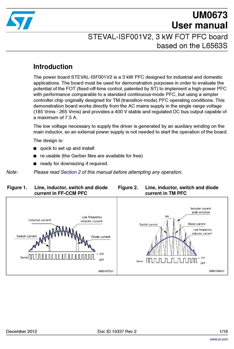
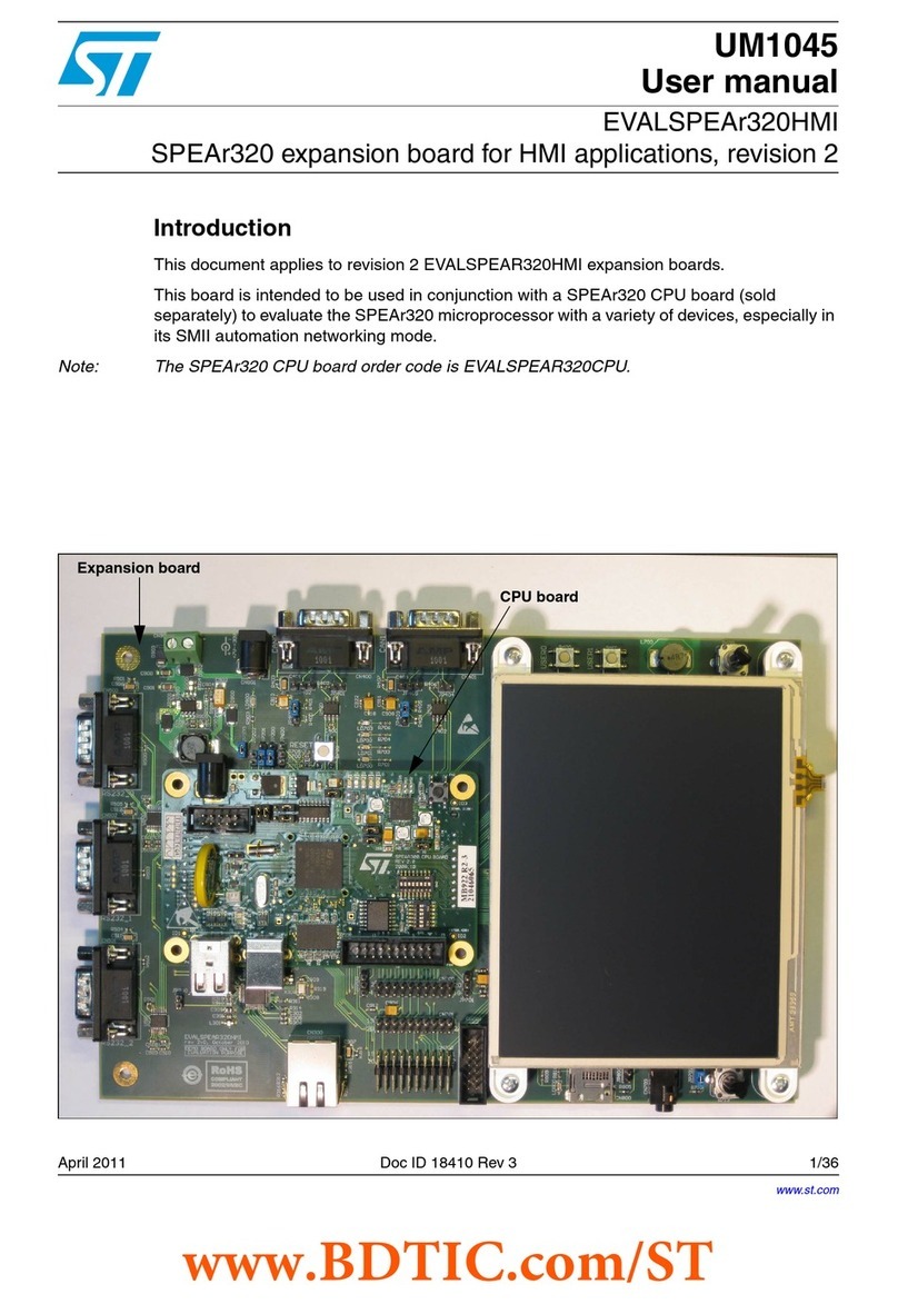
ST STSW-L9026-Y0 User manual
Other ST Computer Hardware manuals
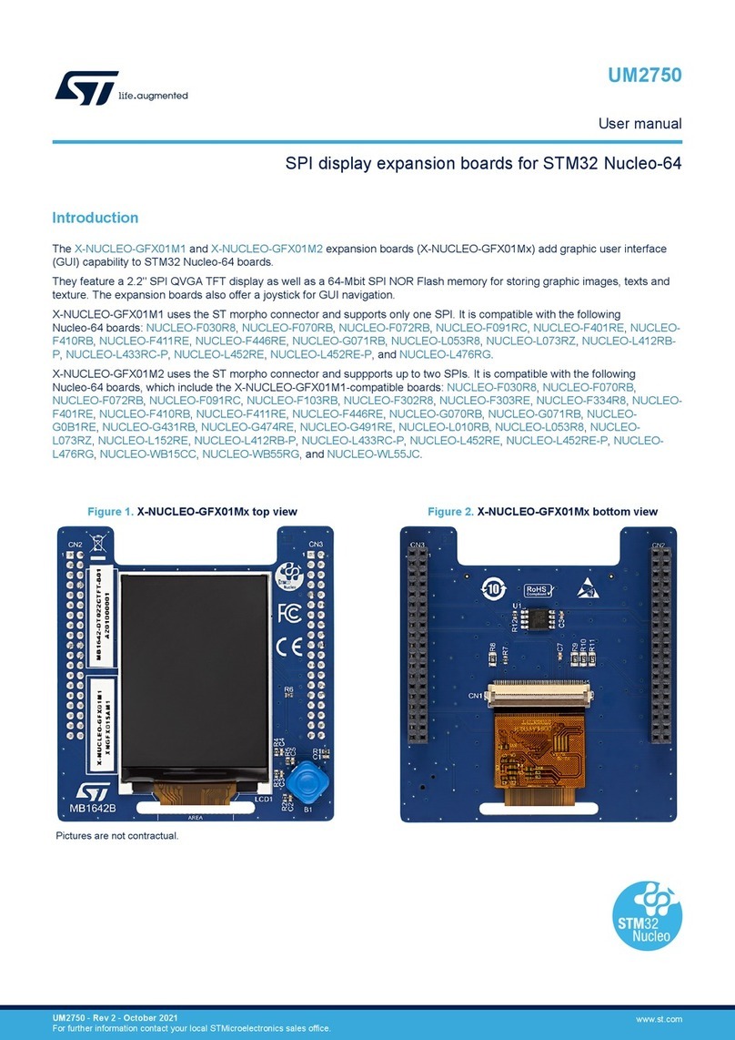
ST
ST X-NUCLEO-GFX01M Series User manual
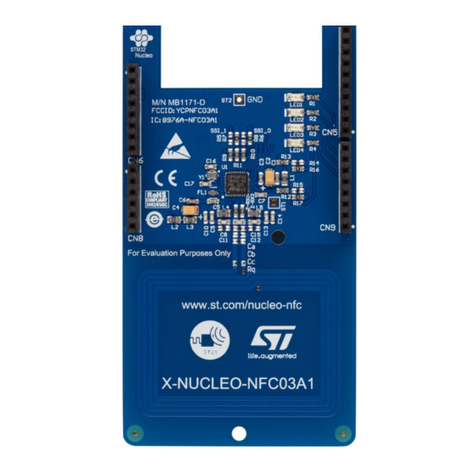
ST
ST X-NUCLEO-NFC03A1 Parts list manual
ST
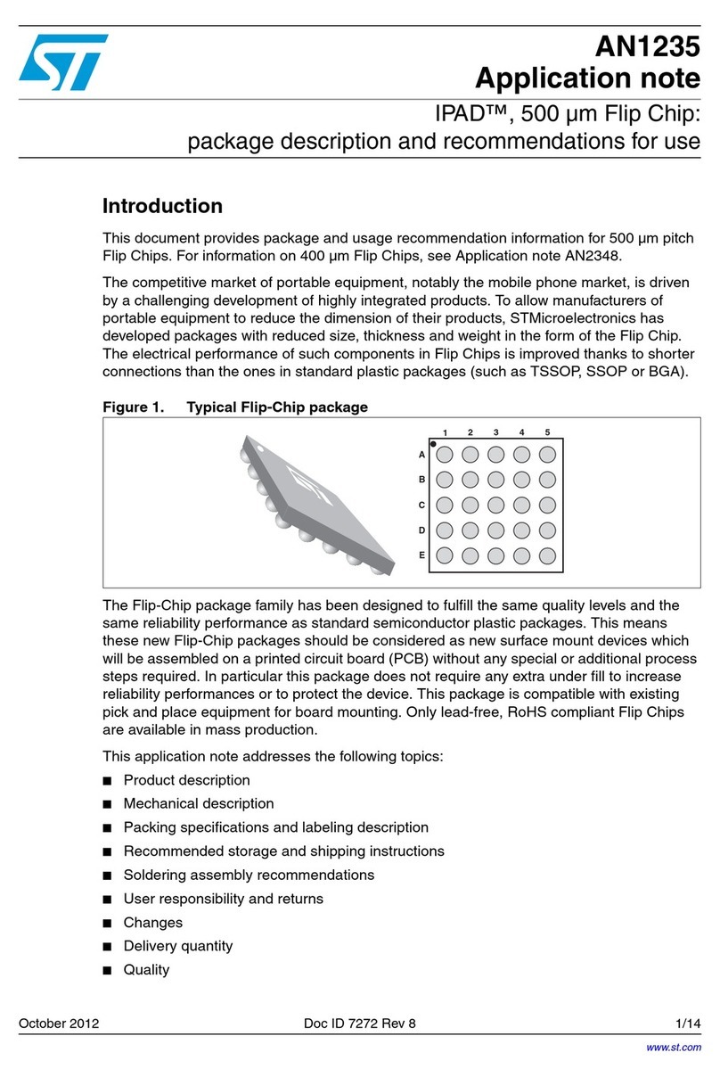
ST AN1235 Installation and operating instructions
ST
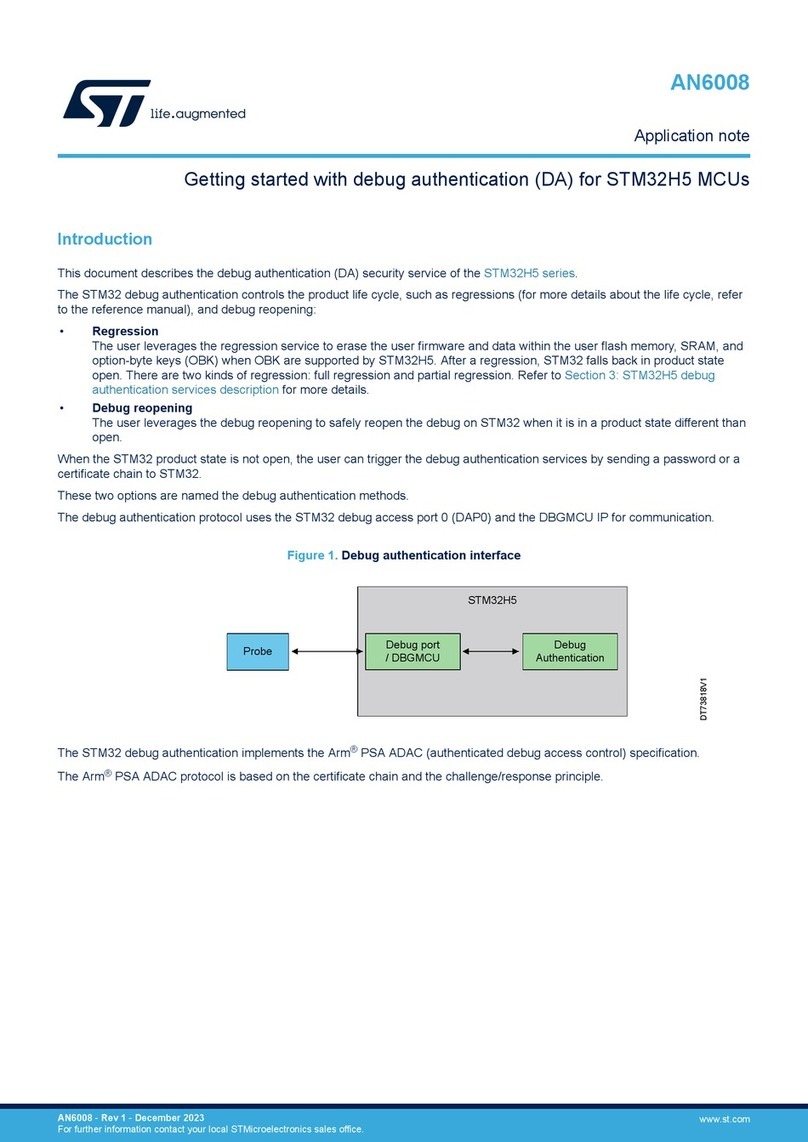
ST STM32H5 User manual
ST
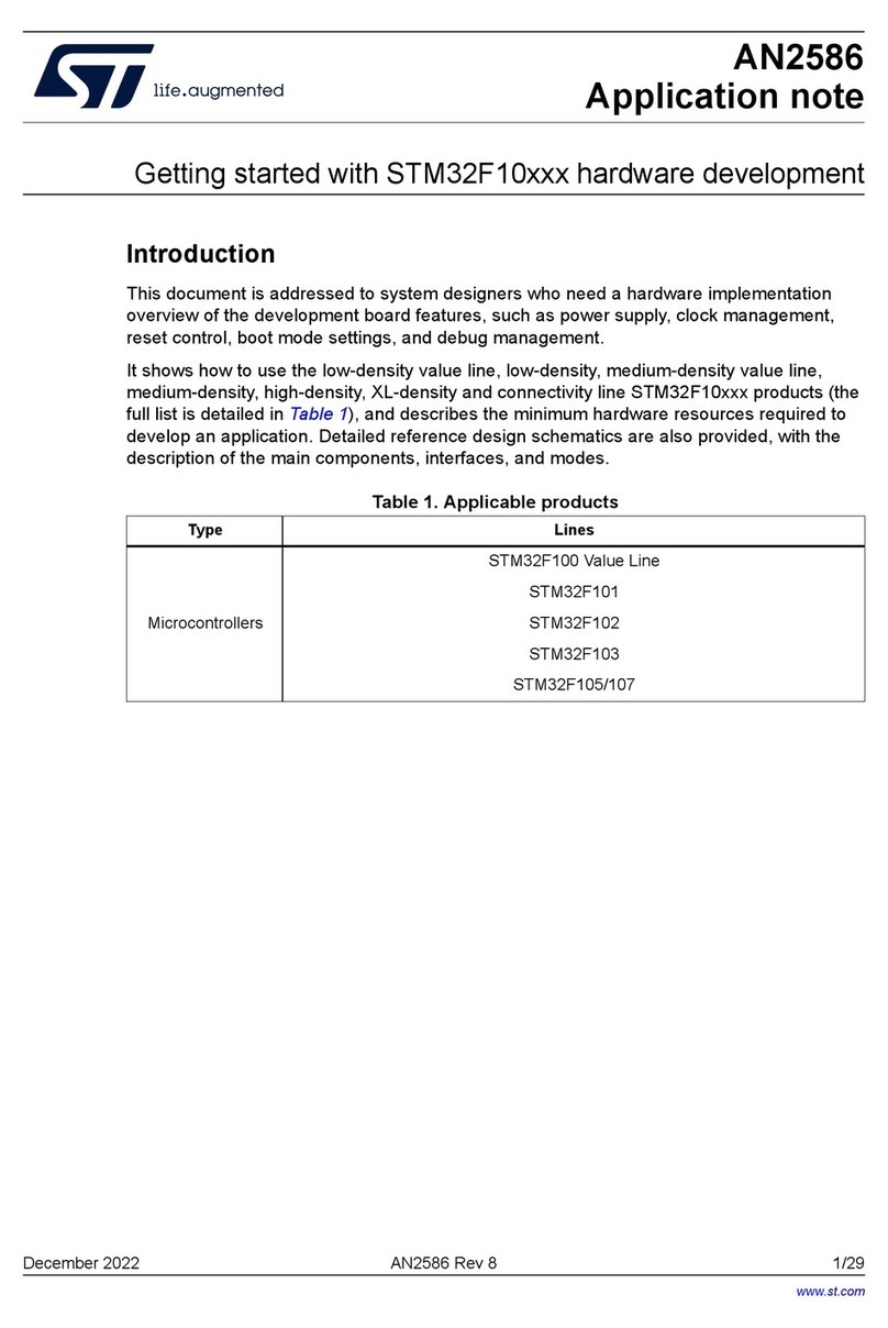
ST STM32F10 Series Installation and operating instructions
ST
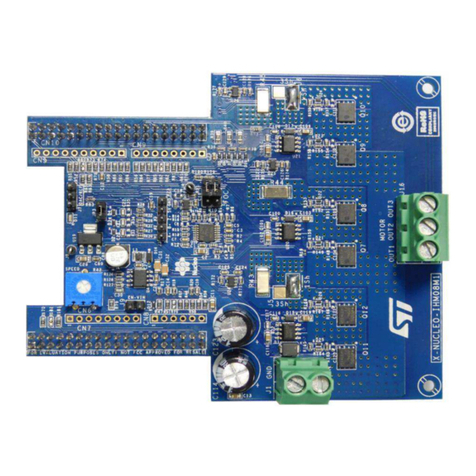
ST X-NUCLEO-IHM08M1 User manual
ST
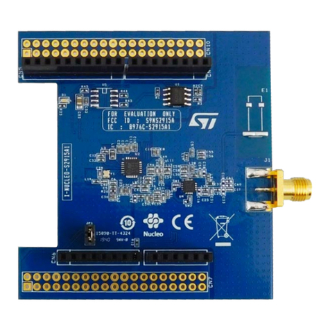
ST X-NUCLEO-S2915A1 User manual
ST
ST STM32Cube User manual
ST
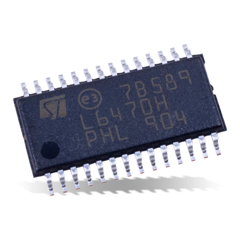
ST L6470H User manual

ST
ST X-NUCLEO-GNSS2A1 User manual
ST
ST STEVAL-OET005 User manual
ST
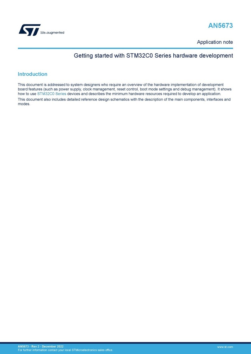
ST STM32C0 Series User manual

ST
ST STM32Cube User manual
ST
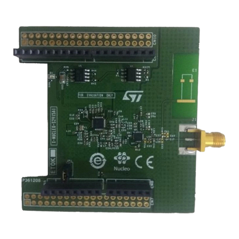
ST X-NUCLEO-S915A1 User manual

ST
ST STLINK-V3PWR User manual
ST
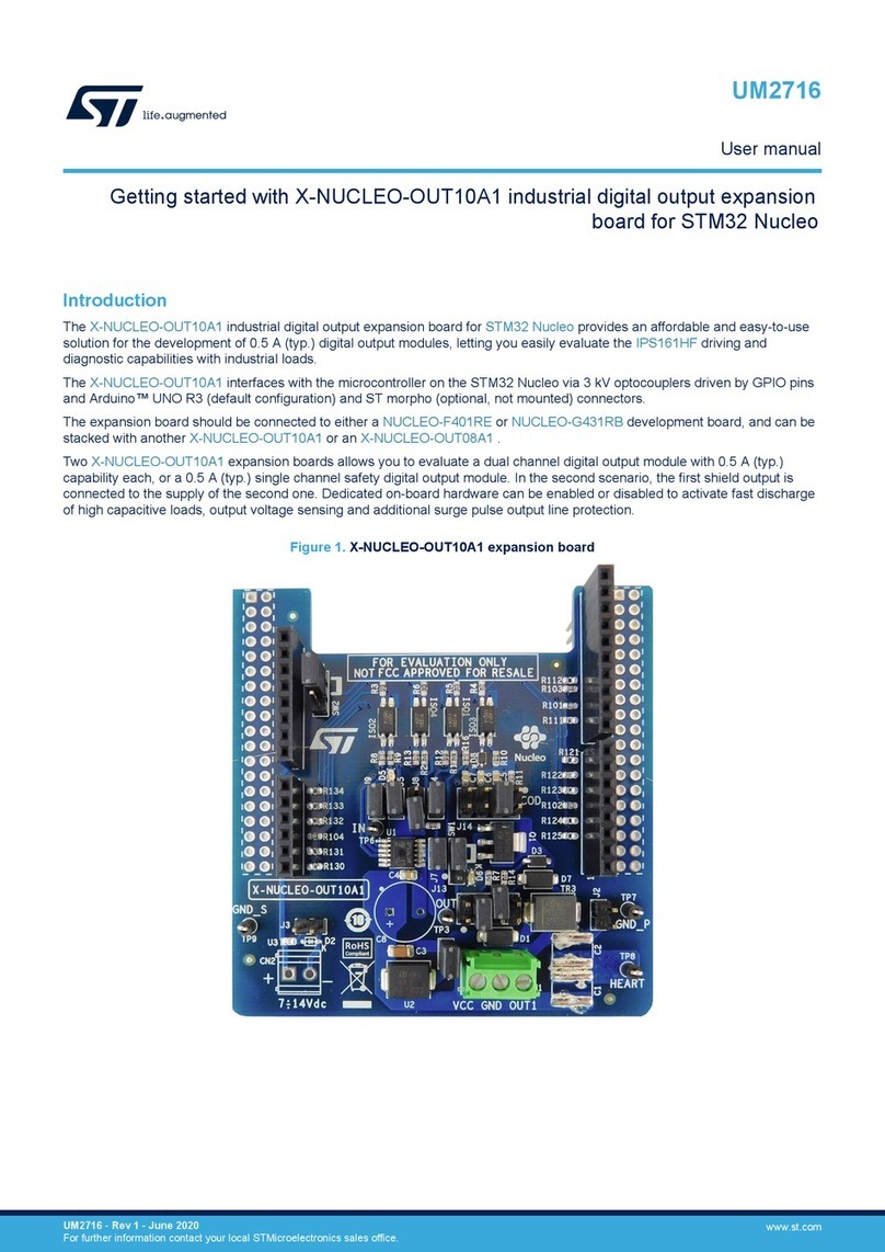
ST X-NUCLEO-OUT10A1 User manual
ST
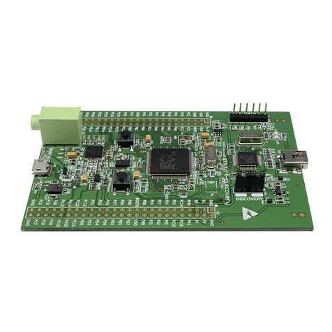
ST STM32F4 Series User manual
ST
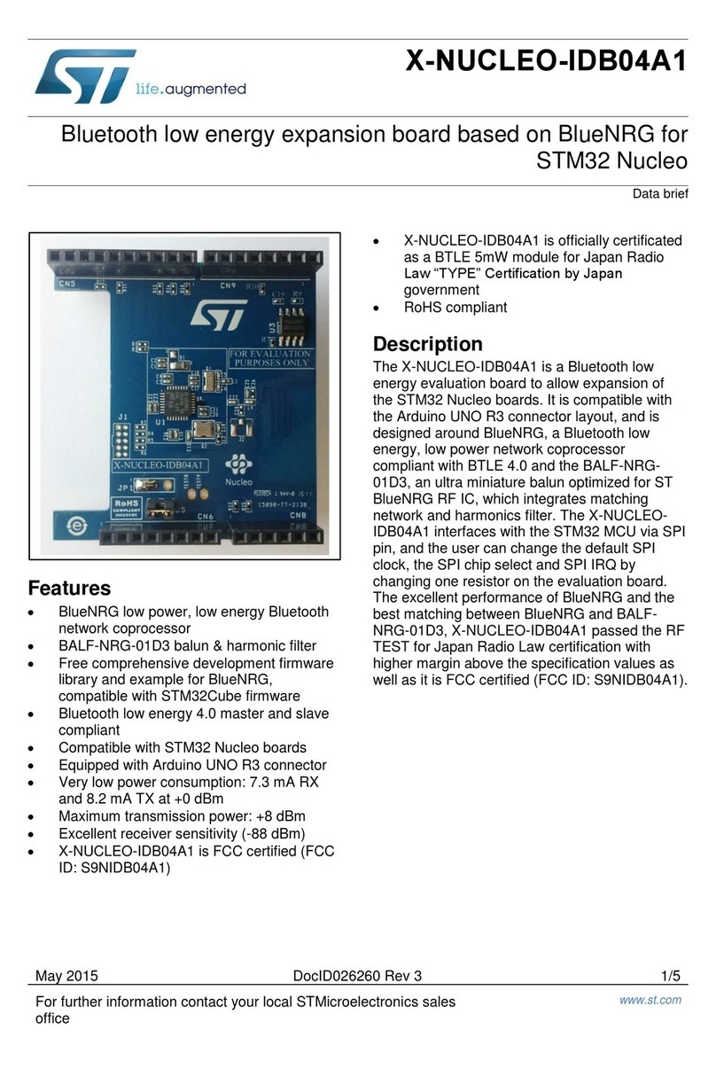
ST X-NUCLEO-IDB04A1 User manual
ST
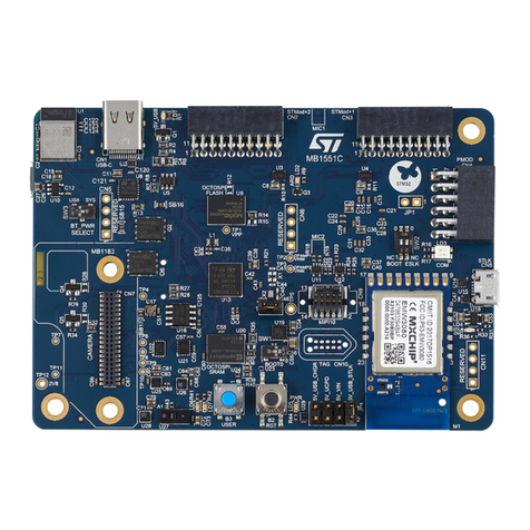
ST STM32U575 Series Installation and operating instructions
ST
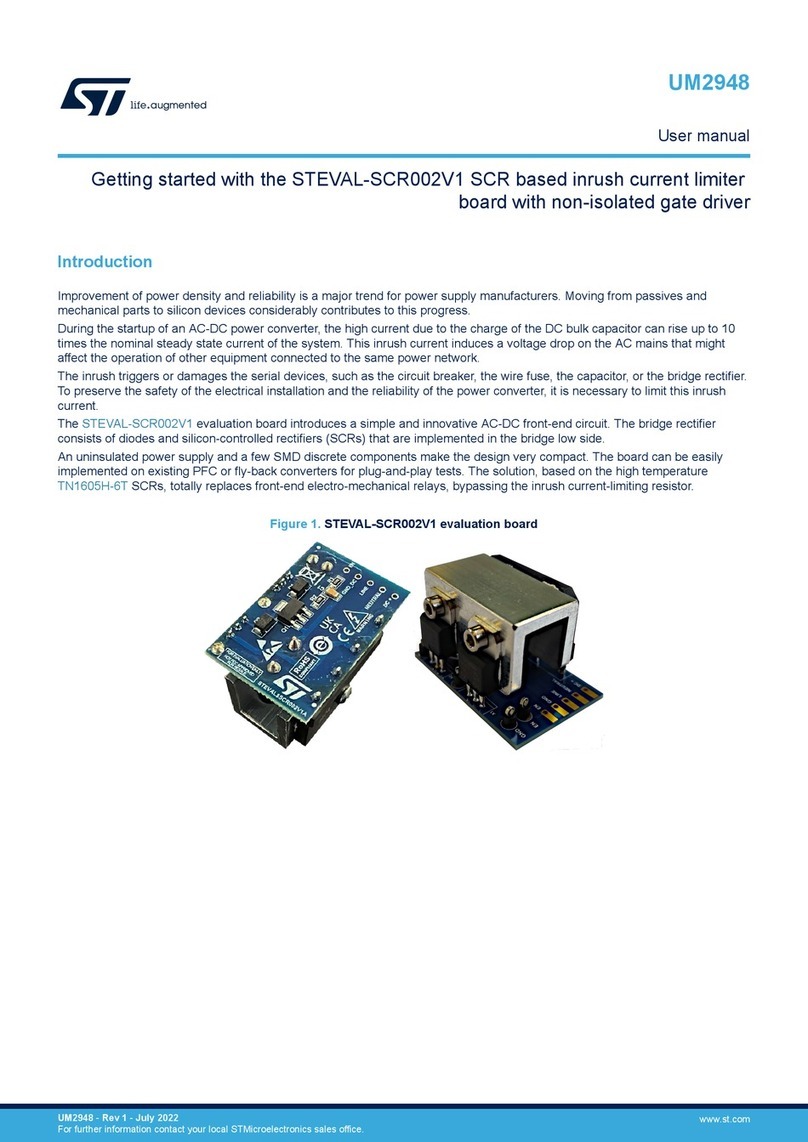
ST STEVAL-SCR002V1 User manual
Popular Computer Hardware manuals by other brands

EMC2
EMC2 VNX Series Hardware Information Guide

Panasonic
Panasonic DV0PM20105 Operation manual

Mitsubishi Electric
Mitsubishi Electric Q81BD-J61BT11 user manual

Gigabyte
Gigabyte B660M DS3H AX DDR4 user manual

Raidon
Raidon iT2300 Quick installation guide

National Instruments
National Instruments PXI-8186 user manual

Intel
Intel AXXRMFBU4 Quick installation user's guide

Kontron
Kontron DIMM-PC/MD product manual

STEINWAY LYNGDORF
STEINWAY LYNGDORF SP-1 installation manual

Advantech
Advantech ASMB-935 Series user manual

Jupiter
Jupiter RAM PACK instructions

Measurement Computing
Measurement Computing CIO-EXP-RTD16 user manual

