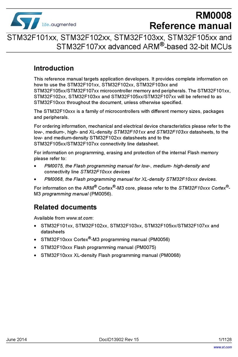
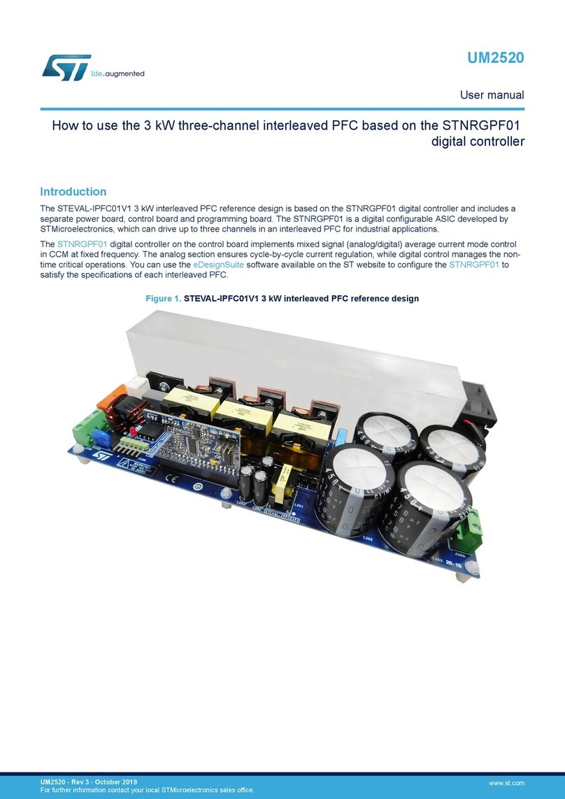
ST STM32F101xx series User manual

January 2011 Doc ID 13902 Rev 12 1/1096
RM0008
Reference manual
STM32F101xx, STM32F102xx, STM32F103xx, STM32F105xx
and STM32F107xx advanced ARM-based 32-bit MCUs
Introduction
This reference manual targets application developers. It provides complete information on
how to use the STM32F101xx, STM32F102xx, STM32F103xx and
STM32F105xx/STM32F107xx microcontroller memory and peripherals. The STM32F101xx,
STM32F102xx, STM32F103xx and STM32F105xx/STM32F107xx will be referred to as
STM32F10xxx throughout the document, unless otherwise specified.
The STM32F10xxx is a family of microcontrollers with different memory sizes, packages and
peripherals.
For ordering information, mechanical and electrical device characteristics please refer to the
low-, medium-, high- and XL-density STM32F101xx and STM32F103xx datasheets, to the
low- and medium-density STM32F102xx datasheets and to the
STM32F105xx/STM32F107xx connectivity line datasheet.
For information on programming, erasing and protection of the internal Flash memory
please refer to:
●RM0042, the Flash programming manual for low-, medium- high-density and
connectivity line STM32F10xxx devices
●PM0068, the Flash programming manual for XL-density STM32F10xxx devices.
For information on the ARM Cortex™-M3 core, please refer to the STM32F10xxx Cortex™-
M3 programming manual (PM0056).
Related documents
Available from www.st.com:
■
STM32F101xx, STM32F102xx, STM32F103xx, STM32F105xx/STM32F107xx and
datasheets
■
STM32F10xxx Cortex™-M3 programming manual (PM0056)
■
STM32F10xxx Flash programming manual (PM0042)
■
STM32F10xxx XL-density Flash programming manual (PM0068)
www.st.com

Contents RM0008
2/1096 Doc ID 13902 Rev 12
Contents
1 Overview of the manual . . . . . . . . . . . . . . . . . . . . . . . . . . . . . . . . . . . . . 40
2 Documentation conventions . . . . . . . . . . . . . . . . . . . . . . . . . . . . . . . . . 46
2.1 List of abbreviations for registers . . . . . . . . . . . . . . . . . . . . . . . . . . . . . . . 46
2.2 Glossary . . . . . . . . . . . . . . . . . . . . . . . . . . . . . . . . . . . . . . . . . . . . . . . . . . 46
2.3 Peripheral availability . . . . . . . . . . . . . . . . . . . . . . . . . . . . . . . . . . . . . . . . 46
3 Memory and bus architecture . . . . . . . . . . . . . . . . . . . . . . . . . . . . . . . . 47
3.1 System architecture . . . . . . . . . . . . . . . . . . . . . . . . . . . . . . . . . . . . . . . . . 47
3.2 Memory organization . . . . . . . . . . . . . . . . . . . . . . . . . . . . . . . . . . . . . . . . 49
3.3 Memory map . . . . . . . . . . . . . . . . . . . . . . . . . . . . . . . . . . . . . . . . . . . . . . 50
3.3.1 Embedded SRAM . . . . . . . . . . . . . . . . . . . . . . . . . . . . . . . . . . . . . . . . . 53
3.3.2 Bit banding . . . . . . . . . . . . . . . . . . . . . . . . . . . . . . . . . . . . . . . . . . . . . . . 53
3.3.3 Embedded Flash memory . . . . . . . . . . . . . . . . . . . . . . . . . . . . . . . . . . . 54
3.4 Boot configuration . . . . . . . . . . . . . . . . . . . . . . . . . . . . . . . . . . . . . . . . . . 60
4 CRC calculation unit . . . . . . . . . . . . . . . . . . . . . . . . . . . . . . . . . . . . . . . . 62
4.1 CRC introduction . . . . . . . . . . . . . . . . . . . . . . . . . . . . . . . . . . . . . . . . . . . 62
4.2 CRC main features . . . . . . . . . . . . . . . . . . . . . . . . . . . . . . . . . . . . . . . . . . 62
4.3 CRC functional description . . . . . . . . . . . . . . . . . . . . . . . . . . . . . . . . . . . . 63
4.4 CRC registers . . . . . . . . . . . . . . . . . . . . . . . . . . . . . . . . . . . . . . . . . . . . . . 63
4.4.1 Data register (CRC_DR) . . . . . . . . . . . . . . . . . . . . . . . . . . . . . . . . . . . . 63
4.4.2 Independent data register (CRC_IDR) . . . . . . . . . . . . . . . . . . . . . . . . . 63
4.4.3 Control register (CRC_CR) . . . . . . . . . . . . . . . . . . . . . . . . . . . . . . . . . . 64
4.4.4 CRC register map . . . . . . . . . . . . . . . . . . . . . . . . . . . . . . . . . . . . . . . . . 64
5 Power control (PWR) . . . . . . . . . . . . . . . . . . . . . . . . . . . . . . . . . . . . . . . . 65
5.1 Power supplies . . . . . . . . . . . . . . . . . . . . . . . . . . . . . . . . . . . . . . . . . . . . . 65
5.1.1 Independent A/D and D/A converter supply and reference voltage . . . . 66
5.1.2 Battery backup domain . . . . . . . . . . . . . . . . . . . . . . . . . . . . . . . . . . . . . 67
5.1.3 Voltage regulator . . . . . . . . . . . . . . . . . . . . . . . . . . . . . . . . . . . . . . . . . . 68
5.2 Power supply supervisor . . . . . . . . . . . . . . . . . . . . . . . . . . . . . . . . . . . . . 68
5.2.1 Power on reset (POR)/power down reset (PDR) . . . . . . . . . . . . . . . . . . 68

RM0008 Contents
Doc ID 13902 Rev 12 3/1096
5.2.2 Programmable voltage detector (PVD) . . . . . . . . . . . . . . . . . . . . . . . . . 68
5.3 Low-power modes . . . . . . . . . . . . . . . . . . . . . . . . . . . . . . . . . . . . . . . . . . 70
5.3.1 Slowing down system clocks . . . . . . . . . . . . . . . . . . . . . . . . . . . . . . . . . 70
5.3.2 Peripheral clock gating . . . . . . . . . . . . . . . . . . . . . . . . . . . . . . . . . . . . . . 71
5.3.3 Sleep mode . . . . . . . . . . . . . . . . . . . . . . . . . . . . . . . . . . . . . . . . . . . . . . 71
5.3.4 Stop mode . . . . . . . . . . . . . . . . . . . . . . . . . . . . . . . . . . . . . . . . . . . . . . . 72
5.3.5 Standby mode . . . . . . . . . . . . . . . . . . . . . . . . . . . . . . . . . . . . . . . . . . . . 73
5.3.6 Auto-wakeup (AWU) from low-power mode . . . . . . . . . . . . . . . . . . . . . . 75
5.4 Power control registers . . . . . . . . . . . . . . . . . . . . . . . . . . . . . . . . . . . . . . . 75
5.4.1 Power control register (PWR_CR) . . . . . . . . . . . . . . . . . . . . . . . . . . . . . 75
5.4.2 Power control/status register (PWR_CSR) . . . . . . . . . . . . . . . . . . . . . . 77
5.4.3 PWR register map . . . . . . . . . . . . . . . . . . . . . . . . . . . . . . . . . . . . . . . . . 78
6 Backup registers (BKP) . . . . . . . . . . . . . . . . . . . . . . . . . . . . . . . . . . . . . 79
6.1 BKP introduction . . . . . . . . . . . . . . . . . . . . . . . . . . . . . . . . . . . . . . . . . . . . 79
6.2 BKP main features . . . . . . . . . . . . . . . . . . . . . . . . . . . . . . . . . . . . . . . . . . 79
6.3 BKP functional description . . . . . . . . . . . . . . . . . . . . . . . . . . . . . . . . . . . . 80
6.3.1 Tamper detection . . . . . . . . . . . . . . . . . . . . . . . . . . . . . . . . . . . . . . . . . . 80
6.3.2 RTC calibration . . . . . . . . . . . . . . . . . . . . . . . . . . . . . . . . . . . . . . . . . . . 80
6.4 BKP registers . . . . . . . . . . . . . . . . . . . . . . . . . . . . . . . . . . . . . . . . . . . . . . 81
6.4.1 Backup data register x (BKP_DRx) (x = 1 ..42) . . . . . . . . . . . . . . . . . . . 81
6.4.2 RTC clock calibration register (BKP_RTCCR) . . . . . . . . . . . . . . . . . . . . 81
6.4.3 Backup control register (BKP_CR) . . . . . . . . . . . . . . . . . . . . . . . . . . . . 82
6.4.4 Backup control/status register (BKP_CSR) . . . . . . . . . . . . . . . . . . . . . . 82
6.4.5 BKP register map . . . . . . . . . . . . . . . . . . . . . . . . . . . . . . . . . . . . . . . . . . 83
7 Low-, medium-, high- and XL-density reset and clock
control (RCC) . . . . . . . . . . . . . . . . . . . . . . . . . . . . . . . . . . . . . . . . . . . . . . 87
7.1 Reset . . . . . . . . . . . . . . . . . . . . . . . . . . . . . . . . . . . . . . . . . . . . . . . . . . . . 87
7.1.1 System reset . . . . . . . . . . . . . . . . . . . . . . . . . . . . . . . . . . . . . . . . . . . . . 87
7.1.2 Power reset . . . . . . . . . . . . . . . . . . . . . . . . . . . . . . . . . . . . . . . . . . . . . . 88
7.1.3 Backup domain reset . . . . . . . . . . . . . . . . . . . . . . . . . . . . . . . . . . . . . . . 88
7.2 Clocks . . . . . . . . . . . . . . . . . . . . . . . . . . . . . . . . . . . . . . . . . . . . . . . . . . . . 89
7.2.1 HSE clock . . . . . . . . . . . . . . . . . . . . . . . . . . . . . . . . . . . . . . . . . . . . . . . 91
7.2.2 HSI clock . . . . . . . . . . . . . . . . . . . . . . . . . . . . . . . . . . . . . . . . . . . . . . . . 92
7.2.3 PLL . . . . . . . . . . . . . . . . . . . . . . . . . . . . . . . . . . . . . . . . . . . . . . . . . . . . 92

Contents RM0008
4/1096 Doc ID 13902 Rev 12
7.2.4 LSE clock . . . . . . . . . . . . . . . . . . . . . . . . . . . . . . . . . . . . . . . . . . . . . . . . 93
7.2.5 LSI clock . . . . . . . . . . . . . . . . . . . . . . . . . . . . . . . . . . . . . . . . . . . . . . . . 93
7.2.6 System clock (SYSCLK) selection . . . . . . . . . . . . . . . . . . . . . . . . . . . . . 94
7.2.7 Clock security system (CSS) . . . . . . . . . . . . . . . . . . . . . . . . . . . . . . . . . 94
7.2.8 RTC clock . . . . . . . . . . . . . . . . . . . . . . . . . . . . . . . . . . . . . . . . . . . . . . . 94
7.2.9 Watchdog clock . . . . . . . . . . . . . . . . . . . . . . . . . . . . . . . . . . . . . . . . . . . 95
7.2.10 Clock-out capability . . . . . . . . . . . . . . . . . . . . . . . . . . . . . . . . . . . . . . . . 95
7.3 RCC registers . . . . . . . . . . . . . . . . . . . . . . . . . . . . . . . . . . . . . . . . . . . . . . 96
7.3.1 Clock control register (RCC_CR) . . . . . . . . . . . . . . . . . . . . . . . . . . . . . . 96
7.3.2 Clock configuration register (RCC_CFGR) . . . . . . . . . . . . . . . . . . . . . . 98
7.3.3 Clock interrupt register (RCC_CIR) . . . . . . . . . . . . . . . . . . . . . . . . . . . 101
7.3.4 APB2 peripheral reset register (RCC_APB2RSTR) . . . . . . . . . . . . . . 103
7.3.5 APB1 peripheral reset register (RCC_APB1RSTR) . . . . . . . . . . . . . . 106
7.3.6 AHB peripheral clock enable register (RCC_AHBENR) . . . . . . . . . . . 108
7.3.7 APB2 peripheral clock enable register (RCC_APB2ENR) . . . . . . . . . . 109
7.3.8 APB1 peripheral clock enable register (RCC_APB1ENR) . . . . . . . . . . 111
7.3.9 Backup domain control register (RCC_BDCR) . . . . . . . . . . . . . . . . . . 115
7.3.10 Control/status register (RCC_CSR) . . . . . . . . . . . . . . . . . . . . . . . . . . . 117
7.3.11 RCC register map . . . . . . . . . . . . . . . . . . . . . . . . . . . . . . . . . . . . . . . . 119
8 Connectivity line devices: reset and clock control (RCC) . . . . . . . . . 120
8.1 Reset . . . . . . . . . . . . . . . . . . . . . . . . . . . . . . . . . . . . . . . . . . . . . . . . . . . 120
8.1.1 System reset . . . . . . . . . . . . . . . . . . . . . . . . . . . . . . . . . . . . . . . . . . . . 120
8.1.2 Power reset . . . . . . . . . . . . . . . . . . . . . . . . . . . . . . . . . . . . . . . . . . . . . 121
8.1.3 Backup domain reset . . . . . . . . . . . . . . . . . . . . . . . . . . . . . . . . . . . . . . 122
8.2 Clocks . . . . . . . . . . . . . . . . . . . . . . . . . . . . . . . . . . . . . . . . . . . . . . . . . . . 122
8.2.1 HSE clock . . . . . . . . . . . . . . . . . . . . . . . . . . . . . . . . . . . . . . . . . . . . . . 124
8.2.2 HSI clock . . . . . . . . . . . . . . . . . . . . . . . . . . . . . . . . . . . . . . . . . . . . . . . 125
8.2.3 PLLs . . . . . . . . . . . . . . . . . . . . . . . . . . . . . . . . . . . . . . . . . . . . . . . . . . . 126
8.2.4 LSE clock . . . . . . . . . . . . . . . . . . . . . . . . . . . . . . . . . . . . . . . . . . . . . . . 126
8.2.5 LSI clock . . . . . . . . . . . . . . . . . . . . . . . . . . . . . . . . . . . . . . . . . . . . . . . 127
8.2.6 System clock (SYSCLK) selection . . . . . . . . . . . . . . . . . . . . . . . . . . . . 127
8.2.7 Clock security system (CSS) . . . . . . . . . . . . . . . . . . . . . . . . . . . . . . . . 128
8.2.8 RTC clock . . . . . . . . . . . . . . . . . . . . . . . . . . . . . . . . . . . . . . . . . . . . . . 128
8.2.9 Watchdog clock . . . . . . . . . . . . . . . . . . . . . . . . . . . . . . . . . . . . . . . . . . 128
8.2.10 Clock-out capability . . . . . . . . . . . . . . . . . . . . . . . . . . . . . . . . . . . . . . . 129
8.3 RCC registers . . . . . . . . . . . . . . . . . . . . . . . . . . . . . . . . . . . . . . . . . . . . . 129

RM0008 Contents
Doc ID 13902 Rev 12 5/1096
8.3.1 Clock control register (RCC_CR) . . . . . . . . . . . . . . . . . . . . . . . . . . . . . 129
8.3.2 Clock configuration register (RCC_CFGR) . . . . . . . . . . . . . . . . . . . . . 131
8.3.3 Clock interrupt register (RCC_CIR) . . . . . . . . . . . . . . . . . . . . . . . . . . . 134
8.3.4 APB2 peripheral reset register (RCC_APB2RSTR) . . . . . . . . . . . . . . 137
8.3.5 APB1 peripheral reset register (RCC_APB1RSTR) . . . . . . . . . . . . . . 138
8.3.6 AHB Peripheral Clock enable register (RCC_AHBENR) . . . . . . . . . . . 141
8.3.7 APB2 peripheral clock enable register (RCC_APB2ENR) . . . . . . . . . . 142
8.3.8 APB1 peripheral clock enable register (RCC_APB1ENR) . . . . . . . . . . 144
8.3.9 Backup domain control register (RCC_BDCR) . . . . . . . . . . . . . . . . . . 146
8.3.10 Control/status register (RCC_CSR) . . . . . . . . . . . . . . . . . . . . . . . . . . . 148
8.3.11 AHB peripheral clock reset register (RCC_AHBRSTR) . . . . . . . . . . . . 149
8.3.12 Clock configuration register2 (RCC_CFGR2) . . . . . . . . . . . . . . . . . . . 150
8.3.13 RCC register map . . . . . . . . . . . . . . . . . . . . . . . . . . . . . . . . . . . . . . . . 152
9 General-purpose and alternate-function I/Os (GPIOs and AFIOs) . . 154
9.1 GPIO functional description . . . . . . . . . . . . . . . . . . . . . . . . . . . . . . . . . . 154
9.1.1 General-purpose I/O (GPIO) . . . . . . . . . . . . . . . . . . . . . . . . . . . . . . . . 156
9.1.2 Atomic bit set or reset . . . . . . . . . . . . . . . . . . . . . . . . . . . . . . . . . . . . . 156
9.1.3 External interrupt/wakeup lines . . . . . . . . . . . . . . . . . . . . . . . . . . . . . . 157
9.1.4 Alternate functions (AF) . . . . . . . . . . . . . . . . . . . . . . . . . . . . . . . . . . . . 157
9.1.5 Software remapping of I/O alternate functions . . . . . . . . . . . . . . . . . . 157
9.1.6 GPIO locking mechanism . . . . . . . . . . . . . . . . . . . . . . . . . . . . . . . . . . 157
9.1.7 Input configuration . . . . . . . . . . . . . . . . . . . . . . . . . . . . . . . . . . . . . . . . 158
9.1.8 Output configuration . . . . . . . . . . . . . . . . . . . . . . . . . . . . . . . . . . . . . . 158
9.1.9 Alternate function configuration . . . . . . . . . . . . . . . . . . . . . . . . . . . . . . 159
9.1.10 Analog configuration . . . . . . . . . . . . . . . . . . . . . . . . . . . . . . . . . . . . . . 160
9.1.11 GPIO configurations for device peripherals . . . . . . . . . . . . . . . . . . . . . 161
9.2 GPIO registers . . . . . . . . . . . . . . . . . . . . . . . . . . . . . . . . . . . . . . . . . . . . 165
9.2.1 Port configuration register low (GPIOx_CRL) (x=A..G) . . . . . . . . . . . . 165
9.2.2 Port configuration register high (GPIOx_CRH) (x=A..G) . . . . . . . . . . . 166
9.2.3 Port input data register (GPIOx_IDR) (x=A..G) . . . . . . . . . . . . . . . . . . 166
9.2.4 Port output data register (GPIOx_ODR) (x=A..G) . . . . . . . . . . . . . . . . 167
9.2.5 Port bit set/reset register (GPIOx_BSRR) (x=A..G) . . . . . . . . . . . . . . . 167
9.2.6 Port bit reset register (GPIOx_BRR) (x=A..G) . . . . . . . . . . . . . . . . . . . 168
9.2.7 Port configuration lock register (GPIOx_LCKR) (x=A..G) . . . . . . . . . . 168
9.3 Alternate function I/O and debug configuration (AFIO) . . . . . . . . . . . . . 169
9.3.1 Using OSC32_IN/OSC32_OUT pins as GPIO ports PC14/PC15 . . . . 169

Contents RM0008
6/1096 Doc ID 13902 Rev 12
9.3.2 Using OSC_IN/OSC_OUT pins as GPIO ports PD0/PD1 . . . . . . . . . . 169
9.3.3 CAN1 alternate function remapping . . . . . . . . . . . . . . . . . . . . . . . . . . . 170
9.3.4 CAN2 alternate function remapping . . . . . . . . . . . . . . . . . . . . . . . . . . . 170
9.3.5 JTAG/SWD alternate function remapping . . . . . . . . . . . . . . . . . . . . . . 170
9.3.6 ADC alternate function remapping . . . . . . . . . . . . . . . . . . . . . . . . . . . . 171
9.3.7 Timer alternate function remapping . . . . . . . . . . . . . . . . . . . . . . . . . . . 172
9.3.8 USART alternate function remapping . . . . . . . . . . . . . . . . . . . . . . . . . 174
9.3.9 I2C1 alternate function remapping . . . . . . . . . . . . . . . . . . . . . . . . . . . . 175
9.3.10 SPI1 alternate function remapping . . . . . . . . . . . . . . . . . . . . . . . . . . . 175
9.3.11 SPI3/I2S3 alternate function remapping . . . . . . . . . . . . . . . . . . . . . . . 175
9.3.12 Ethernet alternate function remapping . . . . . . . . . . . . . . . . . . . . . . . . 175
9.4 AFIO registers . . . . . . . . . . . . . . . . . . . . . . . . . . . . . . . . . . . . . . . . . . . . 176
9.4.1 Event control register (AFIO_EVCR) . . . . . . . . . . . . . . . . . . . . . . . . . . 177
9.4.2 AF remap and debug I/O configuration register (AFIO_MAPR) . . . . . . 178
9.4.3 External interrupt configuration register 1 (AFIO_EXTICR1) . . . . . . . . 184
9.4.4 External interrupt configuration register 2 (AFIO_EXTICR2) . . . . . . . . 184
9.4.5 External interrupt configuration register 3 (AFIO_EXTICR3) . . . . . . . . 185
9.4.6 External interrupt configuration register 4 (AFIO_EXTICR4) . . . . . . . . 185
9.4.7 AF remap and debug I/O configuration register2 (AFIO_MAPR2) . . . . 186
9.5 GPIO and AFIO register maps . . . . . . . . . . . . . . . . . . . . . . . . . . . . . . . . 187
10 Interrupts and events . . . . . . . . . . . . . . . . . . . . . . . . . . . . . . . . . . . . . . 189
10.1 Nested vectored interrupt controller (NVIC) . . . . . . . . . . . . . . . . . . . . . . 189
10.1.1 SysTick calibration value register . . . . . . . . . . . . . . . . . . . . . . . . . . . . 189
10.1.2 Interrupt and exception vectors . . . . . . . . . . . . . . . . . . . . . . . . . . . . . . 189
10.2 External interrupt/event controller (EXTI) . . . . . . . . . . . . . . . . . . . . . . . . 197
10.2.1 Main features . . . . . . . . . . . . . . . . . . . . . . . . . . . . . . . . . . . . . . . . . . . . 197
10.2.2 Block diagram . . . . . . . . . . . . . . . . . . . . . . . . . . . . . . . . . . . . . . . . . . . 197
10.2.3 Wakeup event management . . . . . . . . . . . . . . . . . . . . . . . . . . . . . . . . 198
10.2.4 Functional description . . . . . . . . . . . . . . . . . . . . . . . . . . . . . . . . . . . . . 198
10.2.5 External interrupt/event line mapping . . . . . . . . . . . . . . . . . . . . . . . . . 199
10.3 EXTI registers . . . . . . . . . . . . . . . . . . . . . . . . . . . . . . . . . . . . . . . . . . . . . 201
10.3.1 Interrupt mask register (EXTI_IMR) . . . . . . . . . . . . . . . . . . . . . . . . . . . 201
10.3.2 Event mask register (EXTI_EMR) . . . . . . . . . . . . . . . . . . . . . . . . . . . . 201
10.3.3 Rising trigger selection register (EXTI_RTSR) . . . . . . . . . . . . . . . . . . 202
10.3.4 Falling trigger selection register (EXTI_FTSR) . . . . . . . . . . . . . . . . . . 202
10.3.5 Software interrupt event register (EXTI_SWIER) . . . . . . . . . . . . . . . . . 203

RM0008 Contents
Doc ID 13902 Rev 12 7/1096
10.3.6 Pending register (EXTI_PR) . . . . . . . . . . . . . . . . . . . . . . . . . . . . . . . . 203
10.3.7 EXTI register map . . . . . . . . . . . . . . . . . . . . . . . . . . . . . . . . . . . . . . . . 204
11 Analog-to-digital converter (ADC) . . . . . . . . . . . . . . . . . . . . . . . . . . . . 205
11.1 ADC introduction . . . . . . . . . . . . . . . . . . . . . . . . . . . . . . . . . . . . . . . . . . 205
11.2 ADC main features . . . . . . . . . . . . . . . . . . . . . . . . . . . . . . . . . . . . . . . . . 206
11.3 ADC functional description . . . . . . . . . . . . . . . . . . . . . . . . . . . . . . . . . . . 206
11.3.1 ADC on-off control . . . . . . . . . . . . . . . . . . . . . . . . . . . . . . . . . . . . . . . . 209
11.3.2 ADC clock . . . . . . . . . . . . . . . . . . . . . . . . . . . . . . . . . . . . . . . . . . . . . . 209
11.3.3 Channel selection . . . . . . . . . . . . . . . . . . . . . . . . . . . . . . . . . . . . . . . . 209
11.3.4 Single conversion mode . . . . . . . . . . . . . . . . . . . . . . . . . . . . . . . . . . . . 209
11.3.5 Continuous conversion mode . . . . . . . . . . . . . . . . . . . . . . . . . . . . . . . 210
11.3.6 Timing diagram . . . . . . . . . . . . . . . . . . . . . . . . . . . . . . . . . . . . . . . . . . 210
11.3.7 Analog watchdog . . . . . . . . . . . . . . . . . . . . . . . . . . . . . . . . . . . . . . . . . 211
11.3.8 Scan mode . . . . . . . . . . . . . . . . . . . . . . . . . . . . . . . . . . . . . . . . . . . . . . 211
11.3.9 Injected channel management . . . . . . . . . . . . . . . . . . . . . . . . . . . . . . . 212
11.3.10 Discontinuous mode . . . . . . . . . . . . . . . . . . . . . . . . . . . . . . . . . . . . . . 213
11.4 Calibration . . . . . . . . . . . . . . . . . . . . . . . . . . . . . . . . . . . . . . . . . . . . . . . 213
11.5 Data alignment . . . . . . . . . . . . . . . . . . . . . . . . . . . . . . . . . . . . . . . . . . . . 214
11.6 Channel-by-channel programmable sample time . . . . . . . . . . . . . . . . . . 215
11.7 Conversion on external trigger . . . . . . . . . . . . . . . . . . . . . . . . . . . . . . . . 215
11.8 DMA request . . . . . . . . . . . . . . . . . . . . . . . . . . . . . . . . . . . . . . . . . . . . . 217
11.9 Dual ADC mode . . . . . . . . . . . . . . . . . . . . . . . . . . . . . . . . . . . . . . . . . . . 218
11.9.1 Injected simultaneous mode . . . . . . . . . . . . . . . . . . . . . . . . . . . . . . . . 220
11.9.2 Regular simultaneous mode . . . . . . . . . . . . . . . . . . . . . . . . . . . . . . . . 220
11.9.3 Fast interleaved mode . . . . . . . . . . . . . . . . . . . . . . . . . . . . . . . . . . . . . 221
11.9.4 Slow interleaved mode . . . . . . . . . . . . . . . . . . . . . . . . . . . . . . . . . . . . . 221
11.9.5 Alternate trigger mode . . . . . . . . . . . . . . . . . . . . . . . . . . . . . . . . . . . . . 222
11.9.6 Independent mode . . . . . . . . . . . . . . . . . . . . . . . . . . . . . . . . . . . . . . . . 223
11.9.7 Combined regular/injected simultaneous mode . . . . . . . . . . . . . . . . . . 223
11.9.8 Combined regular simultaneous + alternate trigger mode . . . . . . . . . . 223
11.9.9 Combined injected simultaneous + interleaved . . . . . . . . . . . . . . . . . . 224
11.10 Temperature sensor . . . . . . . . . . . . . . . . . . . . . . . . . . . . . . . . . . . . . . . . 225
11.11 ADC interrupts . . . . . . . . . . . . . . . . . . . . . . . . . . . . . . . . . . . . . . . . . . . . 226
11.12 ADC registers . . . . . . . . . . . . . . . . . . . . . . . . . . . . . . . . . . . . . . . . . . . . . 227
11.12.1 ADC status register (ADC_SR) . . . . . . . . . . . . . . . . . . . . . . . . . . . . . . 227

Contents RM0008
8/1096 Doc ID 13902 Rev 12
11.12.2 ADC control register 1 (ADC_CR1) . . . . . . . . . . . . . . . . . . . . . . . . . . . 228
11.12.3 ADC control register 2 (ADC_CR2) . . . . . . . . . . . . . . . . . . . . . . . . . . . 230
11.12.4 ADC sample time register 1 (ADC_SMPR1) . . . . . . . . . . . . . . . . . . . . 234
11.12.5 ADC sample time register 2 (ADC_SMPR2) . . . . . . . . . . . . . . . . . . . . 235
11.12.6 ADC injected channel data offset register x (ADC_JOFRx)(x=1..4) . . 235
11.12.7 ADC watchdog high threshold register (ADC_HTR) . . . . . . . . . . . . . . 236
11.12.8 ADC watchdog low threshold register (ADC_LTR) . . . . . . . . . . . . . . . 236
11.12.9 ADC regular sequence register 1 (ADC_SQR1) . . . . . . . . . . . . . . . . . 237
11.12.10 ADC regular sequence register 2 (ADC_SQR2) . . . . . . . . . . . . . . . . . 238
11.12.11 ADC regular sequence register 3 (ADC_SQR3) . . . . . . . . . . . . . . . . . 239
11.12.12 ADC injected sequence register (ADC_JSQR) . . . . . . . . . . . . . . . . . . 240
11.12.13 ADC injected data register x (ADC_JDRx) (x= 1..4) . . . . . . . . . . . . . . 240
11.12.14 ADC regular data register (ADC_DR) . . . . . . . . . . . . . . . . . . . . . . . . . 241
11.12.15 ADC register map . . . . . . . . . . . . . . . . . . . . . . . . . . . . . . . . . . . . . . . . 241
12 Digital-to-analog converter (DAC) . . . . . . . . . . . . . . . . . . . . . . . . . . . . 243
12.1 DAC introduction . . . . . . . . . . . . . . . . . . . . . . . . . . . . . . . . . . . . . . . . . . 243
12.2 DAC main features . . . . . . . . . . . . . . . . . . . . . . . . . . . . . . . . . . . . . . . . . 243
12.3 DAC functional description . . . . . . . . . . . . . . . . . . . . . . . . . . . . . . . . . . . 245
12.3.1 DAC channel enable . . . . . . . . . . . . . . . . . . . . . . . . . . . . . . . . . . . . . . 245
12.3.2 DAC output buffer enable . . . . . . . . . . . . . . . . . . . . . . . . . . . . . . . . . . . 245
12.3.3 DAC data format . . . . . . . . . . . . . . . . . . . . . . . . . . . . . . . . . . . . . . . . . 245
12.3.4 DAC conversion . . . . . . . . . . . . . . . . . . . . . . . . . . . . . . . . . . . . . . . . . . 246
12.3.5 DAC output voltage . . . . . . . . . . . . . . . . . . . . . . . . . . . . . . . . . . . . . . . 247
12.3.6 DAC trigger selection . . . . . . . . . . . . . . . . . . . . . . . . . . . . . . . . . . . . . . 247
12.3.7 DMA request . . . . . . . . . . . . . . . . . . . . . . . . . . . . . . . . . . . . . . . . . . . . 248
12.3.8 Noise generation . . . . . . . . . . . . . . . . . . . . . . . . . . . . . . . . . . . . . . . . . 248
12.3.9 Triangle-wave generation . . . . . . . . . . . . . . . . . . . . . . . . . . . . . . . . . . . 249
12.4 Dual DAC channel conversion . . . . . . . . . . . . . . . . . . . . . . . . . . . . . . . . 250
12.4.1 Independent trigger without wave generation . . . . . . . . . . . . . . . . . . . 250
12.4.2 Independent trigger with same LFSR generation . . . . . . . . . . . . . . . . 251
12.4.3 Independent trigger with different LFSR generation . . . . . . . . . . . . . . 251
12.4.4 Independent trigger with same triangle generation . . . . . . . . . . . . . . . 251
12.4.5 Independent trigger with different triangle generation . . . . . . . . . . . . . 252
12.4.6 Simultaneous software start . . . . . . . . . . . . . . . . . . . . . . . . . . . . . . . . 252
12.4.7 Simultaneous trigger without wave generation . . . . . . . . . . . . . . . . . . 252
12.4.8 Simultaneous trigger with same LFSR generation . . . . . . . . . . . . . . . 253

RM0008 Contents
Doc ID 13902 Rev 12 9/1096
12.4.9 Simultaneous trigger with different LFSR generation . . . . . . . . . . . . . 253
12.4.10 Simultaneous trigger with same triangle generation . . . . . . . . . . . . . . 253
12.4.11 Simultaneous trigger with different triangle generation . . . . . . . . . . . . 254
12.5 DAC registers . . . . . . . . . . . . . . . . . . . . . . . . . . . . . . . . . . . . . . . . . . . . . 254
12.5.1 DAC control register (DAC_CR) . . . . . . . . . . . . . . . . . . . . . . . . . . . . . . 254
12.5.2 DAC software trigger register (DAC_SWTRIGR) . . . . . . . . . . . . . . . . . 257
12.5.3 DAC channel1 12-bit right-aligned data holding register
(DAC_DHR12R1) . . . . . . . . . . . . . . . . . . . . . . . . . . . . . . . . . . . . . . . . . 258
12.5.4 DAC channel1 12-bit left aligned data holding register
(DAC_DHR12L1) . . . . . . . . . . . . . . . . . . . . . . . . . . . . . . . . . . . . . . . . . 258
12.5.5 DAC channel1 8-bit right aligned data holding register
(DAC_DHR8R1) . . . . . . . . . . . . . . . . . . . . . . . . . . . . . . . . . . . . . . . . . . 258
12.5.6 DAC channel2 12-bit right aligned data holding register
(DAC_DHR12R2) . . . . . . . . . . . . . . . . . . . . . . . . . . . . . . . . . . . . . . . . . 259
12.5.7 DAC channel2 12-bit left aligned data holding register
(DAC_DHR12L2) . . . . . . . . . . . . . . . . . . . . . . . . . . . . . . . . . . . . . . . . . 259
12.5.8 DAC channel2 8-bit right-aligned data holding register
(DAC_DHR8R2) . . . . . . . . . . . . . . . . . . . . . . . . . . . . . . . . . . . . . . . . . . 259
12.5.9 Dual DAC 12-bit right-aligned data holding register
(DAC_DHR12RD) . . . . . . . . . . . . . . . . . . . . . . . . . . . . . . . . . . . . . . . . 260
12.5.10 DUAL DAC 12-bit left aligned data holding register
(DAC_DHR12LD) . . . . . . . . . . . . . . . . . . . . . . . . . . . . . . . . . . . . . . . . . 260
12.5.11 DUAL DAC 8-bit right aligned data holding register
(DAC_DHR8RD) . . . . . . . . . . . . . . . . . . . . . . . . . . . . . . . . . . . . . . . . . 261
12.5.12 DAC channel1 data output register (DAC_DOR1) . . . . . . . . . . . . . . . . 261
12.5.13 DAC channel2 data output register (DAC_DOR2) . . . . . . . . . . . . . . . . 261
12.5.14 DAC register map . . . . . . . . . . . . . . . . . . . . . . . . . . . . . . . . . . . . . . . . 262
13 DMA controller (DMA) . . . . . . . . . . . . . . . . . . . . . . . . . . . . . . . . . . . . . . 263
13.1 DMA introduction . . . . . . . . . . . . . . . . . . . . . . . . . . . . . . . . . . . . . . . . . . 263
13.2 DMA main features . . . . . . . . . . . . . . . . . . . . . . . . . . . . . . . . . . . . . . . . . 263
13.3 DMA functional description . . . . . . . . . . . . . . . . . . . . . . . . . . . . . . . . . . 265
13.3.1 DMA transactions . . . . . . . . . . . . . . . . . . . . . . . . . . . . . . . . . . . . . . . . 265
13.3.2 Arbiter . . . . . . . . . . . . . . . . . . . . . . . . . . . . . . . . . . . . . . . . . . . . . . . . . 266
13.3.3 DMA channels . . . . . . . . . . . . . . . . . . . . . . . . . . . . . . . . . . . . . . . . . . . 266
13.3.4 Programmable data width, data alignment and endians . . . . . . . . . . . 268
13.3.5 Error management . . . . . . . . . . . . . . . . . . . . . . . . . . . . . . . . . . . . . . . . 269
13.3.6 Interrupts . . . . . . . . . . . . . . . . . . . . . . . . . . . . . . . . . . . . . . . . . . . . . . . 269
13.3.7 DMA request mapping . . . . . . . . . . . . . . . . . . . . . . . . . . . . . . . . . . . . . 270

Contents RM0008
10/1096 Doc ID 13902 Rev 12
13.4 DMA registers . . . . . . . . . . . . . . . . . . . . . . . . . . . . . . . . . . . . . . . . . . . . . 273
13.4.1 DMA interrupt status register (DMA_ISR) . . . . . . . . . . . . . . . . . . . . . . 273
13.4.2 DMA interrupt flag clear register (DMA_IFCR) . . . . . . . . . . . . . . . . . . 274
13.4.3 DMA channel x configuration register (DMA_CCRx) (x = 1..7,
where x = channel number) . . . . . . . . . . . . . . . . . . . . . . . . . . . . . . . . . 275
13.4.4 DMA channel x number of data register (DMA_CNDTRx) (x = 1..7),
where x = channel number) . . . . . . . . . . . . . . . . . . . . . . . . . . . . . . . . . 276
13.4.5 DMA channel x peripheral address register (DMA_CPARx) (x = 1..7),
where x = channel number) . . . . . . . . . . . . . . . . . . . . . . . . . . . . . . . . . 277
13.4.6 DMA channel x memory address register (DMA_CMARx) (x = 1..7),
where x = channel number) . . . . . . . . . . . . . . . . . . . . . . . . . . . . . . . . . 277
13.4.7 DMA register map . . . . . . . . . . . . . . . . . . . . . . . . . . . . . . . . . . . . . . . . 278
14 Advanced-control timers (TIM1&TIM8) . . . . . . . . . . . . . . . . . . . . . . . . 280
14.1 TIM1&TIM8 introduction . . . . . . . . . . . . . . . . . . . . . . . . . . . . . . . . . . . . . 280
14.2 TIM1&TIM8 main features . . . . . . . . . . . . . . . . . . . . . . . . . . . . . . . . . . . 281
14.3 TIM1&TIM8 functional description . . . . . . . . . . . . . . . . . . . . . . . . . . . . . 283
14.3.1 Time-base unit . . . . . . . . . . . . . . . . . . . . . . . . . . . . . . . . . . . . . . . . . . . 283
14.3.2 Counter modes . . . . . . . . . . . . . . . . . . . . . . . . . . . . . . . . . . . . . . . . . . 284
14.3.3 Repetition counter . . . . . . . . . . . . . . . . . . . . . . . . . . . . . . . . . . . . . . . . 292
14.3.4 Clock selection . . . . . . . . . . . . . . . . . . . . . . . . . . . . . . . . . . . . . . . . . . . 294
14.3.5 Capture/compare channels . . . . . . . . . . . . . . . . . . . . . . . . . . . . . . . . . 296
14.3.6 Input capture mode . . . . . . . . . . . . . . . . . . . . . . . . . . . . . . . . . . . . . . . 298
14.3.7 PWM input mode . . . . . . . . . . . . . . . . . . . . . . . . . . . . . . . . . . . . . . . . . 299
14.3.8 Forced output mode . . . . . . . . . . . . . . . . . . . . . . . . . . . . . . . . . . . . . . . 300
14.3.9 Output compare mode . . . . . . . . . . . . . . . . . . . . . . . . . . . . . . . . . . . . . 301
14.3.10 PWM mode . . . . . . . . . . . . . . . . . . . . . . . . . . . . . . . . . . . . . . . . . . . . . 302
14.3.11 Complementary outputs and dead-time insertion . . . . . . . . . . . . . . . . 305
14.3.12 Using the break function . . . . . . . . . . . . . . . . . . . . . . . . . . . . . . . . . . . 306
14.3.13 Clearing the OCxREF signal on an external event . . . . . . . . . . . . . . . 309
14.3.14 6-step PWM generation . . . . . . . . . . . . . . . . . . . . . . . . . . . . . . . . . . . . 310
14.3.15 One-pulse mode . . . . . . . . . . . . . . . . . . . . . . . . . . . . . . . . . . . . . . . . . 311
14.3.16 Encoder interface mode . . . . . . . . . . . . . . . . . . . . . . . . . . . . . . . . . . . . 312
14.3.17 Timer input XOR function . . . . . . . . . . . . . . . . . . . . . . . . . . . . . . . . . . 315
14.3.18 Interfacing with Hall sensors . . . . . . . . . . . . . . . . . . . . . . . . . . . . . . . . 315
14.3.19 TIMx and external trigger synchronization . . . . . . . . . . . . . . . . . . . . . . 317
14.3.20 Timer synchronization . . . . . . . . . . . . . . . . . . . . . . . . . . . . . . . . . . . . . 320
14.3.21 Debug mode . . . . . . . . . . . . . . . . . . . . . . . . . . . . . . . . . . . . . . . . . . . . 320

RM0008 Contents
Doc ID 13902 Rev 12 11/1096
14.4 TIM1&TIM8 registers . . . . . . . . . . . . . . . . . . . . . . . . . . . . . . . . . . . . . . . 321
14.4.1 TIM1&TIM8 control register 1 (TIMx_CR1) . . . . . . . . . . . . . . . . . . . . . 321
14.4.2 TIM1&TIM8 control register 2 (TIMx_CR2) . . . . . . . . . . . . . . . . . . . . . 322
14.4.3 TIM1&TIM8 slave mode control register (TIMx_SMCR) . . . . . . . . . . . 324
14.4.4 TIM1&TIM8 DMA/interrupt enable register (TIMx_DIER) . . . . . . . . . . 326
14.4.5 TIM1&TIM8 status register (TIMx_SR) . . . . . . . . . . . . . . . . . . . . . . . . 328
14.4.6 TIM1&TIM8 event generation register (TIMx_EGR) . . . . . . . . . . . . . . 329
14.4.7 TIM1&TIM8 capture/compare mode register 1 (TIMx_CCMR1) . . . . . 331
14.4.8 TIM1&TIM8 capture/compare mode register 2 (TIMx_CCMR2) . . . . . 334
14.4.9 TIM1&TIM8 capture/compare enable register (TIMx_CCER) . . . . . . . 335
14.4.10 TIM1&TIM8 counter (TIMx_CNT) . . . . . . . . . . . . . . . . . . . . . . . . . . . . 338
14.4.11 TIM1&TIM8 prescaler (TIMx_PSC) . . . . . . . . . . . . . . . . . . . . . . . . . . . 338
14.4.12 TIM1&TIM8 auto-reload register (TIMx_ARR) . . . . . . . . . . . . . . . . . . . 338
14.4.13 TIM1&TIM8 repetition counter register (TIMx_RCR) . . . . . . . . . . . . . . 339
14.4.14 TIM1&TIM8 capture/compare register 1 (TIMx_CCR1) . . . . . . . . . . . . 339
14.4.15 TIM1&TIM8 capture/compare register 2 (TIMx_CCR2) . . . . . . . . . . . . 340
14.4.16 TIM1&TIM8 capture/compare register 3 (TIMx_CCR3) . . . . . . . . . . . . 340
14.4.17 TIM1&TIM8 capture/compare register 4 (TIMx_CCR4) . . . . . . . . . . . . 341
14.4.18 TIM1&TIM8 break and dead-time register (TIMx_BDTR) . . . . . . . . . . 341
14.4.19 TIM1&TIM8 DMA control register (TIMx_DCR) . . . . . . . . . . . . . . . . . . 343
14.4.20 TIM1&TIM8 DMA address for full transfer (TIMx_DMAR) . . . . . . . . . . 344
14.4.21 TIM1&TIM8 register map . . . . . . . . . . . . . . . . . . . . . . . . . . . . . . . . . . . 344
15 General-purpose timers (TIM2 to TIM5) . . . . . . . . . . . . . . . . . . . . . . . . 347
15.1 TIM2 to TIM5 introduction . . . . . . . . . . . . . . . . . . . . . . . . . . . . . . . . . . . 347
15.2 TIMx main features . . . . . . . . . . . . . . . . . . . . . . . . . . . . . . . . . . . . . . . . . 348
15.3 TIMx functional description . . . . . . . . . . . . . . . . . . . . . . . . . . . . . . . . . . 349
15.3.1 Time-base unit . . . . . . . . . . . . . . . . . . . . . . . . . . . . . . . . . . . . . . . . . . . 349
15.3.2 Counter modes . . . . . . . . . . . . . . . . . . . . . . . . . . . . . . . . . . . . . . . . . . 351
15.3.3 Clock selection . . . . . . . . . . . . . . . . . . . . . . . . . . . . . . . . . . . . . . . . . . . 360
15.3.4 Capture/compare channels . . . . . . . . . . . . . . . . . . . . . . . . . . . . . . . . . 363
15.3.5 Input capture mode . . . . . . . . . . . . . . . . . . . . . . . . . . . . . . . . . . . . . . . 365
15.3.6 PWM input mode . . . . . . . . . . . . . . . . . . . . . . . . . . . . . . . . . . . . . . . . . 366
15.3.7 Forced output mode . . . . . . . . . . . . . . . . . . . . . . . . . . . . . . . . . . . . . . . 367
15.3.8 Output compare mode . . . . . . . . . . . . . . . . . . . . . . . . . . . . . . . . . . . . . 367
15.3.9 PWM mode . . . . . . . . . . . . . . . . . . . . . . . . . . . . . . . . . . . . . . . . . . . . . 368
15.3.10 One-pulse mode . . . . . . . . . . . . . . . . . . . . . . . . . . . . . . . . . . . . . . . . . 371

Contents RM0008
12/1096 Doc ID 13902 Rev 12
15.3.11 Clearing the OCxREF signal on an external event . . . . . . . . . . . . . . . 372
15.3.12 Encoder interface mode . . . . . . . . . . . . . . . . . . . . . . . . . . . . . . . . . . . . 373
15.3.13 Timer input XOR function . . . . . . . . . . . . . . . . . . . . . . . . . . . . . . . . . . 375
15.3.14 Timers and external trigger synchronization . . . . . . . . . . . . . . . . . . . . 375
15.3.15 Timer synchronization . . . . . . . . . . . . . . . . . . . . . . . . . . . . . . . . . . . . . 378
15.3.16 Debug mode . . . . . . . . . . . . . . . . . . . . . . . . . . . . . . . . . . . . . . . . . . . . 383
15.4 TIMx2 to TIM5 registers . . . . . . . . . . . . . . . . . . . . . . . . . . . . . . . . . . . . . 384
15.4.1 TIMx control register 1 (TIMx_CR1) . . . . . . . . . . . . . . . . . . . . . . . . . . 384
15.4.2 TIMx control register 2 (TIMx_CR2) . . . . . . . . . . . . . . . . . . . . . . . . . . 386
15.4.3 TIMx slave mode control register (TIMx_SMCR) . . . . . . . . . . . . . . . . . 387
15.4.4 TIMx DMA/Interrupt enable register (TIMx_DIER) . . . . . . . . . . . . . . . . 390
15.4.5 TIMx status register (TIMx_SR) . . . . . . . . . . . . . . . . . . . . . . . . . . . . . . 391
15.4.6 TIMx event generation register (TIMx_EGR) . . . . . . . . . . . . . . . . . . . . 393
15.4.7 TIMx capture/compare mode register 1 (TIMx_CCMR1) . . . . . . . . . . . 394
15.4.8 TIMx capture/compare mode register 2 (TIMx_CCMR2) . . . . . . . . . . . 397
15.4.9 TIMx capture/compare enable register (TIMx_CCER) . . . . . . . . . . . . . 398
15.4.10 TIMx counter (TIMx_CNT) . . . . . . . . . . . . . . . . . . . . . . . . . . . . . . . . . . 399
15.4.11 TIMx prescaler (TIMx_PSC) . . . . . . . . . . . . . . . . . . . . . . . . . . . . . . . . 399
15.4.12 TIMx auto-reload register (TIMx_ARR) . . . . . . . . . . . . . . . . . . . . . . . . 400
15.4.13 TIMx capture/compare register 1 (TIMx_CCR1) . . . . . . . . . . . . . . . . . 401
15.4.14 TIMx capture/compare register 2 (TIMx_CCR2) . . . . . . . . . . . . . . . . . 401
15.4.15 TIMx capture/compare register 3 (TIMx_CCR3) . . . . . . . . . . . . . . . . . 402
15.4.16 TIMx capture/compare register 4 (TIMx_CCR4) . . . . . . . . . . . . . . . . . 402
15.4.17 TIMx DMA control register (TIMx_DCR) . . . . . . . . . . . . . . . . . . . . . . . 403
15.4.18 TIMx DMA address for full transfer (TIMx_DMAR) . . . . . . . . . . . . . . . 403
15.4.19 TIMx register map . . . . . . . . . . . . . . . . . . . . . . . . . . . . . . . . . . . . . . . . 405
16 General-purpose timers (TIM9 to TIM14) . . . . . . . . . . . . . . . . . . . . . . . 408
16.1 TIM9 to TIM14 introduction . . . . . . . . . . . . . . . . . . . . . . . . . . . . . . . . . . 408
16.2 TIM9 to TIM14 main features . . . . . . . . . . . . . . . . . . . . . . . . . . . . . . . . . 409
16.2.1 TIM9/TIM12 main features . . . . . . . . . . . . . . . . . . . . . . . . . . . . . . . . . . 409
16.3 TIM10/TIM11 and TIM13/TIM14 main features . . . . . . . . . . . . . . . . . . . 410
16.4 TIM9 to TIM14 functional description . . . . . . . . . . . . . . . . . . . . . . . . . . . 411
16.4.1 Time-base unit . . . . . . . . . . . . . . . . . . . . . . . . . . . . . . . . . . . . . . . . . . . 411
16.4.2 Counter modes . . . . . . . . . . . . . . . . . . . . . . . . . . . . . . . . . . . . . . . . . . 412
16.4.3 Clock selection . . . . . . . . . . . . . . . . . . . . . . . . . . . . . . . . . . . . . . . . . . . 415
16.4.4 Capture/compare channels . . . . . . . . . . . . . . . . . . . . . . . . . . . . . . . . . 417

RM0008 Contents
Doc ID 13902 Rev 12 13/1096
16.4.5 Input capture mode . . . . . . . . . . . . . . . . . . . . . . . . . . . . . . . . . . . . . . . 418
16.4.6 PWM input mode (only for TIM9/12) . . . . . . . . . . . . . . . . . . . . . . . . . . 419
16.4.7 Forced output mode . . . . . . . . . . . . . . . . . . . . . . . . . . . . . . . . . . . . . . . 420
16.4.8 Output compare mode . . . . . . . . . . . . . . . . . . . . . . . . . . . . . . . . . . . . . 421
16.4.9 PWM mode . . . . . . . . . . . . . . . . . . . . . . . . . . . . . . . . . . . . . . . . . . . . . 422
16.4.10 One-pulse mode (only for TIM9/12) . . . . . . . . . . . . . . . . . . . . . . . . . . . 424
16.4.11 TIM9/12 external trigger synchronization . . . . . . . . . . . . . . . . . . . . . . . 426
16.4.12 Timer synchronization (TIM9/12) . . . . . . . . . . . . . . . . . . . . . . . . . . . . . 428
16.4.13 Debug mode . . . . . . . . . . . . . . . . . . . . . . . . . . . . . . . . . . . . . . . . . . . . 428
16.5 TIM9 and TIM12 registers . . . . . . . . . . . . . . . . . . . . . . . . . . . . . . . . . . . 429
16.5.1 TIM9/12 control register 1 (TIMx_CR1) . . . . . . . . . . . . . . . . . . . . . . . . 429
16.5.2 TIM9/12 control register 2 (TIMx_CR2) . . . . . . . . . . . . . . . . . . . . . . . . 430
16.5.3 TIM9/12 slave mode control register (TIMx_SMCR) . . . . . . . . . . . . . . 431
16.5.4 TIM9/12 Interrupt enable register (TIMx_DIER) . . . . . . . . . . . . . . . . . 432
16.5.5 TIM9/12 status register (TIMx_SR) . . . . . . . . . . . . . . . . . . . . . . . . . . . 433
16.5.6 TIM9/12 event generation register (TIMx_EGR) . . . . . . . . . . . . . . . . . 434
16.5.7 TIM9/12 capture/compare mode register 1 (TIMx_CCMR1) . . . . . . . . 435
16.5.8 TIM9/12 capture/compare enable register (TIMx_CCER) . . . . . . . . . . 438
16.5.9 TIM9/12 counter (TIMx_CNT) . . . . . . . . . . . . . . . . . . . . . . . . . . . . . . . 439
16.5.10 TIM9/12 prescaler (TIMx_PSC) . . . . . . . . . . . . . . . . . . . . . . . . . . . . . . 439
16.5.11 TIM9/12 auto-reload register (TIMx_ARR) . . . . . . . . . . . . . . . . . . . . . 439
16.5.12 TIM9/12 capture/compare register 1 (TIMx_CCR1) . . . . . . . . . . . . . . 440
16.5.13 TIM9/12 capture/compare register 2 (TIMx_CCR2) . . . . . . . . . . . . . . 440
16.5.14 TIM9/12 register map . . . . . . . . . . . . . . . . . . . . . . . . . . . . . . . . . . . . . . 441
16.6 TIM10/11/13/14 registers . . . . . . . . . . . . . . . . . . . . . . . . . . . . . . . . . . . . 442
16.6.1 TIM10/11/13/14 control register 1 (TIMx_CR1) . . . . . . . . . . . . . . . . . . 442
16.6.2 TIM10/11/13/14 Interrupt enable register (TIMx_DIER) . . . . . . . . . . . 443
16.6.3 TIM10/11/13/14 status register (TIMx_SR) . . . . . . . . . . . . . . . . . . . . . 443
16.6.4 TIM10/11/13/14 event generation register (TIMx_EGR) . . . . . . . . . . . 444
16.6.5 TIM10/11/13/14 capture/compare mode register 1
(TIMx_CCMR1) . . . . . . . . . . . . . . . . . . . . . . . . . . . . . . . . . . . . . . . . . . 445
16.6.6 TIM10/11/13/14 capture/compare enable register
(TIMx_CCER) . . . . . . . . . . . . . . . . . . . . . . . . . . . . . . . . . . . . . . . . . . . 448
16.6.7 TIM10/11/13/14 counter (TIMx_CNT) . . . . . . . . . . . . . . . . . . . . . . . . . 449
16.6.8 TIM10/11/13/14 prescaler (TIMx_PSC) . . . . . . . . . . . . . . . . . . . . . . . . 449
16.6.9 TIM10/11/13/14 auto-reload register (TIMx_ARR) . . . . . . . . . . . . . . . 449
16.6.10 TIM10/11/13/14 capture/compare register 1 (TIMx_CCR1) . . . . . . . . 450

Contents RM0008
14/1096 Doc ID 13902 Rev 12
16.6.11 TIM10/11/13/14 register map . . . . . . . . . . . . . . . . . . . . . . . . . . . . . . . . 450
17 Basic timers (TIM6&TIM7) . . . . . . . . . . . . . . . . . . . . . . . . . . . . . . . . . . . 452
17.1 TIM6&TIM7 introduction . . . . . . . . . . . . . . . . . . . . . . . . . . . . . . . . . . . . . 452
17.2 TIM6&TIM7 main features . . . . . . . . . . . . . . . . . . . . . . . . . . . . . . . . . . . 452
17.3 TIM6&TIM7 functional description . . . . . . . . . . . . . . . . . . . . . . . . . . . . . 453
17.3.1 Time-base unit . . . . . . . . . . . . . . . . . . . . . . . . . . . . . . . . . . . . . . . . . . . 453
17.3.2 Counting mode . . . . . . . . . . . . . . . . . . . . . . . . . . . . . . . . . . . . . . . . . . 455
17.3.3 Clock source . . . . . . . . . . . . . . . . . . . . . . . . . . . . . . . . . . . . . . . . . . . . 457
17.3.4 Debug mode . . . . . . . . . . . . . . . . . . . . . . . . . . . . . . . . . . . . . . . . . . . . 458
17.4 TIM6&TIM7 registers . . . . . . . . . . . . . . . . . . . . . . . . . . . . . . . . . . . . . . . 458
17.4.1 TIM6&TIM7 control register 1 (TIMx_CR1) . . . . . . . . . . . . . . . . . . . . . 458
17.4.2 TIM6&TIM7 control register 2 (TIMx_CR2) . . . . . . . . . . . . . . . . . . . . . 460
17.4.3 TIM6&TIM7 DMA/Interrupt enable register (TIMx_DIER) . . . . . . . . . . 460
17.4.4 TIM6&TIM7 status register (TIMx_SR) . . . . . . . . . . . . . . . . . . . . . . . . 461
17.4.5 TIM6&TIM7 event generation register (TIMx_EGR) . . . . . . . . . . . . . . 461
17.4.6 TIM6&TIM7 counter (TIMx_CNT) . . . . . . . . . . . . . . . . . . . . . . . . . . . . 461
17.4.7 TIM6&TIM7 prescaler (TIMx_PSC) . . . . . . . . . . . . . . . . . . . . . . . . . . . 462
17.4.8 TIM6&TIM7 auto-reload register (TIMx_ARR) . . . . . . . . . . . . . . . . . . . 462
17.4.9 TIM6&TIM7 register map . . . . . . . . . . . . . . . . . . . . . . . . . . . . . . . . . . . 463
18 Real-time clock (RTC) . . . . . . . . . . . . . . . . . . . . . . . . . . . . . . . . . . . . . . 464
18.1 RTC introduction . . . . . . . . . . . . . . . . . . . . . . . . . . . . . . . . . . . . . . . . . . 464
18.2 RTC main features . . . . . . . . . . . . . . . . . . . . . . . . . . . . . . . . . . . . . . . . . 465
18.3 RTC functional description . . . . . . . . . . . . . . . . . . . . . . . . . . . . . . . . . . . 466
18.3.1 Overview . . . . . . . . . . . . . . . . . . . . . . . . . . . . . . . . . . . . . . . . . . . . . . . 466
18.3.2 Resetting RTC registers . . . . . . . . . . . . . . . . . . . . . . . . . . . . . . . . . . . . 467
18.3.3 Reading RTC registers . . . . . . . . . . . . . . . . . . . . . . . . . . . . . . . . . . . . 467
18.3.4 Configuring RTC registers . . . . . . . . . . . . . . . . . . . . . . . . . . . . . . . . . . 467
18.3.5 RTC flag assertion . . . . . . . . . . . . . . . . . . . . . . . . . . . . . . . . . . . . . . . . 468
18.4 RTC registers . . . . . . . . . . . . . . . . . . . . . . . . . . . . . . . . . . . . . . . . . . . . . 469
18.4.1 RTC control register high (RTC_CRH) . . . . . . . . . . . . . . . . . . . . . . . . 469
18.4.2 RTC control register low (RTC_CRL) . . . . . . . . . . . . . . . . . . . . . . . . . . 470
18.4.3 RTC prescaler load register (RTC_PRLH / RTC_PRLL) . . . . . . . . . . . 471
18.4.4 RTC prescaler divider register (RTC_DIVH / RTC_DIVL) . . . . . . . . . . 472
18.4.5 RTC counter register (RTC_CNTH / RTC_CNTL) . . . . . . . . . . . . . . . . 473

RM0008 Contents
Doc ID 13902 Rev 12 15/1096
18.4.6 RTC alarm register high (RTC_ALRH / RTC_ALRL) . . . . . . . . . . . . . . 474
18.4.7 RTC register map . . . . . . . . . . . . . . . . . . . . . . . . . . . . . . . . . . . . . . . . . 475
19 Independent watchdog (IWDG) . . . . . . . . . . . . . . . . . . . . . . . . . . . . . . 476
19.1 IWDG introduction . . . . . . . . . . . . . . . . . . . . . . . . . . . . . . . . . . . . . . . . . 476
19.2 IWDG main features . . . . . . . . . . . . . . . . . . . . . . . . . . . . . . . . . . . . . . . . 476
19.3 IWDG functional description . . . . . . . . . . . . . . . . . . . . . . . . . . . . . . . . . . 476
19.3.1 Hardware watchdog . . . . . . . . . . . . . . . . . . . . . . . . . . . . . . . . . . . . . . . 477
19.3.2 Register access protection . . . . . . . . . . . . . . . . . . . . . . . . . . . . . . . . . 478
19.3.3 Debug mode . . . . . . . . . . . . . . . . . . . . . . . . . . . . . . . . . . . . . . . . . . . . 478
19.4 IWDG registers . . . . . . . . . . . . . . . . . . . . . . . . . . . . . . . . . . . . . . . . . . . . 479
19.4.1 Key register (IWDG_KR) . . . . . . . . . . . . . . . . . . . . . . . . . . . . . . . . . . . 479
19.4.2 Prescaler register (IWDG_PR) . . . . . . . . . . . . . . . . . . . . . . . . . . . . . . 479
19.4.3 Reload register (IWDG_RLR) . . . . . . . . . . . . . . . . . . . . . . . . . . . . . . . 480
19.4.4 Status register (IWDG_SR) . . . . . . . . . . . . . . . . . . . . . . . . . . . . . . . . . 480
19.4.5 IWDG register map . . . . . . . . . . . . . . . . . . . . . . . . . . . . . . . . . . . . . . . 481
20 Window watchdog (WWDG) . . . . . . . . . . . . . . . . . . . . . . . . . . . . . . . . . 482
20.1 WWDG introduction . . . . . . . . . . . . . . . . . . . . . . . . . . . . . . . . . . . . . . . . 482
20.2 WWDG main features . . . . . . . . . . . . . . . . . . . . . . . . . . . . . . . . . . . . . . 482
20.3 WWDG functional description . . . . . . . . . . . . . . . . . . . . . . . . . . . . . . . . 482
20.4 How to program the watchdog timeout . . . . . . . . . . . . . . . . . . . . . . . . . . 484
20.5 Debug mode . . . . . . . . . . . . . . . . . . . . . . . . . . . . . . . . . . . . . . . . . . . . . . 484
20.6 WWDG registers . . . . . . . . . . . . . . . . . . . . . . . . . . . . . . . . . . . . . . . . . . 485
20.6.1 Control register (WWDG_CR) . . . . . . . . . . . . . . . . . . . . . . . . . . . . . . . 485
20.6.2 Configuration register (WWDG_CFR) . . . . . . . . . . . . . . . . . . . . . . . . . 486
20.6.3 Status register (WWDG_SR) . . . . . . . . . . . . . . . . . . . . . . . . . . . . . . . . 486
20.6.4 WWDG register map . . . . . . . . . . . . . . . . . . . . . . . . . . . . . . . . . . . . . . 487
21 Flexible static memory controller (FSMC) . . . . . . . . . . . . . . . . . . . . . 488
21.1 FSMC main features . . . . . . . . . . . . . . . . . . . . . . . . . . . . . . . . . . . . . . . 488
21.2 Block diagram . . . . . . . . . . . . . . . . . . . . . . . . . . . . . . . . . . . . . . . . . . . . . 489
21.3 AHB interface . . . . . . . . . . . . . . . . . . . . . . . . . . . . . . . . . . . . . . . . . . . . . 490
21.3.1 Supported memories and transactions . . . . . . . . . . . . . . . . . . . . . . . . 491
21.4 External device address mapping . . . . . . . . . . . . . . . . . . . . . . . . . . . . . 492
21.4.1 NOR/PSRAM address mapping . . . . . . . . . . . . . . . . . . . . . . . . . . . . . 492

Contents RM0008
16/1096 Doc ID 13902 Rev 12
21.4.2 NAND/PC Card address mapping . . . . . . . . . . . . . . . . . . . . . . . . . . . . 493
21.5 NOR Flash/PSRAM controller . . . . . . . . . . . . . . . . . . . . . . . . . . . . . . . . 494
21.5.1 External memory interface signals . . . . . . . . . . . . . . . . . . . . . . . . . . . . 495
21.5.2 Supported memories and transactions . . . . . . . . . . . . . . . . . . . . . . . . 496
21.5.3 General timing rules . . . . . . . . . . . . . . . . . . . . . . . . . . . . . . . . . . . . . . . 498
21.5.4 NOR Flash/PSRAM controller asynchronous transactions . . . . . . . . . 499
21.5.5 Synchronous burst transactions . . . . . . . . . . . . . . . . . . . . . . . . . . . . . . 515
21.5.6 NOR/PSRAM controller registers . . . . . . . . . . . . . . . . . . . . . . . . . . . . 521
21.6 NAND Flash/PC Card controller . . . . . . . . . . . . . . . . . . . . . . . . . . . . . . . 526
21.6.1 External memory interface signals . . . . . . . . . . . . . . . . . . . . . . . . . . . . 527
21.6.2 NAND Flash / PC Card supported memories and transactions . . . . . . 529
21.6.3 Timing diagrams for NAND and PC Card . . . . . . . . . . . . . . . . . . . . . . 529
21.6.4 NAND Flash operations . . . . . . . . . . . . . . . . . . . . . . . . . . . . . . . . . . . . 530
21.6.5 NAND Flash pre-wait functionality . . . . . . . . . . . . . . . . . . . . . . . . . . . . 531
21.6.6 Error correction code computation ECC (NAND Flash) . . . . . . . . . . . . 532
21.6.7 PC Card/CompactFlash operations . . . . . . . . . . . . . . . . . . . . . . . . . . . 532
21.6.8 NAND Flash/PC Card controller registers . . . . . . . . . . . . . . . . . . . . . . 535
21.6.9 FSMC register map . . . . . . . . . . . . . . . . . . . . . . . . . . . . . . . . . . . . . . . 541
22 Secure digital input/output interface (SDIO) . . . . . . . . . . . . . . . . . . . . 543
22.1 SDIO main features . . . . . . . . . . . . . . . . . . . . . . . . . . . . . . . . . . . . . . . . 543
22.2 SDIO bus topology . . . . . . . . . . . . . . . . . . . . . . . . . . . . . . . . . . . . . . . . . 544
22.3 SDIO functional description . . . . . . . . . . . . . . . . . . . . . . . . . . . . . . . . . . 546
22.3.1 SDIO adapter . . . . . . . . . . . . . . . . . . . . . . . . . . . . . . . . . . . . . . . . . . . . 547
22.3.2 SDIO AHB interface . . . . . . . . . . . . . . . . . . . . . . . . . . . . . . . . . . . . . . . 557
22.4 Card functional description . . . . . . . . . . . . . . . . . . . . . . . . . . . . . . . . . . . 558
22.4.1 Card identification mode . . . . . . . . . . . . . . . . . . . . . . . . . . . . . . . . . . . 558
22.4.2 Card reset . . . . . . . . . . . . . . . . . . . . . . . . . . . . . . . . . . . . . . . . . . . . . . 558
22.4.3 Operating voltage range validation . . . . . . . . . . . . . . . . . . . . . . . . . . . 558
22.4.4 Card identification process . . . . . . . . . . . . . . . . . . . . . . . . . . . . . . . . . 559
22.4.5 Block write . . . . . . . . . . . . . . . . . . . . . . . . . . . . . . . . . . . . . . . . . . . . . . 560
22.4.6 Block read . . . . . . . . . . . . . . . . . . . . . . . . . . . . . . . . . . . . . . . . . . . . . . 560
22.4.7 Stream access, stream write and stream read (MultiMediaCard only) 561
22.4.8 Erase: group erase and sector erase . . . . . . . . . . . . . . . . . . . . . . . . . . 562
22.4.9 Wide bus selection or deselection . . . . . . . . . . . . . . . . . . . . . . . . . . . . 563
22.4.10 Protection management . . . . . . . . . . . . . . . . . . . . . . . . . . . . . . . . . . . . 563

RM0008 Contents
Doc ID 13902 Rev 12 17/1096
22.4.11 Card status register . . . . . . . . . . . . . . . . . . . . . . . . . . . . . . . . . . . . . . . 566
22.4.12 SD status register . . . . . . . . . . . . . . . . . . . . . . . . . . . . . . . . . . . . . . . . 569
22.4.13 SD I/O mode . . . . . . . . . . . . . . . . . . . . . . . . . . . . . . . . . . . . . . . . . . . . 573
22.4.14 Commands and responses . . . . . . . . . . . . . . . . . . . . . . . . . . . . . . . . . 574
22.5 Response formats . . . . . . . . . . . . . . . . . . . . . . . . . . . . . . . . . . . . . . . . . 577
22.5.1 R1 (normal response command) . . . . . . . . . . . . . . . . . . . . . . . . . . . . . 578
22.5.2 R1b . . . . . . . . . . . . . . . . . . . . . . . . . . . . . . . . . . . . . . . . . . . . . . . . . . . 578
22.5.3 R2 (CID, CSD register) . . . . . . . . . . . . . . . . . . . . . . . . . . . . . . . . . . . . 578
22.5.4 R3 (OCR register) . . . . . . . . . . . . . . . . . . . . . . . . . . . . . . . . . . . . . . . . 578
22.5.5 R4 (Fast I/O) . . . . . . . . . . . . . . . . . . . . . . . . . . . . . . . . . . . . . . . . . . . . 579
22.5.6 R4b . . . . . . . . . . . . . . . . . . . . . . . . . . . . . . . . . . . . . . . . . . . . . . . . . . . 579
22.5.7 R5 (interrupt request) . . . . . . . . . . . . . . . . . . . . . . . . . . . . . . . . . . . . . . 580
22.5.8 R6 . . . . . . . . . . . . . . . . . . . . . . . . . . . . . . . . . . . . . . . . . . . . . . . . . . . . 580
22.6 SDIO I/O card-specific operations . . . . . . . . . . . . . . . . . . . . . . . . . . . . . 581
22.6.1 SDIO I/O read wait operation by SDIO_D2 signalling . . . . . . . . . . . . . 581
22.6.2 SDIO read wait operation by stopping SDIO_CK . . . . . . . . . . . . . . . . 581
22.6.3 SDIO suspend/resume operation . . . . . . . . . . . . . . . . . . . . . . . . . . . . 582
22.6.4 SDIO interrupts . . . . . . . . . . . . . . . . . . . . . . . . . . . . . . . . . . . . . . . . . . 582
22.7 CE-ATA specific operations . . . . . . . . . . . . . . . . . . . . . . . . . . . . . . . . . . 582
22.7.1 Command completion signal disable . . . . . . . . . . . . . . . . . . . . . . . . . . 582
22.7.2 Command completion signal enable . . . . . . . . . . . . . . . . . . . . . . . . . . 582
22.7.3 CE-ATA interrupt . . . . . . . . . . . . . . . . . . . . . . . . . . . . . . . . . . . . . . . . . 583
22.7.4 Aborting CMD61 . . . . . . . . . . . . . . . . . . . . . . . . . . . . . . . . . . . . . . . . . 583
22.8 HW flow control . . . . . . . . . . . . . . . . . . . . . . . . . . . . . . . . . . . . . . . . . . . 583
22.9 SDIO registers . . . . . . . . . . . . . . . . . . . . . . . . . . . . . . . . . . . . . . . . . . . . 583
22.9.1 SDIO power control register (SDIO_POWER) . . . . . . . . . . . . . . . . . . . 584
22.9.2 SDI clock control register (SDIO_CLKCR) . . . . . . . . . . . . . . . . . . . . . . 584
22.9.3 SDIO argument register (SDIO_ARG) . . . . . . . . . . . . . . . . . . . . . . . . . 585
22.9.4 SDIO command register (SDIO_CMD) . . . . . . . . . . . . . . . . . . . . . . . . 586
22.9.5 SDIO command response register (SDIO_RESPCMD) . . . . . . . . . . . 587
22.9.6 SDIO response 1..4 register (SDIO_RESPx) . . . . . . . . . . . . . . . . . . . 587
22.9.7 SDIO data timer register (SDIO_DTIMER) . . . . . . . . . . . . . . . . . . . . . 588
22.9.8 SDIO data length register (SDIO_DLEN) . . . . . . . . . . . . . . . . . . . . . . 588
22.9.9 SDIO data control register (SDIO_DCTRL) . . . . . . . . . . . . . . . . . . . . . 589
22.9.10 SDIO data counter register (SDIO_DCOUNT) . . . . . . . . . . . . . . . . . . 590
22.9.11 SDIO status register (SDIO_STA) . . . . . . . . . . . . . . . . . . . . . . . . . . . . 591

Contents RM0008
18/1096 Doc ID 13902 Rev 12
22.9.12 SDIO interrupt clear register (SDIO_ICR) . . . . . . . . . . . . . . . . . . . . . . 592
22.9.13 SDIO mask register (SDIO_MASK) . . . . . . . . . . . . . . . . . . . . . . . . . . . 594
22.9.14 SDIO FIFO counter register (SDIO_FIFOCNT) . . . . . . . . . . . . . . . . . . 596
22.9.15 SDIO data FIFO register (SDIO_FIFO) . . . . . . . . . . . . . . . . . . . . . . . . 597
22.9.16 SDIO register map . . . . . . . . . . . . . . . . . . . . . . . . . . . . . . . . . . . . . . . . 597
23 Universal serial bus full-speed device interface (USB) . . . . . . . . . . . 599
23.1 USB introduction . . . . . . . . . . . . . . . . . . . . . . . . . . . . . . . . . . . . . . . . . . 599
23.2 USB main features . . . . . . . . . . . . . . . . . . . . . . . . . . . . . . . . . . . . . . . . . 599
23.3 USB functional description . . . . . . . . . . . . . . . . . . . . . . . . . . . . . . . . . . . 599
23.3.1 Description of USB blocks . . . . . . . . . . . . . . . . . . . . . . . . . . . . . . . . . . 601
23.4 Programming considerations . . . . . . . . . . . . . . . . . . . . . . . . . . . . . . . . . 602
23.4.1 Generic USB device programming . . . . . . . . . . . . . . . . . . . . . . . . . . . 602
23.4.2 System and power-on reset . . . . . . . . . . . . . . . . . . . . . . . . . . . . . . . . . 603
23.4.3 Double-buffered endpoints . . . . . . . . . . . . . . . . . . . . . . . . . . . . . . . . . . 608
23.4.4 Isochronous transfers . . . . . . . . . . . . . . . . . . . . . . . . . . . . . . . . . . . . . 610
23.4.5 Suspend/Resume events . . . . . . . . . . . . . . . . . . . . . . . . . . . . . . . . . . . 611
23.5 USB registers . . . . . . . . . . . . . . . . . . . . . . . . . . . . . . . . . . . . . . . . . . . . . 613
23.5.1 Common registers . . . . . . . . . . . . . . . . . . . . . . . . . . . . . . . . . . . . . . . . 614
23.5.2 Endpoint-specific registers . . . . . . . . . . . . . . . . . . . . . . . . . . . . . . . . . . 621
23.5.3 Buffer descriptor table . . . . . . . . . . . . . . . . . . . . . . . . . . . . . . . . . . . . . 625
23.5.4 USB register map . . . . . . . . . . . . . . . . . . . . . . . . . . . . . . . . . . . . . . . . 628
24 Controller area network (bxCAN) . . . . . . . . . . . . . . . . . . . . . . . . . . . . . 630
24.1 bxCAN introduction . . . . . . . . . . . . . . . . . . . . . . . . . . . . . . . . . . . . . . . . 630
24.2 bxCAN main features . . . . . . . . . . . . . . . . . . . . . . . . . . . . . . . . . . . . . . . 630
24.3 bxCAN general description . . . . . . . . . . . . . . . . . . . . . . . . . . . . . . . . . . 631
24.3.1 CAN 2.0B active core . . . . . . . . . . . . . . . . . . . . . . . . . . . . . . . . . . . . . . 632
24.3.2 Control, status and configuration registers . . . . . . . . . . . . . . . . . . . . . 632
24.3.3 Tx mailboxes . . . . . . . . . . . . . . . . . . . . . . . . . . . . . . . . . . . . . . . . . . . . 632
24.3.4 Acceptance filters . . . . . . . . . . . . . . . . . . . . . . . . . . . . . . . . . . . . . . . . 632
24.4 bxCAN operating modes . . . . . . . . . . . . . . . . . . . . . . . . . . . . . . . . . . . . 633
24.4.1 Initialization mode . . . . . . . . . . . . . . . . . . . . . . . . . . . . . . . . . . . . . . . . 634
24.4.2 Normal mode . . . . . . . . . . . . . . . . . . . . . . . . . . . . . . . . . . . . . . . . . . . . 634
24.4.3 Sleep mode (low power) . . . . . . . . . . . . . . . . . . . . . . . . . . . . . . . . . . . 634
24.5 Test mode . . . . . . . . . . . . . . . . . . . . . . . . . . . . . . . . . . . . . . . . . . . . . . . . 635

RM0008 Contents
Doc ID 13902 Rev 12 19/1096
24.5.1 Silent mode . . . . . . . . . . . . . . . . . . . . . . . . . . . . . . . . . . . . . . . . . . . . . 635
24.5.2 Loop back mode . . . . . . . . . . . . . . . . . . . . . . . . . . . . . . . . . . . . . . . . . 636
24.5.3 Loop back combined with silent mode . . . . . . . . . . . . . . . . . . . . . . . . . 636
24.6 STM32F10xxx in Debug mode . . . . . . . . . . . . . . . . . . . . . . . . . . . . . . . . 637
24.7 bxCAN functional description . . . . . . . . . . . . . . . . . . . . . . . . . . . . . . . . . 637
24.7.1 Transmission handling . . . . . . . . . . . . . . . . . . . . . . . . . . . . . . . . . . . . . 637
24.7.2 Time triggered communication mode . . . . . . . . . . . . . . . . . . . . . . . . . 639
24.7.3 Reception handling . . . . . . . . . . . . . . . . . . . . . . . . . . . . . . . . . . . . . . . 639
24.7.4 Identifier filtering . . . . . . . . . . . . . . . . . . . . . . . . . . . . . . . . . . . . . . . . . 640
24.7.5 Message storage . . . . . . . . . . . . . . . . . . . . . . . . . . . . . . . . . . . . . . . . . 644
24.7.6 Error management . . . . . . . . . . . . . . . . . . . . . . . . . . . . . . . . . . . . . . . . 646
24.7.7 Bit timing . . . . . . . . . . . . . . . . . . . . . . . . . . . . . . . . . . . . . . . . . . . . . . . 646
24.8 bxCAN interrupts . . . . . . . . . . . . . . . . . . . . . . . . . . . . . . . . . . . . . . . . . . 648
24.9 CAN registers . . . . . . . . . . . . . . . . . . . . . . . . . . . . . . . . . . . . . . . . . . . . . 650
24.9.1 Register access protection . . . . . . . . . . . . . . . . . . . . . . . . . . . . . . . . . 650
24.9.2 CAN control and status registers . . . . . . . . . . . . . . . . . . . . . . . . . . . . . 650
24.9.3 CAN mailbox registers . . . . . . . . . . . . . . . . . . . . . . . . . . . . . . . . . . . . . 660
24.9.4 CAN filter registers . . . . . . . . . . . . . . . . . . . . . . . . . . . . . . . . . . . . . . . . 667
24.9.5 bxCAN register map . . . . . . . . . . . . . . . . . . . . . . . . . . . . . . . . . . . . . . 671
25 Serial peripheral interface (SPI) . . . . . . . . . . . . . . . . . . . . . . . . . . . . . . 674
25.1 SPI introduction . . . . . . . . . . . . . . . . . . . . . . . . . . . . . . . . . . . . . . . . . . . 674
25.2 SPI and I2S main features . . . . . . . . . . . . . . . . . . . . . . . . . . . . . . . . . . . 675
25.2.1 SPI features . . . . . . . . . . . . . . . . . . . . . . . . . . . . . . . . . . . . . . . . . . . . . 675
25.2.2 I2S features . . . . . . . . . . . . . . . . . . . . . . . . . . . . . . . . . . . . . . . . . . . . . 676
25.3 SPI functional description . . . . . . . . . . . . . . . . . . . . . . . . . . . . . . . . . . . . 677
25.3.1 General description . . . . . . . . . . . . . . . . . . . . . . . . . . . . . . . . . . . . . . . 677
25.3.2 Configuring the SPI in slave mode . . . . . . . . . . . . . . . . . . . . . . . . . . . . 680
25.3.3 Configuring the SPI in master mode . . . . . . . . . . . . . . . . . . . . . . . . . . 682
25.3.4 Configuring the SPI for Simplex communication . . . . . . . . . . . . . . . . . 683
25.3.5 Data transmission and reception procedures . . . . . . . . . . . . . . . . . . . 683
25.3.6 CRC calculation . . . . . . . . . . . . . . . . . . . . . . . . . . . . . . . . . . . . . . . . . . 690
25.3.7 Status flags . . . . . . . . . . . . . . . . . . . . . . . . . . . . . . . . . . . . . . . . . . . . . 692
25.3.8 Disabling the SPI . . . . . . . . . . . . . . . . . . . . . . . . . . . . . . . . . . . . . . . . . 693
25.3.9 SPI communication using DMA (direct memory addressing) . . . . . . . 694
25.3.10 Error flags . . . . . . . . . . . . . . . . . . . . . . . . . . . . . . . . . . . . . . . . . . . . . . 695

Contents RM0008
20/1096 Doc ID 13902 Rev 12
25.3.11 SPI interrupts . . . . . . . . . . . . . . . . . . . . . . . . . . . . . . . . . . . . . . . . . . . . 696
25.4 I2S functional description . . . . . . . . . . . . . . . . . . . . . . . . . . . . . . . . . . . . 697
25.4.1 I2S general description . . . . . . . . . . . . . . . . . . . . . . . . . . . . . . . . . . . . 697
25.4.2 Supported audio protocols . . . . . . . . . . . . . . . . . . . . . . . . . . . . . . . . . . 698
25.4.3 Clock generator . . . . . . . . . . . . . . . . . . . . . . . . . . . . . . . . . . . . . . . . . . 705
25.4.4 I2S master mode . . . . . . . . . . . . . . . . . . . . . . . . . . . . . . . . . . . . . . . . . 710
25.4.5 I2S slave mode . . . . . . . . . . . . . . . . . . . . . . . . . . . . . . . . . . . . . . . . . . . 711
25.4.6 Status flags . . . . . . . . . . . . . . . . . . . . . . . . . . . . . . . . . . . . . . . . . . . . . 713
25.4.7 Error flags . . . . . . . . . . . . . . . . . . . . . . . . . . . . . . . . . . . . . . . . . . . . . . 714
25.4.8 I2S interrupts . . . . . . . . . . . . . . . . . . . . . . . . . . . . . . . . . . . . . . . . . . . . 715
25.4.9 DMA features . . . . . . . . . . . . . . . . . . . . . . . . . . . . . . . . . . . . . . . . . . . . 715
25.5 SPI and I2S registers . . . . . . . . . . . . . . . . . . . . . . . . . . . . . . . . . . . . . . . 716
25.5.1 SPI control register 1 (SPI_CR1) (not used in I2S mode) . . . . . . . . . . 716
25.5.2 SPI control register 2 (SPI_CR2) . . . . . . . . . . . . . . . . . . . . . . . . . . . . . 719
25.5.3 SPI status register (SPI_SR) . . . . . . . . . . . . . . . . . . . . . . . . . . . . . . . . 720
25.5.4 SPI data register (SPI_DR) . . . . . . . . . . . . . . . . . . . . . . . . . . . . . . . . . 721
25.5.5 SPI CRC polynomial register (SPI_CRCPR) (not used in I2S
mode) . . . . . . . . . . . . . . . . . . . . . . . . . . . . . . . . . . . . . . . . . . . . . . . . . . 721
25.5.6 SPI RX CRC register (SPI_RXCRCR) (not used in I2S mode) . . . . . . 722
25.5.7 SPI TX CRC register (SPI_TXCRCR) (not used in I2S mode) . . . . . . 722
25.5.8 SPI_I2S configuration register (SPI_I2SCFGR) . . . . . . . . . . . . . . . . . . 723
25.5.9 SPI_I2S prescaler register (SPI_I2SPR) . . . . . . . . . . . . . . . . . . . . . . . 724
25.5.10 SPI register map . . . . . . . . . . . . . . . . . . . . . . . . . . . . . . . . . . . . . . . . . 725
26 Inter-integrated circuit (I2C) interface . . . . . . . . . . . . . . . . . . . . . . . . . 726
26.1 I2C introduction . . . . . . . . . . . . . . . . . . . . . . . . . . . . . . . . . . . . . . . . . . . . 726
26.2 I2C main features . . . . . . . . . . . . . . . . . . . . . . . . . . . . . . . . . . . . . . . . . . 726
26.3 I2C functional description . . . . . . . . . . . . . . . . . . . . . . . . . . . . . . . . . . . . 727
26.3.1 Mode selection . . . . . . . . . . . . . . . . . . . . . . . . . . . . . . . . . . . . . . . . . . . 727
26.3.2 I2C slave mode . . . . . . . . . . . . . . . . . . . . . . . . . . . . . . . . . . . . . . . . . . 729
26.3.3 I2C master mode . . . . . . . . . . . . . . . . . . . . . . . . . . . . . . . . . . . . . . . . . 731
26.3.4 Error conditions . . . . . . . . . . . . . . . . . . . . . . . . . . . . . . . . . . . . . . . . . . 739
26.3.5 SDA/SCL line control . . . . . . . . . . . . . . . . . . . . . . . . . . . . . . . . . . . . . . 740
26.3.6 SMBus . . . . . . . . . . . . . . . . . . . . . . . . . . . . . . . . . . . . . . . . . . . . . . . . . 741
26.3.7 DMA requests . . . . . . . . . . . . . . . . . . . . . . . . . . . . . . . . . . . . . . . . . . . 743
26.3.8 Packet error checking . . . . . . . . . . . . . . . . . . . . . . . . . . . . . . . . . . . . . 745
26.4 I2C interrupts . . . . . . . . . . . . . . . . . . . . . . . . . . . . . . . . . . . . . . . . . . . . . 745
Other manuals for STM32F101xx series
2
This manual suits for next models
4
Table of contents
Other ST Controllers manuals
Popular Controllers manuals by other brands

Genius
Genius A453 Use and Installation Instructions

Elstat
Elstat ems75sz Troubleshooting Quick Guide

Mitsubishi Electric
Mitsubishi Electric MELSEC-Q-MR-JE-C reference guide

Mitsubishi Electric
Mitsubishi Electric MELSEC iQ-R Series Configuration manual

Halytech
Halytech Illuminator user manual

LSI
LSI LSI53C895A Technical manual