4/ 17
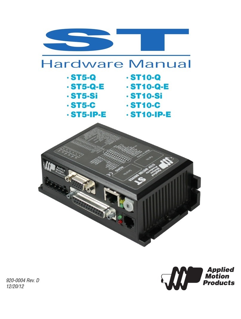
Ⅲ. Backpanel diagram and signal descriptions
1. CP,CW, OPTO for steppermotordrive signal;
CP: pulse signal
CW: direction signal
0PT0: Publicmale end beforethetwosignals
2. RUN: Start runningtheprogram,Thesamefunction as
Run”of the operationpanel;
3. STOP: Pauseprogramis run automatically,Thesame
functionas Pause”of theoperation panel,Afterstarting
again, theprogramcontinuestorun;
4. A: Aoperation
B: Boperation
Aoperation”and Boperation”this isamajor feature ofthe controller:
For steppermotors,wegenerally quantitativepositioning control,such ascontrollingthe
displacementof themotor mustberunning ataconstantspeed ,Inthis wayitis easytosolve,
justputthe amountandspeedof displacementofthe programming canbe.
But therearequitealot of control isnotpositioningin advance, such ascontrollingthe
steppermotor inonedirectionfromthe starting pointtostartrunninguntilhe hit aswitchafter
strokestop,thenreversedirectionbacktothestartingpoint. Anotherexamplerequiresthe
steppermotor runningbackandforth betweenthetwolimit switchseveraltimes,andso on. In
theseoperations,wedo not knowin advancethespecificvalueof thesteppermotor
displacement,andhow theyshould beprogrammedit?Thecontrolleruses: tointerruptthe
operation,which wecall "AOperation" and "B operation”,for example,"Aoperations",workers
workflowis:whenthe programisrunning. If"Aoperation" signalinput,motor deceleratesto
stop,Programinterruption,the controllerremembersinterruptedcoordinate values, theprogram
jumpstothe "Aoperation" entry address specifiedprograms runtheprogram;
5. IN1 and IN2 Switchingsignalinput terminal
6.OUT1,OUT2 and OUT3 Switching signaloutputterminal,
7.COM+, COM- :thepowersupply of externalinput and outputdevices,thispowersupply is
DC24V, COM+ is thepositive terminalof thepowersupply,COM- negative side;
8. +24V: The positivepowersupply,GND: Negative powersupply;
Thesignal RUN,STOP,A , B , IN1, IN2 calledtheinput signal,theyhavethesameinput interface
circuit. OUT1, OUT2,0UT3 calledtheoutputsignal. Theyhavethesameoutput interfacecircuit.
Both inputand outputopticalisolation circuittoensurethattheinternaland externalcontrollers
do not interferewitheach other;
Thestateoftheinput signaland outputsignal,corresponding indicator on the panel. For input,
inputlow(switchisclosed) Indicator light;For outputsignal,theoutput 0islow,thelightisoff,
theopposite willlight.
Figure II:Back paneldiagram


